
mud pump working principle made in china

What is a mud pump? A mud pump refers to a machine that transports mud or water and other flushing fluid into the borehole during drilling. Types of mud pumps are an important part of drilling equipment. In the commonly used positive circulation drilling, it is to send the surface flushing medium—clear water, mud, or polymer rinsing liquid to the bottom end of the drill bit through a high-pressure hose, faucet, and drill rod center hole under a certain pressure. Cool the drill bit, remove the cut debris and transport it to the surface.
The commonly used mud pump is a piston-type or a plunger type, and the crankshaft of the pump is driven by the power machine, and the crankshaft passes the crosshead to drive the piston or the plunger to reciprocate in the pump cylinder. Under the alternating action of the suction and discharge valves, the purpose of pumping and circulating the flushing liquid is achieved.
During operation, the power machine drives the main shaft and the crank that is fixed thereon by a transmission component such as a belt, a transmission shaft, and a gear. When the crank rotates counterclockwise from the horizontal position from left to right, the piston moves to the power end, the pressure in the liquid cylinder gradually decreases and a vacuum is formed, and the liquid in the suction pool is under the action of the liquid surface pressure, and the suction valve is opened to enter the liquid cylinder. Until the piston moves to the right stop. This working process is called the suction process of the pump.
After the crank completes the above suction process, it continues to rotate counterclockwise. At this time, the piston starts to move toward the hydraulic end (left side in the figure), and the liquid in the cylinder is squeezed. The pressure rises, the suction valve closes, and the discharge valve is closed. Top open, liquid enters the discharge pipe until the piston moves to the left stop. This process is called the pump discharge process. As the power machine continues to operate, the reciprocating pump continuously repeats the process of inhaling and discharging, and the liquid in the suction pool is continuously sent to the bottom of the well through the discharge pipe.
Mud pump is mainly used for geological drilling, geological engineering construction and foundation treatment of low and medium pressure grouting pump, etc. Mud pump is a machine that sends mud or water to the borehole during the drilling process. Mud pump is an important part of drilling equipment. All major businesses have mud pump parts for sale.
The main function of mud pump is to inject mud into the well along with the bit during the drilling process. It plays the role of cooling the drill bit, cleaning the drilling tool, fixing the well wall, driving drilling, and bringing the cuttings back to the surface after drilling.
In the commonly used positive circulation drilling, the mud pump sends the surface flushing medium-- clean water, mud or polymer flushing fluid to the end of the drill bit through the high pressure hose faucet and the center hole of the drill string under a certain pressure. Therefore, the purpose of cooling the drill bit and removing and conveying the cuttings to the surface is achieved.
Petroleum drilling mud pump is a kind of volumetric mud pump. Its basic working principle is that the volume of the sealed working chamber (mud pump cylinder liner) is periodically changed to convert the original mechanical energy into the pressure energy of the liquid to complete the operation.
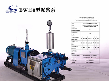
The specific process relies on the reciprocating motion of the mud pump piston in the cylinder liner to make the volume of the working chamber in the cylinder liner change periodically. The mud pump cylinder liner is isolated from the outside world by means of a sealing device such as a seal ring, and communicates or closes with the pipeline through the pump valve (suction valve or discharge valve), which shows the importance of the mud pump cylinder liner. The three-cylinder mud pumps currently on the market are equipped with three cylinder sleeves.

A mud pump (sometimes referred to as a mud drilling pump or drilling mud pump), is a reciprocating piston/plunger pump designed to circulate drilling fluid under high pressure (up to 7,500 psi or 52,000 kPa) down the drill string and back up the annulus. A mud pump is an important part of the equipment used for oil well drilling and manufactured according to API specification 7K.
The advantages of the drilling mud pump include the ability to move high-solids-content fluids laden with abrasives, the ability to pump large particles, ease of operation and maintenance, reliability, and the ability to operate over a wide range of pressures and flow rates by changing the diameter of pump liners and pistons.
As an important equipment for oilfield drilling operation, a drilling mud pump delivers circulating high-pressure drilling fluid or drilling mud to the bottom of the oil well, flushes the bottom of the well, breaks the rock, cools, lubricates and clean the drill bit, and carries the cuttings back to the ground.
The drilling mud is also used to suspend and carry out drill cuttings from the drill bits as it is brought in and out of the hole. This ensures that the drill bit does not clog and overheat, and makes the entire drilling operation smooth and safe.
Rotational power is supplied to the mud pump through an external power source like a diesel engine or electric motor. The power end of the mud pump converts the rotational energy through a crankshaft to a reciprocating motion of pistons.
The pistons move back and forth in mud pump liners, exerting a force on the cylinder chamber. During the retraction of the piston, valves open to allow the fluid to be drawn into the cylinder. Once the piston has fully retracted, it is pushed back into the cylinder.

Mud hog pump is used to circulate oil drilling mud on a drilling rig at high pressure. Drilling fluid or oil drilling mud is circulated down through the drill string, to help cool, lubricate and clean the drill head, and back through the annulus at high pressures. The drilling mud is also used to suspend and carry out drill cuttings from the drill head as it is brought in and out of the hole.
We can provide more types of mud pumps than other oil well drilling equipment suppliers, and the classification methods are different. There are roughly the following types:
According to the number of times a piston reciprocates in a cylinder to inhale or discharge liquid once, it is divided into sing-acting pump and double-acting pump.
According to different driven method, it is divided into diesel mud pump and electric mud pump.It depends on fuel or energy which is available on around area of drilling rigs.

Find W series mud pump from pressure grouting pump manufacturer - Saigao gruop in China. The W series mud pump can be widely used in all kinds of works in oil field, which is su...

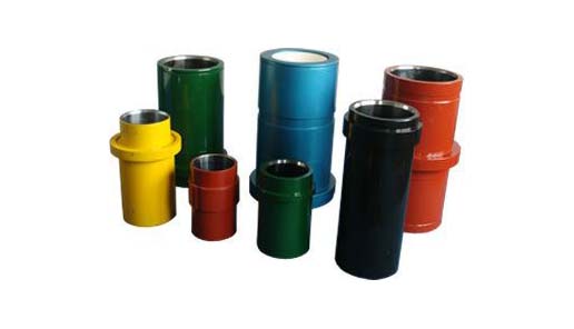
A Mud Pump may have many changeable parts, such as liner, piston, extension rod, pulsation dampener, valve, clamp, etc. Lake Petro could provide 100% interchangeable parts of many common brands of pump. We offer Liners with Ceramic (Zirconia and Aluminium oxide) and Steel (Metal and Bi-metal) materials. Piston assembly is the important spare parts and expendable parts of oil drilling mud pumps. Mud pump valve assy include valve body, valve seat, valve insert (valve rubber ). Pulsation Dampener is usually installed on the discharge line to reduce the fluctuation of pressure and displacement of the drilling mud pump. Fluid End Module is an important component of the hydraulic pump end of the mud pump.

Slurry pumps are mainly used in industrials of mining, metallurgy, dredge, power, coal and other solid slurry transport. Mud pumps are mainly used for drilling, pharmaceutical, brewing, paper, and other industries, which used to transport suspension.
The slurry pump is mainly used in the mining industry, its wear resistance is strong. So It conveys slurry that containing slag, but it can conveys mud. The mud pump is usually made of cast iron, the wear resistance of the pump is low. So the mud pumps often used for conveying mud or slurry containing suspended particles. When the slurry pump working, pump parts are easy to be impacted, wear, and corrosion, etc. Therefore, the liner of the slurry pump uses wear-resistant material, such as high chromium alloy, rubber. The wear-resistant materials can effectively reduce the wear parts of the pump. So most of the slurry pump is a wear-resistant slurry pump in the current market.
The mud pump is the motor driving the piston move through the link mechanism. Then causes the change of the volume of the sealed chamber of the mud pump. and the pressure difference between inside and outside of the pump change. Finally, the process of absorbing water and draining water is complete. When slurry pump working, which is the motor drives the impeller rotation. That is the impeller on the slurry work which increases the kinetic energy of the slurry. At the same time, the slurry flows to the edge of the impeller due to inertia and is discharged from the discharge pipe at a high speed.
The Mud pumps need to be equipped with auxiliary equipment, but slurry pumps not. They often need to use with high-pressure water pump when mud pump working. The high-pressure pump sent the water that larger than the mud pump pressure to the leakproof packing. Then protect the packing. Otherwise, it is easy to make the seal part wear. But the wear-resistant slurry pumps can complete the transportation work independently, which not need to equip other auxiliary equipment.
In a word, the wear-resistant properties of the slurry pumps are stronger, and the ability to convey particles is also stronger. Generally, the capacity of the slurry pump is larger than the mud pump, which is mainly used for coal and metal ore washing. The mud pumps are more suitable for abrasive slurry is not very strong.
1. The two types of pumps are all centrifugal pumps in the working principle. They are machines that increase the energy of solid and liquid mixtures by means of centrifugal force (the rotation of the impeller of the pump). A device that converts electrical energy into kinetic and potential energy of a medium.
The piston is one of the parts that most easily become worn out and experience failure in mud pumps for well drilling. By imitating the body surface morphology of the dung beetle, this paper proposed a new type (BW-160) of mud pump piston that had a dimpled shape in the regular layout on the piston leather cup surface and carried out a performance test on the self-built test rig. Firstly, the influence of different dimple diameters on the service life of the piston was analyzed. Secondly, the analysis of the influence of the dimple central included angle on the service life of the piston under the same dimple area density was obtained. Thirdly, the wear of the new type of piston under the same wear time was analyzed. The experimental results indicated that the service life of the piston with dimples on the surface was longer than that of L-Standard pistons, and the maximum increase in the value of service life was 92.06%. Finally, the Workbench module of the software ANSYS was used to discuss the wear-resisting mechanism of the new type of piston.
The mud pump is the “heart” of the drilling system [1]. It has been found that about 80% of mud pump failures are caused by piston wear. Wear is the primary cause of mud pump piston failure, and improving the wear-resisting performance of the piston-cylinder friction pair has become the key factor to improve the service life of piston.
Most of the researchers mainly improve the service life of piston through structural design, shape selection, and material usage [1, 2]. However, the structure of mud pump piston has been essentially fixed. The service life of piston is improved by increasing piston parts and changing the structures of the pistons. However, the methods have many disadvantages, for example, complicating the entire structure, making piston installation and change difficult, increasing production and processing costs, and so on. All piston leather cup lips use rubber materials, and the material of the root part of the piston leather cup is nylon or fabric; many factors restrict piston service life by changing piston materials [3]. Improving the component wear resistance through surface texturing has been extensively applied in engineering. Under multiple lubricating conditions, Etsion has studied the wear performance of the laser surface texturing of end face seal and reciprocating automotive components [4–6]. Ren et al. have researched the surface functional structure from the biomimetic perspective for many years and pointed out that a nonsmooth surface structure could improve the wear resistance property of a friction pair [7, 8]. Our group has investigated the service life and wear resistance of the striped mud pump piston, and the optimal structure parameters of the bionic strip piston have improved piston service life by 81.5% [9]. Wu et al. have exploited an internal combustion engine piston skirt with a dimpled surface, and the bionic piston has showed a 90% decrease in the average wear mass loss in contrast with the standard piston [10]. Gao et al. have developed bionic drills using bionic nonsmooth theory. Compared with the ordinary drills, the bionic drills have showed a 44% increase in drilling rate and a 74% improvement in service life [11]. The present researches indicate that microstructures, like superficial dimples and stripes, contribute to constituting dynamic pressure to improve the surface load-carrying capacity and the wear resistance of the friction pair [12–21].
In nature, insects have developed the excellent wear-resistant property in the span of billions of years. For instance, the partial body surface of the dung beetle shows an irregularly dimpled textured surface with the excellent wear-resistant property that is conducive to its living environment [7, 8, 22]. The dung beetle, which is constantly active in the soil, shows a body surface dimple structure that offers superior drag reduction. These dimples effectively reduce the contact area between the body surface and the soil. Moreover, the friction force is reduced. Therefore, the dung beetle with the nonsmooth structure provides the inspiration to design the bionic mud pump piston. This paper proposed a new type of piston with dimpled morphology on its surface and conducted a comparative and experimental study of different surface dimpled shapes, thus opening up a new potential to improve the service life of the mud pump piston.
A closed-loop circulatory system was used in the test rig, which was built according to the national standard with specific test requirements. The test rig consisted of triplex single-acting mud pump, mud tank, in-and-out pipeline, reducer valve, flow meter, pressure gauge, and its principle, as shown in Figure 1. Both the pressure and working stroke of the BW-160 mud pump are smaller than those of the large-scale mud pump, but their operating principles, structures, and working processes are identical. Therefore, the test selected a relatively small BW-160 triplex single-acting mud pump piston as a research object, and the test results and conclusion were applicable to large-scale mud pump pistons. The cylinder diameter, working stroke, reciprocating motion velocity of piston, maximum flow quantity, and working pressure of the BW-160 triplex single-acting mud pump were 70 mm, 70 mm, 130 times/min, 160 L/min, and 0.8–1.2 MPa, respectively.
The mud pump used in the test consisted of water, bentonite (meeting the API standard), and quartz sand with a diameter of 0.3–0.5 mm according to actual working conditions. The specific gravity of the prepared mud was 1.306, and its sediment concentration was 2.13%. Whether mud leakage existed at the venthole in the tail of the cylinder liner of the mud pump was taken as the standard of piston failure. Observation was made every other half an hour during the test process. It was judged that the piston in the cylinder failed when mud leaked continuously; its service life was recorded, and then it was replaced with the new test piston and cylinder liner. The BW-160 mud pump is a triplex single-acting mud pump. The wear test of three pistons could be simultaneously conducted.
The mud pump piston used in the test consisted of a steel core, leather cup, pressing plate, and clamp spring. The leather cup consisted of the lip part of polyurethane rubber and the root part of nylon; the outer diameter on the front end of the piston was 73 mm, and the outer diameter of the piston tail was 70 mm, as shown in Figure 2. We proceeded in two parts during the design of the dimpled layout pattern because the piston leather cup consisted of two parts whose materials were different. The dimples at the lip part of the leather cup adopted an isosceles triangle layout pattern, and the dimples at the root part were arranged at the central part of its axial length, as shown in Figure 3(a). Dimple diameter (D, D′), distance (L), depth (h), and central included angle (α) are shown in Figure 3. The dimples on the piston surface were processed by the CNC machining center. Since then, the residual debris inside the dimples was cleaned.
Table 1 shows that average service lives of L-Standard, L-D1, L-D2, and L-D3 were 54.67 h, 57.17 h, 76.83 h, and 87.83 h, respectively. Therefore, the mud pump pistons with dimples provide longer service life than the L-Standard piston. As the dimple diameter increases, the piston service life was improved, and the largest percentage increase of the service life was 60.65%. The service life of the L-D4 piston was about 81.17 h, which increased by 7.94% compared with that of the L-D2 piston, indicating that the piston with dimples at the leather cup root could improve piston service life.
Figure 4 illustrates the surface wear patterns of pistons with different dimple diameters in the service life test. Figures 4(a) and 4(a′) show wear patterns on the surface of the L-Standard piston. This figure shows that intensive scratches existed in parallel arrangement on the piston leather cup surface, enabling high-pressure mud to move along the scratches from one end of the piston to the other easily, which accelerated the abrasive wear failure with the abrasive particles of the piston. Figures 4(b), 4(b′), 4(c), 4(c′), 4(d), and 4(d′) show the wear patterns of the leather cup surfaces of L-D1, L-D2, and L-D3 pistons, respectively. Figures 4(b), 4(b′), 4(c), 4(c′), 4(d), and 4(d′) show that the scratches on the leather cup surface became shallower and sparser and the surface wear patterns improved more obviously as the dimple diameter increased. If the piston leather cup surface strength was not affected to an extent as the dimple diameter increased, the reduced wear zone near the dimple would become greater and greater, indicating that the existence of dimples changed the lubricating status of the leather cup surface, their influence on nearby dimpled parts was more obvious, and they played active roles in improving the service life of the piston.
Figure 5 displays the wear patterns of the leather cup root parts of the L-D4 and L-D2 test pistons. The wear patterns of the nylon root parts of the L-D4 pistons are fewer than those of the L-D2 pistons, as shown in Figure 5. When the leather cup squeezed out high-pressure mud as driven by the piston steel core, it experienced radial squeezing while experiencing axial wear. Therefore, the area with the most serious wear was the piston leather cup root part, and the friction force at the leather cup root was much greater than that at the other areas. The rapid wear at the root decreased the piston load-carrying capacity and then affected the service life of piston. The dimples at the piston leather cup root could reduce the wear of the piston leather cup root and improve the service life of piston.
Figure 6 shows the surface wear patterns of the L-S1 and L-S2 test pistons. In Figures 6(a) and 6(a′), the scratches on the piston leather cup surface became sparse and shallow in the dimpled area. Figures 6(b) and 6(b′) show that the wear was slight in the area close to the dimples. The farther the scratches were from the dimpled area, the denser and deeper the scratches would be. The L-S1 piston had a small dimple central included angle, which was arranged more closely on the piston surface. The lubricating effects of oil storage in each row of dimples were overlaid very well, which was equivalent to amplifying the effect of each row of dimples in Figure 6(b), making the wear on the whole piston leather cup surface slight, preventing the entry of high-pressure mud into the frictional interface, and lengthening the service life of piston.
During the operation of the mud pump piston, the outside surface of the piston leather cup comes in contact with the inner wall of the cylinder liner and simultaneously moves to push the mud. The lip part of the piston leather cup mainly participated in the piston wear and exerted a sealing effect, while the piston root part mainly exerted centralizing and transitional effects. In the mud discharge stroke, the lip part of the piston experienced a “centripetal effect,” and a gap was generated between the lip part and the cylinder liner. The greater the contact pressure between the lip part and cylinder liner of the piston was, the smaller the gap was, and the entry of high-pressure mud into the contact surface between the piston and cylinder liner was more difficult. The piston root easily experienced squeezing under high pressure, and the smaller the equivalent stress caused by the piston root was, the more difficult the squeezing to occur. Hence, the contact pressure at the lip part of the piston and the equivalent stress at the root were analyzed, and they would provide a theoretical basis for the piston wear-resisting mechanism. The ANSYS Workbench module was used to perform a comparative analysis between the contact pressure at the lip part and the equivalent stress at the root of the three kinds of pistons (i.e., L-Standard piston, L-S1 piston, and L-D1 piston). The service life of the L-S1 piston exhibited the best improvement effect, whereas that of the L-D1 piston demonstrated the worst improvement effect. The piston adopted a 1 mm hexahedral grid, and the grid nodes and elements are as shown in Table 4.
The lubricating oil on the mud pump piston surface could reduce the wear of piston and cylinder liner and improve the service life of pistons with the reciprocating movement. The lubricating oil would eventually run off and lose lubricating effect, which would result in piston wear. The finite element fluid dynamics software CFX was used to establish the fluid domain model of the dimpled and L-Standard pistons and analyze the lubricating state on the piston surface. The piston surface streamlines are shown in Figure 10. This figure shows that the lubricating fluid did not experience truncation or backflow phenomenon when passing the surface of the L-Standard piston. When the lubricating fluid flowed through the surface of the dimpled piston, it presented a noncontinuous process. Its flow velocity at the dimpled structure slowed down obviously because it was blocked by the dimpled structure.
When the piston moved in the cylinder liner, a small quantity of solid particles in mud entered gap of piston and cylinder liner and participated in abrasion. The dimpled structure on the piston surface could store some abrasive particles (as shown in Figure 6(a′)) during the piston wear process to prevent these particles from scratching the piston and cylinder liner and generating gullies, thus avoiding secondary damage to the piston and cylinder liner and improving the piston service life.
This paper presented a dimpled-shape mud pump piston; that is, the piston leather cup surface had a dimpled array morphology in regular arrangement. The experimental results can provide the basic data for design engineering of the mud pump piston with a long service life. The comparative analyses of service life and wear patterns for dimpled mud pump pistons and L-Standard pistons were conducted. The main results and conclusions were summarized as follows:(1)The service life of the mud pump piston with dimpled morphology on the surface improved in comparison with that of the L-Standard piston, and the service life increase percentages were from 4.57% to 92.06%.(2)The piston service life would increase with the dimple diameter under the same dimpled arrangement pattern, and the maximum increase in the value of service life was 60.65%.(3)The service life of the piston with dimples increased by 7.94% in comparison with that with none.(4)Under the same dimpled arrangement patterns and area densities, the tighter and closer the dimples were arranged on the piston surface, the longer the service life of piston was, and the maximum increase in the value of service life was 92.06%.(5)Under the same wear time, the wear of the dimpled piston slightly decreased in comparison with that of the L-Standard piston, and the minimum value of wear mass percentage was 3.83%.(6)The dimpled shape could not only change the stress state of the piston structure, improve piston wear resistance, and reduce root squeezing, but also increase oil storage space, improve lubricating conditions, and enable the accommodation of some abrasive particles. Furthermore, the dimpled shape was the key factor for the service life improvement of the mud pump piston.
The drilling industry has roots dating back to the Han Dynasty in China. Improvements in rig power and equipment design have allowed for many advances in the way crude oil and natural gas are extracted from the ground. Diesel/electric oil drilling rigs can now drill wells more than 4 miles in depth. Drilling fluid, also called drilling mud, is used to help transfer the dirt or drill cuttings from the action of the drilling bit back to the surface for disposal. Drill cuttings can vary in shape and size depending on the formation or design of the drill bit used in the process.
Watch the video below to see how the EDDY Pump outperforms traditional pumps when it comes to high solids and high viscosity materials commonly found on oil rigs.
The fluid is charged into high-pressure mud pumps which pump the drilling mud down the drill string and out through the bit nozzles cleaning the hole and lubricating the drill bit so the bit can cut efficiently through the formation. The bit is cooled by the fluid and moves up the space between the pipe and the hole which is called the annulus. The fluid imparts a thin, tough layer on the inside of the hole to protect against fluid loss which can cause differential sticking.
The fluid rises through the blowout preventers and down the flowline to the shale shakers. Shale shakers are equipped with fine screens that separate drill cutting particles as fine as 50-74 microns. Table salt is around 100 microns, so these are fine cuttings that are deposited into the half-round or cuttings catch tank. The drilling fluid is further cleaned with the hydro-cyclones and centrifuges and is pumped back to the mixing area of the mud tanks where the process repeats.
The drill cuttings contain a layer of drilling fluid on the surface of the cuttings. As the size of the drill cuttings gets smaller the surface area expands exponentially which can cause rheological property problems with the fluid. The fluid will dehydrate and may become too thick or viscous to pump so solids control and dilution are important to the entire drilling process.
One of the most expensive and troubling issues with drilling operations is the handling, processing, and circulation of drilling mud along with disposing of the unwanted drill cuttings. The drilling cuttings deposited in the half round tank and are typically removed with an excavator that must move the contents of the waste bin or roll-off box. The excavators are usually rented for this duty and the equipment charges can range from $200-300/day. Add in the cost for the day and night manpower and the real cost for a single excavator can be as much as $1800/day.
Using the excavator method explained above, the unloading of 50 barrels of drill cuttings from the half round can take as long as two hours. This task is mostly performed by the solids control technicians. The prime duty for the solids control technicians is to maintain the solids control equipment in good working order. This involves maintenance for the equipment, screen monitoring and changing, centrifuge adjustments, and retort testing to prepare a daily operational summary of the solids control program.
Offshore drilling rigs follow a similar process in which the mud is loaded into empty drums and held on the oil platform. When a certain number of filled drums is met, the drums are then loaded onto barges or vessels which take the drilling mud to the shore to unload and dispose of.
Oil field drilling operations produce a tremendous volume of drill cuttings that need both removal and management. In most cases, the site managers also need to separate the cuttings from the drilling fluids so they can reuse the fluids. Storing the cuttings provides a free source of stable fill material for finished wells, while other companies choose to send them off to specialty landfills. Regardless of the final destination or use for the cuttings, drilling and dredging operations must have the right high solids slurry pumps to move them for transport, storage, or on-site processing. Exploring the differences in the various drilling fluids, cutting complications, and processing options will reveal why the EDDY Pump is the best fit for the job.
The Eddy Pump is designed to move slurry with solid content as high as 70-80 % depending on the material. This is an ideal application for pumping drill cuttings. Drill cuttings from the primary shakers are typically 50% solids and 50% liquids. The Eddy Pump moves these fluids efficiently and because of the large volute chamber and the design of the geometric rotor, there is very little wear on the pump, ensuring long life and greatly reduced maintenance cost for the lifetime of the pump.
plumbed to sweep the bottom of the collection tank and the pump is recessed into a sump allowing for a relatively clean tank when the solids are removed. The Eddy Pump is sized to load a roll-off box in 10-12 minutes. The benefit is cuttings handling is quicker, easier, safer, and allows for pre-planning loading where the labor of the solids control technician is not monopolized by loading cuttings. Here, in the below image, we’re loading 4 waste roll-off bins which will allow the safe removal of cuttings without fear of the half-round catch tank running over.
Mud cleaning systems such as mud shaker pumps and bentonite slurry pumps move the material over screens and through dryers and centrifuges to retrieve even the finest bits of stone and silt. However, the pump operators must still get the raw slurry to the drill cuttings treatment area with a power main pump. Slurry pumps designed around the power of an Eddy current offer the best performance for transferring cuttings throughout a treatment system.
Options vary depending on whether the company plans to handle drill cuttings treatment on-site or transport the materials to a remote landfill or processing facility. If the plan is to deposit the cuttings in a landfill or a long-term storage container, it’s best to invest in a pump capable of depositing the material directly into transport vehicles. Most dredging operations rely on multiple expensive vacuum trucks, secondary pumps, and extra pieces of equipment.
Using an EDDY Pump will allow a project to eliminate the need for excavators/operators to load drill cuttings, substantially lowering both labor and heavy equipment costs. The EDDY Pump also allows a company to eliminate vacuum trucks once used for cleaning the mud system for displacing fluids. Since the pump transfers muds of all types at constant pressure and velocity throughout a system of practically any size, there’s little need for extra equipment for manual transfer or clean up on the dredge site.
The EDDY Pump can fill up a truck in only 10 minutes (compared to an hour) by using a mechanical means such as an excavator. For this reason, most companies can afford one piece of equipment that can replace half a dozen other units.
This application for the Eddy Pump has the potential to revolutionize the drilling industry. Moving the excavator out of the “back yard” (the area behind the rig from the living quarters) will make cuttings handling a breeze. Trucking can be easier scheduled during daylight hours saving on overtime and incidences of fatigued driving. Rig-site forklifts can move the roll-off boxes out of the staging area and into the pump loading area. The operator can save money on excavators rental, damages, and keep the technician operating the solids control equipment.
The EDDY Pump is ideal for drilling mud pump applications and can be connected directly onto the drilling rigs to pump the drilling mud at distances over a mile for disposal. This eliminates the need for costly vacuum trucks and also the manpower needed to mechanically move the drilling mud. The reasons why the EDDY Pump is capable of moving the drilling mud is due to the hydrodynamic principle that the pump creates, which is similar to the EDDY current of a tornado. This tornado motion allows for the higher viscosity and specific gravity pumping ability. This along with the large tolerance between the volute and the rotor allows for large objects like rock cuttings to pass through the pump without obstruction. The large tolerance of the EDDY Pump also enables the pump to last many times longer than centrifugal pumps without the need for extended downtime or replacement parts. The EDDY Pump is the lowest total life cycle pump on the market.
Drilling consumables such as mud pump systems and their components can drastically increase your uptime while reducing costs and health/safety/environmental (HSE) risks. To support your drilling needs, Forum’s patented P-Quip® mud pump system offers a single-source solution that integrates high-quality fluid end components for maximum longevity and performance.
With more than 20 years of successful operation in severe environments, P-Quip offers a proven track record for the lowest cost of ownership in the industry. As part of our commitment to quality, our mud pump parts use patented Banded Bore™ technology that significantly reduces stress concentrations and leads to longer module life.
One of Forum’s most committed core values is that “no one gets hurt,” and the P-Quip system is designed to support that principle. Streamlined and easy to use, it reduces or eliminates the need for manual force during maintenance, shrinking the time needed to replace high-use components and minimizing safety risks.

Piston high-density pump is one of capital equipment of core drilling engineering, and its effect is to provide the cooling drill bit of highly pressurised liquid (water), in the Hydraulic and Hydro-Power Engineering prospecting, is also the capital equipment of water pressure test in borehole usually.Piston high-density pump mainly is comprised of transmission system (gear), connecting rod, pump head (inlet valve, drain valve), frame.The piston of piston high-density pump is realized the linear reciprocating motion in pump chamber by transmission system (gear) and connecting rod, thereby changes volume realization water suction and the draining of pump chamber.The fluid pressure of piston high-density pump output has pulse characteristic.The pulse of fluid pressure affects the working life of pipeline, the correct collection of impact to test data in water conservancy and hydropower drilling project water pressure test in borehole.As shown in Figure 1, in order to reduce the pulse of pressure, prior art is to install an air chamber as stable-pressure device 3 on the outlet pipe 4 of piston high-density pump 2, the pressurized vessel that described stable-pressure device 3 is a cavity, be provided with through hole 5 in the bottom of pressurized vessel, the through hole 5 of pressurized vessel is connected on outlet pipe 4 by three-way pipe.1 is intake pipe.
Its principle of stabilized voltage is that the compression property of application gas is subdued crest and the trough with compensatory pressure pulsation liquid, realizes the stable of pressure.When the water pressure of discharging when pump is large (crest), the high pressure water in outlet pipe 4 makes the air compressing of air chamber, and air pressure increases, and water pressure reduces; When the water pressure hour (trough) that pump is discharged, the air spreading of air chamber, air pressure reduces, and water pressure increases.Thereby reduce the water pressure fluctuation in outlet pipe 4.
But, the stable-pressure device of prior art (pressurized vessel), the air in pressurized vessel with the liquid in outlet pipe without separating, pump is in operation, liquid in outlet pipe is often invaded in pressurized vessel, in outlet pipe 4, causes voltage regulation result poor part Bas Discharged in the air chamber pressurized vessel.

BW Piston pump mud pump for drilling rig for grouting cement With factory price on Sale is mainly used to grout cement, slurry, paste and mud into holes to support and anchor in geology, mining, construction, metallurgy, railway, chemical engineering, water conservancy, petroleum exploration, etc. It can also be used to inject fluids while drilling holes to lower the temperature and clean the broken stone and soil.

The utility model discloses a pressure compensation device for oil hydraulic ceramic plunger mud pumps, and relates to the field of pressurizing devices for conveying slurry in an oil hydraulic drive mode. An oil pump (1) is connected with a variable piston (2), a pressure control (PC) valve (3), a remote pressure regulating valve (4), a one-way valve (5) and a fluid flow valve (11), wherein the variable piston (2) is connected with the PC valve (3), the PC valve (3) is connected with the remote pressure regulating valve (4), the one-way valve (5) is connected with a rotating valve (7) and an oil inlet end of a hydraulic directional valve (6), the oil inlet end of the hydraulic directional valve (6) is connected with an oil cylinder (8), and an oil outlet end of the hydraulic directional valve (6) is connected with another oil cylinder (8). Each oil cylinder (8) is connected with one ceramic plunger (9), and the two ceramic plungers (9) are respectively arranged inside two mud pump bodies (10). The pressure compensation device for the oil hydraulic ceramic plunger mud pumps enables the output power of a YB pump to be equal to the output power of the oil pump, and therefore power consumption is lowered to a large extent, efficiency is improved, and the service life of the YB plunger pump is prolonged.
The utility model relates to oil pressure actuated and carries slurry pressurized equipment field, relates in particular to oil pressure ceramic plunger slurry pump pressure compensator.
At present, the YB plunger pump is divided into quantitatively and two kinds of forms of variable, metering pump is driven by the quantitative oil pump fuel feeding, variable displacement pump is driven by two quantitative oil pump classification fuel feeding, no matter but which kind of adopts for oil form, all be difficult to adapt to the variation of bearing power, now take pressure filter as load as example, pressure filter is a kind of dewatering by extruding equipment, the general YB plunger pump of using is for the slurry pressurization, and slurry flow is larger when initial, and the YB plunger pump is in normal working, but because the saturated accumulation with expecting matter of the volume of pressure filter, the delivery side of pump increased pressure, required flow also reduces gradually simultaneously, and the input power of YB plunger pump does not change, so just cause very large power loss, and most of energy that loses all will be discharged by the fluid valve from hydraulic system, thereby can cause system"s heating, and oil temperature raises, not only can affect the YB plunger pump life-span, also can quit work when serious.
The purpose of this utility model provides oil pressure ceramic plunger slurry pump pressure compensator, and it can make YB delivery side of pump power equal the output power of oil pump, has reduced significantly energy consumption, has improved efficient, has prolonged the working life of YB plunger pump.
In order to solve the existing problem of background technique, the utility model is by the following technical solutions: it is comprised of oil pump 1, variable piston 2, PC valve 3, remote pressure regulating valve 4, one-way valve 5, hydraulicchange-over valve 6, rotary valve 7, oil cylinder 8, ceramic plunger 9, the mud pump housing 10, fluid valve 11; Oil pump 1 is connected with fluid valve with variable piston 2, PC valve 3, remote pressure regulating valve 4, one-way valve 5 respectively and is connected, variable piston 2 is connected with PC valve 3, PC valve 3 is connected with remote pressure regulating valve 4, one-way valve 5 is connected with the oil inlet end that rotary valve 7 is connected with hydraulicchange-over valve respectively, and the oil inlet end of hydraulicchange-over valve 6 and oil outlet end connect respectively a group oil cylinder 8, two oil cylinders 8 are connected with two ceramic plungers 9 respectively, and two ceramic plungers 9 are separately positioned in two mud pump housings 10.
Working principle of the present utility model: take supporting pressure filter as example, oil pump 1 output peak rate of flow, when the required flow of pressure filter reduces, oil pump outlet pressure P
PEffect under, PC valve 3 moves to left, the left chamber of pressure oil entering variable piston is reduced the oil pump output flow, straight ending when zero worked as P
SThe time, remote pressure regulating valve 4 is closed, under spring-force driven dual, PC valve 3 cores move to right, and oil is rushed down by PC valve 3 in the left chamber of variable oil cylinder, and the oil pump output flow increases, this flow matches type oil hydraulic circuit, can realize the stepless variable of YB ceramic plunger slurry pump, it can adapt to the linear change of load flow, and its bearing power and oil pump output power are complementary.
The utility model can make YB delivery side of pump power equal the output power of oil pump, has reduced significantly energy consumption, has improved efficient, has prolonged the working life of YB plunger pump.
With reference to Fig. 1, this embodiment by the following technical solutions: it is comprised of oil pump 1, variable piston 2, PC valve 3, remote pressure regulating valve 4, one-way valve 5, hydraulicchange-over valve 6, rotary valve 7, oil cylinder 8, ceramic plunger 9, the mud pump housing 10, fluid valve 11; Oil pump 1 is connected with fluid valve with variable piston 2, PC valve 3, remote pressure regulating valve 4, one-way valve 5 respectively and is connected, variable piston 2 is connected with PC valve 3, PC valve 3 is connected with remote pressure regulating valve 4, one-way valve 5 is connected with the oil inlet end that rotary valve 7 is connected with hydraulicchange-over valve respectively, and the oil inlet end of hydraulicchange-over valve 6 and oil outlet end connect respectively a group oil cylinder 8, two oil cylinders 8 are connected with two ceramic plungers 9 respectively, and two ceramic plungers 9 are separately positioned in two mud pump housings 10.
The working principle of this embodiment: take supporting pressure filter as example, oil pump 1 output peak rate of flow, when the required flow of pressure filter reduces, oil pump outlet pressure P
PEffect under, PC valve 3 moves to left, the left chamber of pressure oil entering variable piston is reduced the oil pump output flow, straight ending when zero worked as P
SThe time, remote pressure regulating valve 4 is closed, under spring-force driven dual, PC valve 3 cores move to right, and oil is rushed down by PC valve 3 in the left chamber of variable oil cylinder, and the oil pump output flow increases, this flow matches type oil hydraulic circuit, can realize the stepless variable of YB ceramic plunger slurry pump, it can adapt to the linear change of load flow, and its bearing power and oil pump output power are complementary.
This embodiment can make YB delivery side of pump power equal the output power of oil pump, has reduced significantly energy consumption, has improved efficient, has prolonged the working life of YB plunger pump.
1. oil pressure ceramic plunger slurry pump pressure compensator is characterized in that it is comprised of oil pump (1), variable piston (2), PC valve (3), remote pressure regulating valve (4), one-way valve (5), hydraulicchange-over valve (6), rotary valve (7), oil cylinder (8), ceramic plunger (9), the mud pump housing (10), fluid valve (11); Oil pump (1) respectively with variable piston (2), PC valve (3), remote pressure regulating valve (4), one-way valve (5) is connected 11 with fluid valve) connect, variable piston (2) is connected with PC valve (3), PC valve (3) is connected with remote pressure regulating valve (4), one-way valve (5) is connected 6 with rotary valve (7) with hydraulicchange-over valve respectively) oil inlet end be connected, and the oil inlet end of hydraulicchange-over valve (6) and oil outlet end connect respectively a group oil cylinder (8), two oil cylinders (8) are connected with two ceramic plungers (9) respectively, and two ceramic plungers (9) are separately positioned in two mud pump housings (10).


 8613371530291