
mud pump working principle pdf supplier

What is a mud pump? A mud pump refers to a machine that transports mud or water and other flushing fluid into the borehole during drilling. Types of mud pumps are an important part of drilling equipment. In the commonly used positive circulation drilling, it is to send the surface flushing medium—clear water, mud, or polymer rinsing liquid to the bottom end of the drill bit through a high-pressure hose, faucet, and drill rod center hole under a certain pressure. Cool the drill bit, remove the cut debris and transport it to the surface.
The commonly used mud pump is a piston-type or a plunger type, and the crankshaft of the pump is driven by the power machine, and the crankshaft passes the crosshead to drive the piston or the plunger to reciprocate in the pump cylinder. Under the alternating action of the suction and discharge valves, the purpose of pumping and circulating the flushing liquid is achieved.
During operation, the power machine drives the main shaft and the crank that is fixed thereon by a transmission component such as a belt, a transmission shaft, and a gear. When the crank rotates counterclockwise from the horizontal position from left to right, the piston moves to the power end, the pressure in the liquid cylinder gradually decreases and a vacuum is formed, and the liquid in the suction pool is under the action of the liquid surface pressure, and the suction valve is opened to enter the liquid cylinder. Until the piston moves to the right stop. This working process is called the suction process of the pump.
After the crank completes the above suction process, it continues to rotate counterclockwise. At this time, the piston starts to move toward the hydraulic end (left side in the figure), and the liquid in the cylinder is squeezed. The pressure rises, the suction valve closes, and the discharge valve is closed. Top open, liquid enters the discharge pipe until the piston moves to the left stop. This process is called the pump discharge process. As the power machine continues to operate, the reciprocating pump continuously repeats the process of inhaling and discharging, and the liquid in the suction pool is continuously sent to the bottom of the well through the discharge pipe.

abstractNote = {Based on extensive research, development, and field testing of mud pumps and accessory equipment, this book offers cost-saving methods in operation and maintenance of triplex and duplex pumps. It covers practical engineering concerns such as pressure losses from friction in the piping and inertia in the drilling mud; suction dampeners in pump operation; charging the suction pipe for greater efficiency and smoother operation; hydraulic and mechanical knocking; hydraulic pressure losses; discharge lines.},

A mud pump is a piston driven pump design that can produce high-pressure operations to safely transfer high viscosity fluids over an extended depth. The mud pump has many applications in industrial service, but it has proven to be invaluable in many drilling operations. Let"s take a look at mud pumps and why they are such a good fit for the industries they serve.
A Mud pump is a reciprocal pump design utilizing a piston in a cylinder to transfer fluids under high pressure. A mud pump can generate up to 7,500 psi (52,000 kPa) during normal operations. Mud pumps are a positive displacement design.
Mud pumps are available in a variety of configurations and sizes. However, mud pumps tend to be one of two main types: the duplex and the triplex. The duplex mud pump features two pistons (or plungers) in constant action to move the fluid.
The triplex mud pump has all but replaced the duplex version in most applications, although you will still find the latter in use in some smaller countries. The triplex mud pump features a triple piston (plunger) design that is more efficient than the duplex design.
The latest designs of the mud pump are the quintuplex and hex versions. As the name suggests, these designs feature five or six pistons in a reciprocating design. Although not in widespread use as compared to the triplex design, these mud pumps spread the pumping action across the rotational cycle, creating less mud noise. This allows for better measurements and logging to take place while in operation.
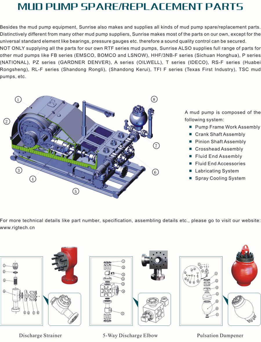
There are two main parts to a mud pump: the fluid end and the power end. The fluid end is where the actual pumping takes place. The components of the fluid end consist of valves, pistons (or plungers), and liners.
Since the fluid end is in constant contact with the material being pumped, most modern designs allow for quick replacement of worn components as needed. This dramatically extends the life of a unit without having to completely replace the pump.
The power end of a mud pump is responsible for taking the input power, typically through a driveshaft, and converting it into the reciprocating motion needed for the pistons. In most mud pump applications, the power end uses a crosshead crankshaft for this conversion.
Rotational power is supplied to the mud pump through an external power source. The power end of the pump converts this rotational energy through a crankshaft to a reciprocating motion that moves the pistons.
Due to the pressure and material being pumped, most mud pump applications can create a lot of vibration. To combat this, many mud pump applications incorporate pulsation dampeners. These are typically used on both suction and discharge sides of the pump.
In some cases, a positive displacement pump may pull the fluids at a pressure lower than its vapor pressure. When this happens, damaging cavitation can take place. In these cases, a charge pump might be required at the inlet side to maintain a positive pressure on the suction stream.
When selecting a mud pump, there are two main parameters to be used, pressure and displacement. Pressure is the net pumping pressure that the pump can safely provide. The requirement for pressure increases as the drilling depth and fluid (or slurry) viscosity increases.
Displacement is the volume of fluid that the pump can transfer within a given time period. In most applications, this is rated as discharged liters per minute.
Mud pumps are ideal wherever a lot of fluid needs to be pumped under high pressure. They are considered an essential part of most oil well drilling rigs. Mud pumps can deliver high concentration and high viscosity slurry in a stable flow, making them adaptable to many uses.
Mud pumps are an invaluable tool when high pressure and high viscosity fluids are needing to be transferred. Mader Electric, Inc. specializes in mud pump repair and installation, as well as pump training. Contact us to see how we can help with your pumping needs.
The 2,200-hp mud pump for offshore applications is a single-acting reciprocating triplex mud pump designed for high fluid flow rates, even at low operating speeds, and with a long stroke design. These features reduce the number of load reversals in critical components and increase the life of fluid end parts.
The pump’s critical components are strategically placed to make maintenance and inspection far easier and safer. The two-piece, quick-release piston rod lets you remove the piston without disturbing the liner, minimizing downtime when you’re replacing fluid parts.
A properly serviced pulsation dampener is critical for your mud pumps’ efficiency, safety, and performance. Unfortunately, there aren’t many resources available to educate personnel on executing safe and effective servicing procedures. Please review the following steps with your personnel for safe pulsation dampener maintenance.

The drilling industry has roots dating back to the Han Dynasty in China. Improvements in rig power and equipment design have allowed for many advances in the way crude oil and natural gas are extracted from the ground. Diesel/electric oil drilling rigs can now drill wells more than 4 miles in depth. Drilling fluid, also called drilling mud, is used to help transfer the dirt or drill cuttings from the action of the drilling bit back to the surface for disposal. Drill cuttings can vary in shape and size depending on the formation or design of the drill bit used in the process.
Watch the video below to see how the EDDY Pump outperforms traditional pumps when it comes to high solids and high viscosity materials commonly found on oil rigs.
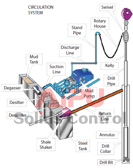
The fluid is charged into high-pressure mud pumps which pump the drilling mud down the drill string and out through the bit nozzles cleaning the hole and lubricating the drill bit so the bit can cut efficiently through the formation. The bit is cooled by the fluid and moves up the space between the pipe and the hole which is called the annulus. The fluid imparts a thin, tough layer on the inside of the hole to protect against fluid loss which can cause differential sticking.
The fluid rises through the blowout preventers and down the flowline to the shale shakers. Shale shakers are equipped with fine screens that separate drill cutting particles as fine as 50-74 microns. Table salt is around 100 microns, so these are fine cuttings that are deposited into the half-round or cuttings catch tank. The drilling fluid is further cleaned with the hydro-cyclones and centrifuges and is pumped back to the mixing area of the mud tanks where the process repeats.
The drill cuttings contain a layer of drilling fluid on the surface of the cuttings. As the size of the drill cuttings gets smaller the surface area expands exponentially which can cause rheological property problems with the fluid. The fluid will dehydrate and may become too thick or viscous to pump so solids control and dilution are important to the entire drilling process.
One of the most expensive and troubling issues with drilling operations is the handling, processing, and circulation of drilling mud along with disposing of the unwanted drill cuttings. The drilling cuttings deposited in the half round tank and are typically removed with an excavator that must move the contents of the waste bin or roll-off box. The excavators are usually rented for this duty and the equipment charges can range from $200-300/day. Add in the cost for the day and night manpower and the real cost for a single excavator can be as much as $1800/day.
Using the excavator method explained above, the unloading of 50 barrels of drill cuttings from the half round can take as long as two hours. This task is mostly performed by the solids control technicians. The prime duty for the solids control technicians is to maintain the solids control equipment in good working order. This involves maintenance for the equipment, screen monitoring and changing, centrifuge adjustments, and retort testing to prepare a daily operational summary of the solids control program.
Offshore drilling rigs follow a similar process in which the mud is loaded into empty drums and held on the oil platform. When a certain number of filled drums is met, the drums are then loaded onto barges or vessels which take the drilling mud to the shore to unload and dispose of.
Oil field drilling operations produce a tremendous volume of drill cuttings that need both removal and management. In most cases, the site managers also need to separate the cuttings from the drilling fluids so they can reuse the fluids. Storing the cuttings provides a free source of stable fill material for finished wells, while other companies choose to send them off to specialty landfills. Regardless of the final destination or use for the cuttings, drilling and dredging operations must have the right high solids slurry pumps to move them for transport, storage, or on-site processing. Exploring the differences in the various drilling fluids, cutting complications, and processing options will reveal why the EDDY Pump is the best fit for the job.
The Eddy Pump is designed to move slurry with solid content as high as 70-80 % depending on the material. This is an ideal application for pumping drill cuttings. Drill cuttings from the primary shakers are typically 50% solids and 50% liquids. The Eddy Pump moves these fluids efficiently and because of the large volute chamber and the design of the geometric rotor, there is very little wear on the pump, ensuring long life and greatly reduced maintenance cost for the lifetime of the pump.
plumbed to sweep the bottom of the collection tank and the pump is recessed into a sump allowing for a relatively clean tank when the solids are removed. The Eddy Pump is sized to load a roll-off box in 10-12 minutes. The benefit is cuttings handling is quicker, easier, safer, and allows for pre-planning loading where the labor of the solids control technician is not monopolized by loading cuttings. Here, in the below image, we’re loading 4 waste roll-off bins which will allow the safe removal of cuttings without fear of the half-round catch tank running over.
Mud cleaning systems such as mud shaker pumps and bentonite slurry pumps move the material over screens and through dryers and centrifuges to retrieve even the finest bits of stone and silt. However, the pump operators must still get the raw slurry to the drill cuttings treatment area with a power main pump. Slurry pumps designed around the power of an Eddy current offer the best performance for transferring cuttings throughout a treatment system.
Options vary depending on whether the company plans to handle drill cuttings treatment on-site or transport the materials to a remote landfill or processing facility. If the plan is to deposit the cuttings in a landfill or a long-term storage container, it’s best to invest in a pump capable of depositing the material directly into transport vehicles. Most dredging operations rely on multiple expensive vacuum trucks, secondary pumps, and extra pieces of equipment.
Using an EDDY Pump will allow a project to eliminate the need for excavators/operators to load drill cuttings, substantially lowering both labor and heavy equipment costs. The EDDY Pump also allows a company to eliminate vacuum trucks once used for cleaning the mud system for displacing fluids. Since the pump transfers muds of all types at constant pressure and velocity throughout a system of practically any size, there’s little need for extra equipment for manual transfer or clean up on the dredge site.
The EDDY Pump can fill up a truck in only 10 minutes (compared to an hour) by using a mechanical means such as an excavator. For this reason, most companies can afford one piece of equipment that can replace half a dozen other units.
This application for the Eddy Pump has the potential to revolutionize the drilling industry. Moving the excavator out of the “back yard” (the area behind the rig from the living quarters) will make cuttings handling a breeze. Trucking can be easier scheduled during daylight hours saving on overtime and incidences of fatigued driving. Rig-site forklifts can move the roll-off boxes out of the staging area and into the pump loading area. The operator can save money on excavators rental, damages, and keep the technician operating the solids control equipment.
The EDDY Pump is ideal for drilling mud pump applications and can be connected directly onto the drilling rigs to pump the drilling mud at distances over a mile for disposal. This eliminates the need for costly vacuum trucks and also the manpower needed to mechanically move the drilling mud. The reasons why the EDDY Pump is capable of moving the drilling mud is due to the hydrodynamic principle that the pump creates, which is similar to the EDDY current of a tornado. This tornado motion allows for the higher viscosity and specific gravity pumping ability. This along with the large tolerance between the volute and the rotor allows for large objects like rock cuttings to pass through the pump without obstruction. The large tolerance of the EDDY Pump also enables the pump to last many times longer than centrifugal pumps without the need for extended downtime or replacement parts. The EDDY Pump is the lowest total life cycle pump on the market.

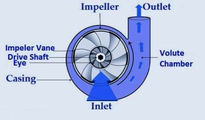
A centrifugal pump is a mechanical device designed to move a fluid by means of the transfer of rotational energy from one or more driven rotors, called impellers. Fluid enters the rapidly rotating impeller along its axis and is cast out by centrifugal force along its circumference through the impeller’s vane tips. The action of the impeller increases the fluid’s velocity and pressure and also directs it towards the pump outlet. The pump casing is specially designed to constrict the fluid from the pump inlet, direct it into the impeller and then slow and control the fluid before discharge.
The impeller is the key component of a centrifugal pump. It consists of a series of curved vanes. These are normally sandwiched between two discs (an enclosed impeller). For fluids with entrained solids, an open or semi-open impeller (backed by a single disc) is preferred (Figure 1).
Fluid enters the impeller at its axis (the ‘eye’) and exits along the circumference between the vanes. The impeller, on the opposite side to the eye, is connected through a drive shaft to a motor and rotated at high speed (typically 500-5000rpm). The rotational motion of the impeller accelerates the fluid out through the impeller vanes into the pump casing.
There are two basic designs of pump casing: volute and diffuser. The purpose in both designs is to translate the fluid flow into a controlled discharge at pressure.
In a volute casing, the impeller is offset, effectively creating a curved funnel with an increasing cross-sectional area towards the pump outlet. This design causes the fluid pressure to increase towards the outlet (Figure 2).
The same basic principle applies to diffuser designs. In this case, the fluid pressure increases as fluid is expelled between a set of stationary vanes surrounding the impeller (Figure 3). Diffuser designs can be tailored for specific applications and can therefore be more efficient. Volute cases are better suited to applications involving entrained solids or high viscosity fluids when it is advantageous to avoid the added constrictions of diffuser vanes. The asymmetry of the volute design can result in greater wear on the impeller and drive shaft.
There are two main families of pumps: centrifugal and positive displacement pumps. In comparison to the latter, centrifugal pumps are usually specified for higher flows and for pumping lower viscosity liquids, down to 0.1 cP. In some chemical plants, 90% of the pumps in use will be centrifugal pumps. However, there are a number of applications for which positive displacement pumps are preferred.
The efficient operation of a centrifugal pump relies on the constant, high speed rotation of its impeller. With high viscosity feeds, centrifugal pumps become increasingly inefficient: there is greater resistance and a higher pressure is needed to maintain a specific flow rate. In general, centrifugal pumps are therefore suited to low pressure, high capacity, pumping applications of liquids with viscosities between 0.1 and 200 cP.
Slurries such as mud, or high viscosity oils can cause excessive wear and overheating leading to damage and premature failures. Positive displacement pumps often operate at considerably lower speeds and are less prone to these problems.
Any pumped medium that is sensitive to shearing (the separation of emulsions, slurries or biological liquids) can also be damaged by the high speed of a centrifugal pump’s impeller. In such cases, the lower speed of a positive displacement pump is preferred.
A further limitation is that, unlike a positive displacement pump, a centrifugal pump cannot provide suction when dry: it must initially be primed with the pumped fluid. Centrifugal pumps are therefore not suited to any application where the supply is intermittent. Additionally, if the feed pressure is variable, a centrifugal pump produces a variable flow; a positive displacement pump is insensitive to changing pressures and will provide a constant output. So, in applications where accurate dosing is required, a positive displacement pump is preferred.
Centrifugal pumps are commonly used for pumping water, solvents, organics, oils, acids, bases and any ‘thin’ liquids in both industrial, agricultural and domestic applications. In fact, there is a design of centrifugal pump suitable for virtually any application involving low viscosity fluids.
A centrifugal pump operates through the transfer of rotational energy from one or more driven rotors, called impellers. The action of the impeller increases the fluid’s velocity and pressure and directs it towards the pump outlet. With its simple design, the centrifugal pump is well understood and easy to operate and maintain.
Centrifugal pump designs offer simple and low cost solutions to most low pressure, high capacity pumping applications involving low viscosity fluids such as water, solvents, chemicals and light oils. Typical applications involve water supply and circulation, irrigation, and the transfer of chemicals in petrochemical plants. Positive displacement pumps are preferred for applications involving highly viscous fluids such as thick oils and slurries, especially at high pressures, for complex feeds such as emulsions, foodstuffs or biological fluids, and when accurate dosing is required.
Drilling consumables such as mud pump systems and their components can drastically increase your uptime while reducing costs and health/safety/environmental (HSE) risks. To support your drilling needs, Forum’s patented P-Quip® mud pump system offers a single-source solution that integrates high-quality fluid end components for maximum longevity and performance.
With more than 20 years of successful operation in severe environments, P-Quip offers a proven track record for the lowest cost of ownership in the industry. As part of our commitment to quality, our mud pump parts use patented Banded Bore™ technology that significantly reduces stress concentrations and leads to longer module life.
One of Forum’s most committed core values is that “no one gets hurt,” and the P-Quip system is designed to support that principle. Streamlined and easy to use, it reduces or eliminates the need for manual force during maintenance, shrinking the time needed to replace high-use components and minimizing safety risks.


 8613371530291