
nabors drilling mud pump pricelist

Managed Pressure Drilling (MPD) is an adaptive process used to more precisely control the annular pressure profile throughout the wellbore while drilling. Converting conventional atmospheric drilling to a closed circulating loop system enables the driller to optimize mud weight and rate of penetration (ROP), more quickly detect influx and fluid loss, and discriminate wellbore ballooning and breathing. This results in lower mud product cost, less stuck pipe, and potentially fewer casing strings.
The MPD process is executed by controlling flow conditions to maintain bottom-hole pressure according to a modeled pore pressure and fracture gradient drilling window. While the benefits of conventional MPD techniques are well known offshore, the economics of engineering, mobilization and rig-up, and additional specialized personnel requirements are not supported in cost-sensitive drilling programs such as unconventional land drilling.
Nabors’ fit-for-purpose MPD equipment and integrated rig services enables a new concept to leverage today’s advanced land rig infrastructure including drives, manifolds, tanks, pumps, and gas handling equipment. Engineering and integrating MPD capabilities into the rig with unique automated workflows unlocks advantages in capital requirements, eliminates the need for pre-job surveys and engineering, and minimizes high mobilization and rig-up costs.
Through the advanced integration and automation of MPD services, the need for third-party service providers is also eliminated. Benefits include increased safety, less HSE exposure, lower cost, reduced pad footprint, more efficient rig moves, and more transparent performance analytics. For all of these reasons, scalability of MPD services is now more cost-effective for land drilling operations.

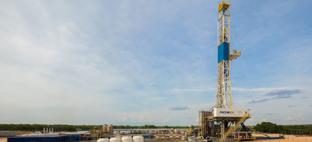
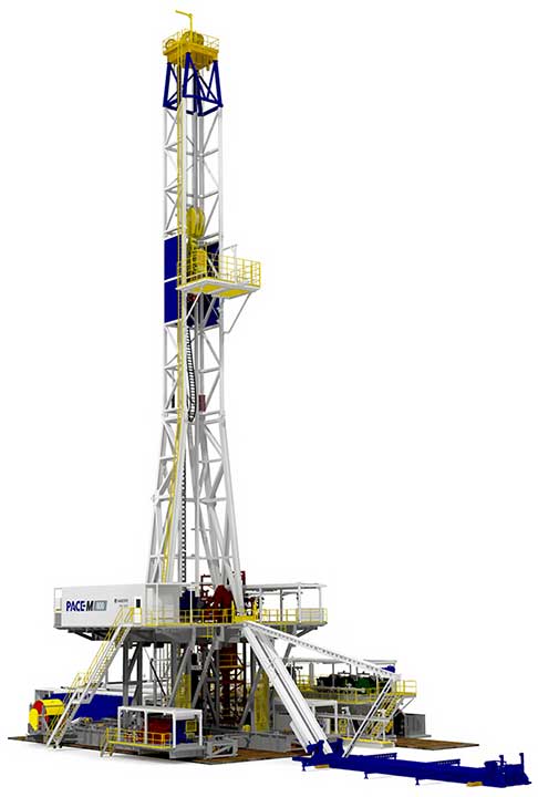
Designed to deliver maximum drilling performance, the PACE®-M800 rig further enhances drilling efficiencies and reduces flat time. Its simplified design enables faster, more advanced walking capabilities and quicker rig-up and rig-down times to reduce move times and lower drilling costs.
When drilling laterals at or greater than 7,500 feet, the PACE®-M800 rig’s racking capacity eliminates the need to lay down drill pipe between wells on the same pad.
It provides the required pressure to maximize rate of penetration (ROP) while running rotary steerable systems and during extended-reach laterals with conventional mud motors.
The PACE®-M800 rig also features faster, more advanced walking capabilities for multi-well pad drilling. It is ideal for drilling up to four wells per pad and moves twice as fast as the PACE®-X800 rig. Features include:

The Canrig® Sigma 500-ton top drive is the next generation top drive, completely reimagined to endure the harshest drilling conditions while operating with the highest continuous torque in its class. Designed to endure the harshest drilling conditions, this all-new, innovative top drive provides more power, performance and torque density than ever before, while enabling greater automation and remote-control capabilities – both at the surface and downhole.
Nabors’ SunDowner is capable of being off-loaded and assembled on an offshore platform in a single day…from sunup to sundown. The short rig-up time results in significant mobilization cost savings.
With over 20 years of experience in designing custom solutions for the oilfield industry, engineers are available to integrate top drives, catwalks, casing running tools or other equipment into any desired rig, including rigs of the future or older classes of rigs ready to see a new age of drilling
Canrig’s range of top drives allows for the selection of a hydraulic or an electric powered unit. Each motor class comes with its own set of benefits which can be reviewed to select which option is more appropriate for a particular drilling environment.
Canrig manufactures, markets and services a full range of electric top drive systems for most land and offshore rigs. This includes top drives in every size and configuration to meet any drilling application whether marine, desert, jungle or arctic environments.
Nabors’ Blue Force® mud motors are customized to specific specifications, built to withstand all drilling fluid types and temperatures, and can help reduce non-productive time.
As pad drilling solutions continue to evolve and improve, walking rigs with crane-less rig-up are quickly becoming a typical feature on location. The Canrig® PadWalker™ was created to support multi-well pad drilling.
Canrig’s wireless torque, turn and tension sensor, the TesTORK® sub, delivers high speed, precise data over a secure wireless connection. Designed for ease of use and field robustness, the TesTORK® sub meets the demands of tubular services companies and drilling contractors alike.
Nabors’ fit-for-purpose managed pressure drilling (MPD) equipment and integrated MPD-Ready® drilling rig maximizes efficiencies and makes MPD services more scalable and cost-effective for unconventional land drillers.
In addition to enhancing the safety of drill floor activities, Nabors offers a fully automated drill floor robot system that reduces the non-productive time, noise, energy consumption and emissions typically associated with manual onshore and/or offshore drilling operations.
The Canrig® climate-controlled driller’s cabin provides integrated joystick control utilizing PLC technology. Touch-screen controls provide enhanced monitoring, control of rig equipment and visibility of drilling parameters.
Nabors offers the FracView® high-resolution LWD imager in 4.75 and 6.5 in collar sizes covering borehole diameter ranges from 5.875 to 9.5 inches. FracView was the first commercially available LWD borehole imager demonstrated to operate in long horizontal wells drilled with oil-based mud.
Key FeaturesDeepView Log Viewer capable of viewing and analysis of large volume high resolution drilling dynamics and imaging data in both time and depth domain
Nabors offers the SpectraView™ LWD spectral/azimuthal gamma ray tools capable of covering borehole sizes from 5.875 to 9.5 inches. The tool measures and records naturally occurring gamma radiation from surrounding formations during wellbore drilling.
Nabors offers the FracView® high-resolution LWD imager in 4.75 and 6.5 in collar sizes covering borehole diameter ranges from 5.875 to 9.5 inches. FracView was the first commercially available LWD borehole imager demonstrated to operate in long horizontal wells drilled with oil-based mud.
Nabors’ Blue Force® mud motors are customized to specific specifications, built to withstand all drilling fluid types and temperatures, and can help reduce non-productive time.
Capable of drilling up to eight laterals from a single wellbore, Nabors’ unique coiled tubing/stem drilling rig, CDR2-AC, was designed to help a major operator more effectively work over old wells and boost production in Alaska’s Kuparuk field.
A Side-Saddle® rig is ideal for batch drilling because it can drill the surface along one row of wells, walk to the adjacent row and repeat the same tasks using the same drilling mud.
Equipped with specially trained drillers, drilling performance software and reliable measurement while drilling (MWD) telemetry, Nabors Directional-Ready™ rigs include integrated downhole equipment and directional drilling instrumentation to enable high-fidelity surveying and precise placement in productive targets of longer lateral wellbores.
Key FeaturesDrillers working on Nabors Directional-Ready™ rigs are trained in directional theory, automated HMI sequences, BHA makeup and advanced wellbore placement operations
Nabors MPD-Ready® rigs feature integrated hardware and software components, and required flow paths, to ascertain the downhole pressure environment limits and manage annular hydraulic pressure during drilling operations. All equipment skids with rig, eliminating non-productive time when moving between wells for multi-well pad drilling.
Nabors offers cementing and casing accessories, including hydroform centralizers, Multi-Lobe Torque™ (MLT®) rings, reaming shoes and cementing solutions.
Nabors’ automated tubular service technology brings significant improvements in safety, performance, reliability and efficiency during casing drilling and tubular running operations.
The SmartPLAN™ tool seamlessly manages both the operator’s and drilling contractor’s workflows to deliver digital drilling recipes that optimize efficiency and improve performance.
Proprietary automated drilling activity sequencer that optimizes rig processes. Proven to consistently improve connection times, increase one run laterals and decrease unplanned trips, the SmartDRILL™ system drives scalable cost reduction and improved drilling performance. Workflows are digitalized to improve procedural adherence and ensure that best practices are being configured for future wells.
Nabors SmartROS™ automates many repetitive drilling tasks while integrating data from both downhole tools and surface systems. Automating these functions allows the driller to follow the customer’s well plan with a higher level of precision and operational excellence.
Nabors REVit® technology features advanced top drive automation that eliminates stick slip, a common mode of vibration that limits drilling performance.
The ROCKit® Suite significantly increases rate of penetration (ROP) by rocking pipe and delivering ideal weight to bit. It promotes improved toolface control by allowing fine adjustments while still drilling ahead, reducing the need for lubricants and other friction-reducing additives. Drillers save time by quickly setting toolface orientation.
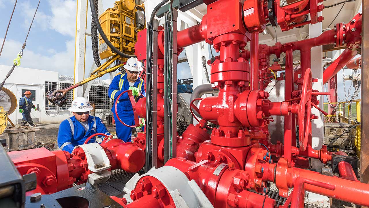
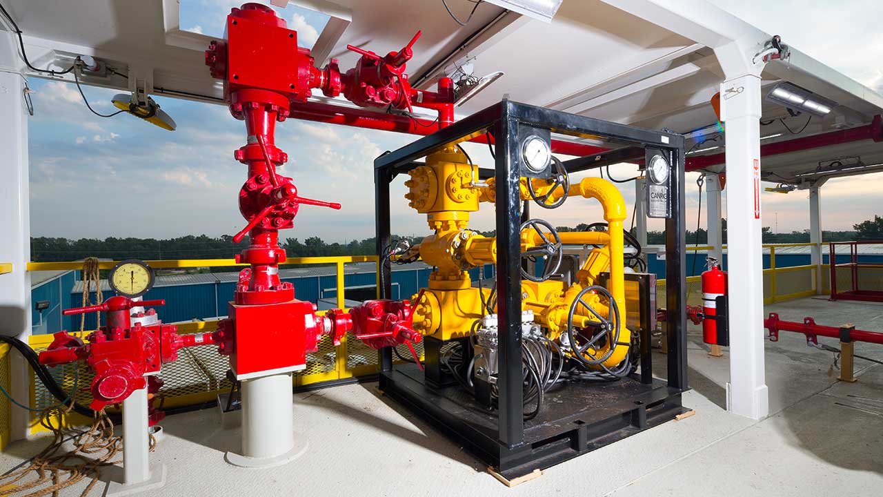
Nabors offers remote control choke technology to help operators meet the challenges of well pressure control, while reducing costs and enhancing environmental risk and wellsite safety.
This integrated offering includes rotating control devices (RCDs) for the onshore unconventional market. RCDs are utilized for pressure management during drilling for the purpose of making a seal around the drillstring while the drillstring rotates.
Nabors provides BOP installation and inspection as well as API-compliant, field-proven testing of BOP components in compliance with industry standards.
Non-Stop Driller™ is a sub-based constant circulation system that allows the continuous circulation of drill fluids downhole while making or breaking drill pipe connections, enabling improved wellbore stability and hole cleaning, reduced risks of influx and optimum drilling performance.
The SmartSLIDE™ system integrates critical downhole information needed for directional drilling and then automatically implements corrective instructions and steering logic during slide drilling operations.
Nabors’ SmartNAV™ platform is an automated directional drilling decision-making system that visualizes the downhole positions of the drill bit and the planned well path and automatically generates instructions to keep the well on course.
The PACE®-R800 rig utilizes technology optimized for drilling automation with Nabors Rigtelligent® control system. The rack and pinion technology enables the precise control of block position required for advanced automati
As lateral lengths continue to increase, drillers need a rig with more power and greater tripping speed. Nabors PACE®-M800 rig features innovative advanced technologies that provide both.
When drilling laterals at or greater than 7,500 feet, the PACE®-M800 rig’s racking capacity eliminates the need to lay down drill pipe between wells on the same pad.
With over 20 years of experience in designing custom solutions for the oilfield industry, engineers are available to integrate top drives, catwalks, casing running tools or other equipment into any desired rig, including rigs of the future or older classes of rigs ready to see a new age of drilling

A high percentage of mud motors are considered to be run out of spec by industry standards. The challenge has been to build a reliable motor that can withstand the stresses of more weight on bit, differential pressure, and rotary RPM.
The durability of Canrig’s top drives is second to none. Available in sizes ranging from 150-ton to 1000-ton units, each unit comes with many different features to optimize drilling efficiency and safety.
Canrig’s commitment to drilling automation and efficiency also resulted in the development of a line of intelligent top drive accessories. Each blends innovation with excellence in engineering:
If you are supplying pump supplies, you can find the most favorable prices at Alibaba.com. Whether you will be working with piston type or diaphragm type systems, reciprocating or centrifugal, Alibaba.com has everything you need. You can also shop for different sizes drilling mud pump price wholesale for your metering applications. If you operate a construction site, then you could need to find some concrete pump solutions that you can find at affordable rates at Alibaba.com. Visit the platform and browse through the collection of submersible and inline pump system, among other replaceable models.
A drilling mud pump price comes in different makes and sizes, and you buy the tool depending on the application. The pump used by a filling station is not the one you use to fill up your tanks. There are high flow rate low pressure systems used to transfer fluids axially. On the other hand, you can go with radial ones dealing with a low flow rate and high-pressure fluid. The mixed flow pump variety combines radial and axial transfer mechanisms and works with medium flow and pressure fluids. Depending on what it will be pumping, you can then choose the drilling mud pump price of choice from the collection at Alibaba.com.
Alibaba.com has been an excellent wholesale supplier of drilling mud pump price for years. The supply consists of a vast number of brands to choose from, comes in different sizes, operations, and power sources. You can get a pump for residential and large commercial applications from the collection. Whether you want a water pump for your home, or run a repair and maintenance business, and need a supply of dr drill mud pump prices, you can find the product you want from the vast collection at Alibaba.com.ther it is for refrigeration, air conditioning, transfer, or a simple car wash business, anything you want, Alibaba.com has it.

“Downhole motor technology, along with reaming-while-drilling and electromagnetic measuring-while-drilling (MWD) technologies have been critical for us in exploiting the Bakken,” said Mark R. Williams, senior vice president of exploration and development for Whiting Petroleum, one of the three most active operators in the Bakken and one of two companies that made the first commercial discoveries in the play back in 2005. Over the past six months, Whiting produced 90,000 bbls of oil from the Bakken and associated Three Forks play.
“The standardization of the 1,600-hp and larger mud pumps is allowing us to drill wells in as short a time as 12 days and increase our rates of penetration (ROP) dramatically,” Mr Williams said. “Reaming-while-drilling technology eliminates the need for us to spend two to three days cleaning out the hole when we finish drilling, and electromagnetic MWD tools allow us to measure various properties of the well while we’re drilling, which results in a savings of another one to two days.”
Encompassing much of North Dakota, parts of South Dakota and Montana and extending into Saskatchewan and Manitoba, Canada, the Williston Basin was deposited in the late Devonian and early Mississippian periods. The basin also includes the shallower Tyler play, where the first horizontal test using Bakken drilling technology is planned for Q4 this year; the deeper Mission Canyon and Red River plays; Duperow; Winnipegosis and Winnipeg Group. Operators also have conducted exploratory drilling in the Exshaw formation in northwestern Montana and Alberta, a region formed at the same time as the Williston Basin with very Bakken-like organic shale.
“From a reservoir engineering standpoint, the reservoir is very tight with low porosity and low permeability, requiring horizontal drilling and multi-stage fracturing to make it produce,” he explained. The Bakken formation also includes the underlying Three Forks interval, where a number of companies are producing, and the Lodgepole formation on top. A newly identified thin zone, the Pronghorn (formerly known as the Sanish), lies below the Lower Bakken and is being explored by some operators.
Whiting has drilled 140 wells in the play, initially drilling short laterals of 5,000 ft. The company quickly embarked on drilling longer single laterals with staged completions, which has proved to be a game-changer in the Bakken, Mr Williams said. “Over time, we began realizing that we got better results with more stages,” he said. “We are now typically running 40 stages per well.”
On average, Bakken wells feature a vertical section of 10,000 ft with laterals from 9,500 to 10,000 ft for a “perfect L shape,” Mr Williams continued. Operators can hold a 2-sq-mile lease space by drilling a single well and establishing production, then return several months later, put a pad at one end of the unit and drill several wells, often alternating between the Middle Bakken and the underlying Three Forks zone.
Rigs that can move long distances from county to county are optimum for drilling the initial held-by-production (HBP) wells, Mr Williams explained. “These rigs need to be able to break down into as few truckloads as possible because trucking in the region is hard to get and expensive. For the subsequent pad drilling, we need rigs that can skid easily from well to well.”
Whiting is also doing some production in the Red River and Mission Canyon pools, located near the southern end of the basin and in some areas, extending over the Montana-North Dakota state line. “For the most part, this is conventional drilling, and we’re using older, vertical-style rigs to find the reserves. However, the rigs need to be mobile and, ideally, truck-mounted,” Mr Williams said. Operators also are testing horizontal drilling applications for drilling the 11,000-ft vertical wells in these plays.
Globe Energy Serviceshas designed a five-axle land rig providing quick rig-up/rig-down operations, a mast with 116 ft of clearance and an adjustable drilling floor. Two of the new Mustang 600 Class rigs have been deployed to the Permian Basin for unconventional oil shale wells, and a third is working in the Kilgore gas field in East Texas. A fourth rig will be added this fall, also to the Kilgore field. Opportunities to deploy additional rigs to the Bakken and Eagle Ford are possible as well, according to Johnny Slaughter, vice president of well services. “The taller mast is a key element of this new rig, because the operator can rig up and clear the wellhead control equipment from the ground instead of a ramp,” Mr Slaughter said.
For drilling contractors, the Bakken has served as a catalyst for designing rigs that deliver the horsepower, mobility and automation that are driving production. With 57 active rigs out of a total Bakken rig count of 230, Nabors Drilling USA (NDUSA) is the largest contractor in the play. The company’s PACE-B (programmable AC electric) Series rig, a box-on-box, 1,500-hp model with a walking system, was built specifically for the Bakken and has consistently drilled 21,000-ft wells in less than half the time of most rigs in the basin, said Joey Husband, senior vice president and general manager of NDUSA.
Nabors currently has 25 PACE-B Series rigs in the region and will add four more later this year. “This rig is well suited for the Bakken, which is unique because the local infrastructure is under a lot of pressure,” Mr Husband said. “Drilling generates a lot of other activity, such as trucking and transportation, water delivery, fuel consumption, and delivery of parts and supplies.”
The pump horsepower and hydraulic torque specifications of the rig’s top drive system are designed with enough capacity to reach 21,000-plus ft well depths with long horizontal sections. The box-on-box design is climate-controlled with an enclosed system to allow for drilling in the winter. Dual fuel power systems take advantage of the natural gas available on site, reducing diesel fuel requirements.
“The beauty of this rig is that the walking system allows it to line up perfectly over each well, which allows for more efficient drilling,” Mr Husband said. “This precludes problems sometimes seen with conventional rail systems where conductor pipes are pre-set prior to the rig arriving on location and slightly off center from each other.”
For multi-well pads, the walking system allows a full setback of pipe to be left in the derrick, with stands made up, so the rig can walk to the next well and immediately start drilling. “This saves time and allows for simultaneous operations on the rig, he added. “For our customers who are drilling pads with up to seven or eight wells, we can quickly and efficiently walk down the well row as we drill.”
“Like most unconventional plays, the Bakken features tight oil or gas formations, and every operator has a different way of drilling the hole – some are vertical, some horizontal and some are S curves,” said Jay Thiessen, onshore global business development manager. “In many cases, operators are going into areas where transportation is difficult or road conditions don’t allow wide loads. Sometimes the formations require higher-than-than usual horsepower, more hydraulics for pumping or have high-pressure zones that require a higher-pressure blowout preventer (BOP) stack. In cases of pad drilling, the spacing is often very tight.”
But while drilling plans vary, a common theme in the Bakken is that operators are drilling long, extended laterals, which is why pad drilling is so prevalent, saidNiels Meissner, product technical manager for NOV. “For any unconventional tight oil or gas formation, in order to maximize the productivity of the well, an operator must maximize contact of the borehole with the productive part of the formation,” he said.
The company is designing rigs and equipment packages that are increasingly automated. “We’re looking at more drilling solutions that minimize personnel and that translate to more automation,” Mr Thiessen said. Features are currently still more semi-automatic in nature, keeping a person in charge versus relying on robotics. “For example, we’re developing a program for one customer where the driller pushes a button to initiate both the tripping and drilling cycles. More autonomous control systems, like our NOVOS system, will be coming onto the scene in the next few years, in the Bakken and elsewhere.”
From a drilling performance perspective, the company has two top drive software enhancements that can be installed on any rig equipped with an NOV top drive, Mr Meissner explained. SoftSpeed is a top drive control software upgrade that reduces or eliminates stick-slip, which often occurs when drilling extended-reach or long lateral wells. Another top drive enhancement, Twister, enables the top drive to put minor oscillations in the drill string to reduce friction when slide drilling.
“The technology also aids the directional driller in maintaining tool face, or orientation of his directional drilling tools,” he said. “For example, the driller can input a certain desired rotational angle into the system, and Twister will automatically compute and rotate the top drive a specific degree to achieve the desired angle of rotation downhole.”
In line with the trend toward multi-well pads, Marathon Oilis drilling on more two-well and four-well pad locations and plans to go as high as six to eight wells per pad, or more, using modern rig technology such as Helmerich & Payne’s (H&P) FlexRig 3s, said Jim Thompson, Marathon’s drilling and completions manager for the Bakken. “The multi-well pads limit the footprint and the impact on the infrastructure and communities,” he explained. “In some areas, especially the Badlands, the topography is such that the only way we can effectively develop certain acreage is to drill from a multi-well pad.”
Marathon Oil is seeing average measured well depths of approximately 20,500 ft; however, in the Badlands around the Missouri River and Lake Sakakawea, operators are drilling longer, 2 ½-section wells and looking at three-section wells for depths from 22,000 to 26,000 ft. “The geography of the area necessitates the need for longer laterals,” Mr Thompson said. “There also are ranges where we need extended lengths to drill under the lake.”
H&P has 35 rigs operating in the Bakken, approximately 65% of which are FlexRig3s, which is designed to accommodate a single-direction skid system that allows the rig to drill either a single-well pad or a single row of wells on a pad, said David Millwee, H&P’s vice president for performance solutions. The company has yet to venture into the basin’s experimental formations. “When we first arrived in the Bakken in 2006, we were drilling 16,000- to 18,000-ft measured depth wells with laterals of 6,000 to 8,000 ft,” he said. “We’re now drilling 10,000- to 12,000-ft laterals and recently extended to 14,000-ft laterals.”
H&P is also running its Flex4S rigs in the area. These rigs have similar design features as the Flex3 but are built specifically for pad drilling and incorporate an X/Y skidding system to be used for multi-well pad drilling in the Bakken.
Introduced in 1998, the FlexRig is now in its fifth generation. “The Flex3 has been a workhorse for H&P since 2002, improving drilling times and reducing costs for operators,” Mr Millwee said. “The characteristics of the rig are set up very well to drill the 22,000-ft and greater measured well depths we’re now seeing in the Bakken.”
PACE is a registered term of Nabors Industries. IDEAL, NOVOS, SteelToe, Twister and SoftSpeed are trademarked terms of National Oilwell Varco. FlexRig is a trademarked term of Helmerich & Payne.
At Sigma Drilling Technologies, we utilize out-of-the-box thinking and cutting edge innovation. From our revolutionary pulsation control systems, to our one of a kind performance boosting solutions, Sigma delivers unsurpassed technology. Helping businesses succeed by getting the most out their equipment investment is our goal. Let us partner with your team to help maximize your production output, enhance equipment investment, and place you at the forefront of industry advancements.
Subterranean “sliding” drilling operation typically involves rotating a drill bit on a downhole motor at the remote end of a drill pipe string. Drilling fluid forced through the drill pipe rotates the motor and bit. The assembly is directed or “steered” from a vertical drill path in any number of directions, allowing the operator to guide the wellbore to desired underground locations. For example, to recover an underground hydrocarbon deposit, the operator may drill a vertical well to a point above the reservoir and then steer the wellbore to drill a deflected or “directional” well that penetrates the deposit. The well may pass horizontally through the deposit. Friction between the drill string and the bore generally increases as a function of the horizontal component of the bore, and slows drilling by reducing the force that pushes the bit into new formations.
Such directional drilling requires accurate orientation of a bent segment of the downhole motor that drives the bit. Rotating the drill string changes the orientation of the bent segment and the toolface. To effectively steer the assembly, the operator must first determine the current toolface orientation, such as via measurement-while-drilling (MWD) apparatus. Thereafter, if the drilling direction needs adjustment, the operator must rotate the drill string to change the toolface orientation.
Conventionally, such toolface orientation requires the operator to manipulate the drawworks brake, and rotate the rotary table or top drive quill to find the precise combinations of hook load, mud motor differential pressure, and drill string torque, to position the toolface properly. Each adjustment has different effects on the toolface orientation, and each must be considered in combination with other drilling requirements to drill the hole. Thus, reorienting the toolface in a bore is very complex, labor intensive, and often inaccurate.
Referring to FIG. 1, illustrated is a schematic view of apparatus 100 demonstrating one or more aspects of the present disclosure. The apparatus 100 is or includes a land-based drilling rig. However, one or more aspects of the present disclosure are applicable or readily adaptable to any type of drilling rig, such as jack-up rigs, semisubmersibles, drill ships, coil tubing rigs, well service rigs adapted for drilling and/or re-entry operations, and casing drilling rigs, among others within the scope of the present disclosure.
Apparatus 100 includes a mast 105 supporting lifting gear above a rig floor 110. The lifting gear includes a crown block 115 and a traveling block 120. The crown block 115 is coupled at or near the top of the mast 105, and the traveling block 120 hangs from the crown block 115 by a drilling line 125. The drilling line 125 extends from the lifting gear to draw works 130, which is configured to reel out and reel in the drilling line 125 to cause the traveling block 120 to be lowered and raised relative to the rig floor 110.
The drill string 155 includes interconnected sections of drill pipe 165, a bottom hole assembly (BHA) 170, and a drill bit 175. The bottom hole assembly 170 may include stabilizers, drill collars, and/or measurement-while-drilling (MWD) or wireline conveyed instruments, among other components. The drill bit 175, which may also be referred to herein as a tool, is connected to the bottom of the BHA 170 or is otherwise attached to the drill string 155. One or more pumps 180 may deliver drilling fluid to the drill string 155 through a hose or other conduit 185, which may be connected to the top drive 140.
The downhole MWD or wireline conveyed instruments may be configured for the evaluation of physical properties such as pressure, temperature, torque, weight-on-bit (WOB), vibration, inclination, azimuth, toolface orientation in three-dimensional space, and/or other downhole parameters. These measurements may be made downhole, stored in solid-state memory for some time, and downloaded from the instrument(s) at the surface and/or transmitted to the surface. Data transmission methods may include, for example, digitally encoding data and transmitting the encoded data to the surface, possibly as pressure pulses in the drilling fluid or mud system, acoustic transmission through the drill string 155, electronically transmitted through a wireline or wired pipe, and/or transmitted as electromagnetic pulses. MWD tools and/or other portions of the BHA 170 may have the ability to store measurements for later retrieval via wireline and/or when the BHA 170 is tripped out of the wellbore 160.
In an exemplary embodiment, the apparatus 100 may also include a rotating blow-out preventer (BOP) 158, such as if the well 160 is being drilled utilizing under-balanced or managed-pressure drilling methods. In such embodiment, the annulus mud and cuttings may be pressurized at the surface, with the actual desired flow and pressure possibly being controlled by a choke system, and the fluid and pressure being retained at the well head and directed down the flow line to the choke by the rotating BOP 158. The apparatus 100 may also include a surface casing annular pressure sensor 159 configured to detect the pressure in the annulus defined between, for example, the wellbore 160 (or casing therein) and the drill string 155.
The apparatus 100 also includes a controller 190 configured to control or assist in the control of one or more components of the apparatus 100. For example, the controller 190 may be configured to transmit operational control signals to the drawworks 130, the top drive 140, the BHA 170 and/or the pump 180. The controller 190 may be a stand-alone component installed near the mast 105 and/or other components of the apparatus 100. In an exemplary embodiment, the controller 190 comprises one or more systems located in a control room proximate the apparatus 100, such as the general purpose shelter often referred to as the “doghouse” serving as a combination tool shed, office, communications center and general meeting place. The controller 190 may be configured to transmit the operational control signals to the drawworks 130, the top drive 140, the BHA 170 and/or the pump 180 via wired or wireless transmission means which, for the sake of clarity, are not depicted in FIG. 1.
The apparatus 100 may additionally or alternatively include a shock/vibration sensor 170 bthat is configured for detecting shock and/or vibration in the BHA 170. The apparatus 100 may additionally or alternatively include a mud motor delta pressure (ΔP) sensor 172 athat is configured to detect a pressure differential value or range across one or more motors 172 of the BHA 170. The one or more motors 172 may each be or include a positive displacement drilling motor that uses hydraulic power of the drilling fluid to drive the bit 175, also known as a mud motor. One or more torque sensors 172 bmay also be included in the BHA 170 for sending data to the controller 190 that is indicative of the torque applied to the bit 175 by the one or more motors 172.
The top drive 140, draw works 130, crown or traveling block, drilling line or dead line anchor may additionally or alternatively include or otherwise be associated with a WOB sensor 140 c(e.g., one or more sensors installed somewhere in the load path mechanisms to detect WOB, which can vary from rig-to-rig) different from the WOB sensor 170 d. The WOB sensor 140 cmay be configured to detect a WOB value or range, where such detection may be performed at the top drive 140, draw works 130, or other component of the apparatus 100.
The detection performed by the sensors described herein may be performed once, continuously, periodically, and/or at random intervals. The detection may be manually triggered by an operator or other person accessing a human-machine interface (HMI), or automatically triggered by, for example, a triggering characteristic or parameter satisfying a predetermined condition (e.g., expiration of a time period, drilling progress reaching a predetermined depth, drill bit usage reaching a predetermined amount, etc.). Such sensors and/or other detection means may include one or more interfaces which may be local at the well/rig site or located at another, remote location with a network link to the system.
Referring to FIG. 2, illustrated is a flow-chart diagram of a method 200 according to one or more aspects of the present disclosure. The method 200 may be performed in association with one or more components of the apparatus 100 shown in FIG. 1 during operation of the apparatus 100. For example, the method 200 may be performed for toolface orientation during drilling operations performed via the apparatus 100.
Referring to FIG. 3, illustrated is a flow-chart diagram of another embodiment of the method 200 shown in FIG. 2, herein designated by reference numeral 202. The method 202 may be performed in association with one or more components of the apparatus 100 shown in FIG. 1 during operation of the apparatus 100. For example, the method 202 may be performed for toolface orientation during drilling operations performed via the apparatus 100.
The BHA 410 may also include a mud motor ΔP sensor 450 that is configured to detect a pressure differential value or range across the mud motor of the BHA 410, and that may be substantially similar to the mud motor ΔP sensor 172 ashown in FIG. 1. The pressure differential data detected via the mud motor ΔP sensor 450 may be sent via electronic signal to the controller 425 via wired or wireless transmission. The mud motor ΔP may be alternatively or additionally calculated, detected, or otherwise determined at the surface, such as by calculating the difference between the surface standpipe pressure just off-bottom and pressure once the bit touches bottom and starts drilling and experiencing torque.
The drawworks 420 includes a controller 490 and/or other means for controlling feed-out and/or feed-in of a drilling line (such as the drilling line 125 shown in FIG. 1). Such control may include directional control (in vs. out) as well as feed rate. However, exemplary embodiments within the scope of the present disclosure include those in which the drawworks drill string feed off system may alternatively be a hydraulic ram or rack and pinion type hoisting system rig, where the movement of the drill string up and down is via something other than a drawworks. The drill string may also take the form of coiled tubing, in which case the movement of the drill string in and out of the hole is controlled by an injector head which grips and pushes/pulls the tubing in/out of the hole. Nonetheless, such embodiments may still include a version of the controller 490, and the controller 490 may still be configured to control feed-out and/or feed-in of the drill string.
The controller 425 is configured to receive one or more of the above-described parameters from the user interface 405, the BHA 410 and the drive system 415, and utilize the parameters to continuously, periodically, or otherwise determine the current toolface orientation. The controller 425 may be further configured to generate a control signal, such as via intelligent adaptive control, and provide the control signal to the drive system 415 and/or the drawworks 420 to adjust and/or maintain the toolface orientation. For example, the controller 425 may execute the method 202 shown in FIG. 3 to provide one or more signals to the drive system 415 and/or the drawworks 420 to increase or decrease WOB and/or quill position, such as may be required to accurately “steer” the drilling operation.
In the exemplary embodiment depicted in FIG. 5A, the at least one processor 520 includes a toolface controller 520 a, and the apparatus 500 aalso includes or is otherwise associated with a plurality of sensors 530. The plurality of sensors 530 includes a bit torque sensor 530 a, a quill torque sensor 530 b, a quill speed sensor 530 c, a quill position sensor 530 d, a mud motor ΔP sensor 530 eand a toolface orientation sensor 530 f. Other embodiments within the scope of the present disclosure, however, may utilize additional or alternative sensors 530. In an exemplary embodiment, each of the plurality of sensors 530 may be located at the surface of the wellbore; that is, the sensors 530 are not located downhole proximate the bit, the bottom hole assembly, and/or any measurement-while-drilling tools. In other embodiments, however, one or more of the sensors 530 may not be surface sensors. For example, in an exemplary embodiment, the quill torque sensor 530 b, the quill speed sensor 530 c, and the quill position sensor 530 dmay be surface sensors, whereas the bit torque sensor 530 a, the mud motor ΔP sensor 530 e, and the toolface orientation sensor 530 fmay be downhole sensors (e.g., MWD sensors). Moreover, individual ones of the sensors 530 may be substantially similar to corresponding sensors shown in FIG. 1 or FIG. 4.
The toolface controller 520 amay compare the actual torque of the quill to the quill torque positive limit received from the corresponding user input 510 a. The actual torque of the quill may be determined utilizing data received from the quill torque sensor 530 b. For example, if the actual torque of the quill exceeds the quill torque positive limit, then the quill drive control signal may direct the quill drive 540 to reduce the torque being applied to the quill. In an exemplary embodiment, the toolface controller 520 amay be configured to optimize drilling operation parameters related to the actual torque of the quill, such as by maximizing the actual torque of the quill without exceeding the quill torque positive limit.
The toolface controller 520 amay alternatively or additionally compare the actual torque of the quill to the quill torque negative limit received from the corresponding user input 510 b. For example, if the actual torque of the quill is less than the quill torque negative limit, then the quill drive control signal may direct the quill drive 540 to increase the torque being applied to the quill. In an exemplary embodiment, the toolface controller 520 amay be configured to optimize drilling operation parameters related to the actual torque of the quill, such as by minimizing the actual torque of the quill while still exceeding the quill torque negative limit.
The toolface controller 520 amay alternatively or additionally compare the actual speed of the quill to the quill speed positive limit received from the corresponding user input 510 c. The actual speed of the quill may be determined utilizing data received from the quill speed sensor 530 c. For example, if the actual speed of the quill exceeds the quill speed positive limit, then the quill drive control signal may direct the quill drive 540 to reduce the speed at which the quill is being driven. In an exemplary embodiment, the toolface controller 520 amay be configured to optimize drilling operation parameters related to the actual speed of the quill, such as by maximizing the actual speed of the quill without exceeding the quill speed positive limit.
The toolface controller 520 amay alternatively or additionally compare the actual speed of the quill to the quill speed negative limit received from the corresponding user input 510 d. For example, if the actual speed of the quill is less than the quill speed negative limit, then the quill drive control signal may direct the quill drive 540 to increase the speed at which the quill is being driven. In an exemplary embodiment, the toolface controller 520 amay be configured to optimize drilling operation parameters related to the actual speed of the quill, such as by minimizing the actual speed of the quill while still exceeding the quill speed negative limit.
The toolface controller 520 amay alternatively or additionally compare the actual orientation (azimuth) of the quill to the quill oscillation positive limit received from the corresponding user input 510 e. The actual orientation of the quill may be determined utilizing data received from the quill position sensor 530 d. For example, if the actual orientation of the quill exceeds the quill oscillation positive limit, then the quill drive control signal may direct the quill drive 540 to rotate the quill to within the quill oscillation positive limit, or to modify quill oscillation parameters such that the actual quill oscillation in the positive direction (e.g., clockwise) does not exceed the quill oscillation positive limit. In an exemplary embodiment, the toolface controller 520 amay be configured to optimize drilling operation parameters related to the actual oscillation of the quill, such as by maximizing the amount of actual oscillation of the quill in the positive direction without exceeding the quill oscillation positive limit.
The toolface controller 520 amay alternatively or additionally compare the actual orientation of the quill to the quill oscillation negative limit received from the corresponding user input 510 f. For example, if the actual orientation of the quill is less than the quill oscillation negative limit, then the quill drive control signal may direct the quill drive 540 to rotate the quill to within the quill oscillation negative limit, or to modify quill oscillation parameters such that the actual quill oscillation in the negative direction (e.g., counter-clockwise) does not exceed the quill oscillation negative limit. In an exemplary embodiment, the toolface controller 520 amay be configured to optimize drilling operation parameters related to the actual oscillation of the quill, such as by maximizing the actual amount of oscillation of the quill in the negative direction without exceeding the quill oscillation negative limit.
The toolface controller 520 amay alternatively or additionally compare the actual orientation of the toolface to the toolface orientation input received from the corresponding user input 510 h. The toolface orientation input received from the user input 510 hmay be a single value indicative of the desired toolface orientation. For example, if the actual toolface orientation differs from the toolface orientation input value by a predetermined amount, then the quill drive control signal may direct the quill drive 540 to rotate the quill an amount corresponding to the necessary correction of the toolface orientation. However, the toolface orientation input received from the user input 510 hmay alternatively be a range within which it is desired that the toolface orientation remain. For example, if the actual toolface orientation is outside the toolface orientation input range, then the quill drive control signal may direct the quill drive 540 to rotate the quill an amount necessary to restore the actual toolface orientation to within the toolface orientation input range. In an exemplary embodiment, the actual toolface orientation is compared to a toolface orientation input that is automated, perhaps based on a predetermined and/or constantly updating plan, possibly taking into account drilling progress path error.
In each of the above-mentioned comparisons and/or calculations performed by the toolface controller, the actual mud motor ΔP and/or the actual bit torque may also be utilized in the generation of the quill drive signal. The actual mud motor ΔP may be determined utilizing data received from the mud motor ΔP sensor 530 e, and/or by measurement of pump pressure before the bit is on bottom and tare of this value, and the actual bit torque may be determined utilizing data received from the bit torque sensor 530 a. Alternatively, the actual bit torque may be calculated utilizing data received from the mud motor ΔP sensor 530 e, because actual bit torque and actual mud motor ΔP are proportional.
One example in which the actual mud motor ΔP and/or the actual bit torque may be utilized is when the actual toolface orientation cannot be relied upon to provide accurate or fast enough data. For example, such may be the case during “blind” drilling, or other instances in which the driller is no longer receiving data from the toolface orientation sensor 530 f. In such occasions, the actual bit torque and/or the actual mud motor ΔP can be utilized to determine the actual toolface orientation. For example, if all other drilling parameters remain the same, a change in the actual bit torque and/or the actual mud motor ΔP can indicate a proportional rotation of the toolface orientation in the same or opposite direction of drilling. For example, an increasing torque or ΔP may indicate that the toolface is changing in the opposite direction of drilling, whereas a decreasing torque or ΔP may indicate that the toolface is moving in the same direction as drilling. Thus, in this manner, the data received from the bit torque sensor 530 aand/or the mud motor ΔP sensor 530 ecan be utilized by the toolface controller 520 in the generation of the quill drive signal, such that the quill can be driven in a manner which corrects for or otherwise takes into account any bit rotation which is indicated by a change in the actual bit torque and/or actual mud motor ΔP.
Moreover, under some operating conditions, the data received by the toolface controller 520 from the toolface orientation sensor 530 fcan lag the actual toolface orientation. For example, the toolface orientation sensor 530 fmay only determine the actual toolface periodically, or a considerable time period may be required for the transmission of the data from the toolface to the surface. In fact, it is not uncommon for such delay to be 30 seconds or more. Consequently, in some implementations, it may be more accurate or otherwise advantageous for the toolface controller 520 ato utilize the actual torque and pressure data received from the bit torque sensor 530 aand the mud motor ΔP sensor 530 ein addition to, if not in the alternative to, utilizing the actual toolface data received from the toolface orientation sensor 530 f.
Referring to FIG. 5B, illustrated is a schematic view of at least a portion of another embodiment of the apparatus 500 a, herein designated by the reference numeral 500 b. Like the apparatus 500 a, the apparatus 500 bis an exemplary implementation of the apparatus 100 shown in FIG. 1 and/or the apparatus 400 shown in FIG. 4, and is an exemplary environment in which the method 200 shown in FIG. 2 and/or the method 202 shown in FIG. 3 may be performed. The apparatus 500 bincludes the plurality of user inputs 510 and the at least one processor 520, like the apparatus 500 a. For example, the user inputs 510 of the apparatus 500 binclude the quill torque positive limit 510 a, the quill torque negative limit 510 b, the quill speed positive limit 510 c, the quill speed negative limit 510 d, the quill oscillation positive limit 510 e, the quill oscillation negative limit 510 f, the quill oscillation neutral point input 510 g, and the toolface orientation input 510 h. However, the user inputs 510 of the apparatus 500 balso include a WOB tare 510 i, a mud motor ΔP tare 510 j, an ROP input 510 k, a WOB input 510 i, a mud motor ΔP input 510 mand a hook load limit 510 n. Other embodiments within the scope of the present disclosure, however, may utilize additional or alternative user inputs 510.
In the exemplary embodiment depicted in FIG. 5B, the at least one processor 520 includes the toolface controller 520 a, described above, and a drawworks controller 520 b. The apparatus 500 balso includes or is otherwise associated with a plurality of sensors 530, the quill drive 540 and a drawworks drive 550. The plurality of sensors 530 includes the bit torque sensor 530 a, the quill torque sensor 530 b, the quill speed sensor 530 c, the quill position sensor 530 d, the mud motor ΔP sensor 530 eand the toolface orientation sensor 530 f, like the apparatus 500 a. However, the plurality of sensors 530 of the apparatus 500 balso includes a hook load sensor 530 g, a mud pump pressure sensor 530 h, a bit depth sensor 530 i, a casing pressure sensor 530 jand an ROP sensor 530 k. Other embodiments within the scope of the present disclosure, however, may utilize additional or alternative sensors 530. In the exemplary embodiment of the apparatus 500 bshown in FIG. 5B, each of the plurality of sensors 530 may be located at the surface of the wellbore, downhole (e.g., MWD), or elsewhere.
The drawworks controller 520 bcompares the current WOB with WOB input data. The current WOB is received from the comparator 520 c, and the WOB input data is received from the corresponding user input 510 i. The WOB input data received from the user input 510 imay be a single value indicative of the desired WOB. For example, if the actual WOB differs from the WOB input by a predetermined amount, then the drawworks drive control signal may direct the drawworks drive 550 to feed cable in or out an amount corresponding to the necessary correction of the WOB. However, the WOB input data received from the user input 510 imay alternatively be a range within which it is desired that the WOB be maintained. For example, if the actual WOB is outside the WOB input range, then the drawworks drive control signal may direct the drawworks drive 550 to feed cable in or out an amount necessary to restore the actual WOB to within the WOB input range. In an exemplary embodiment, the drawworks controller 520 bmay be configured to optimize drilling operation parameters related to the WOB, such as by maximizing the actual WOB without exceeding the WOB input value or range.
The apparatus 500 balso includes a comparator 520 dwhich compares mud pump pressure data with the mud motor ΔP tare to generate an “uncorrected” mud motor ΔP. The mud pump pressure data is received from the mud pump pressure sensor 530 h, and the mud motor ΔP tare is received from the corresponding user input 510 j.
The apparatus 500 balso includes a comparator 520 ewhich utilizes the uncorrected mud motor ΔP along with bit depth data and casing pressure data to generate a “corrected” or current mud motor ΔP. The bit depth data is received from the bit depth sensor 530 i, and the casing pressure data is received from the casing pressure sensor 530 j. The casing pressure sensor 530 jmay be a surface casing pressure sensor, such as the sensor 159 shown in FIG. 1, and/or a downhole casing pressure sensor, such as the sensor 170 ashown in FIG. 1, and in either case may detect the pressure in the annulus defined between the casing or wellbore diameter and a component of the drill string.
The drawworks controller 520 bcompares the current mud motor ΔP with mud motor ΔP input data. The current mud motor ΔP is received from the comparator 520 e, and the mud motor ΔP input data is received from the corresponding user input 510 m. The mud motor ΔP input data received from the user input 510 mmay be a single value indicative of the desired mud motor ΔP. For example, if the current mud motor ΔP differs from the mud motor ΔP input by a predetermined amount, then the drawworks drive control signal may direct the drawworks drive 550 to feed cable in or out an amount corresponding to the necessary correction of the mud motor ΔP. However, the mud motor ΔP input data received from the user input 510 mmay alternatively be a range within which it is desired that the mud motor ΔP be maintained. For example, if the current mud motor ΔP is outside this range, then the drawworks drive control signal may direct the drawworks drive 550 to feed cable in or out an amount necessary to restore the current mud motor ΔP to within the input range. In an exemplary embodiment, the drawworks controller 520 bmay be configured to optimize drilling operation parameters related to the mud motor ΔP, such as by maximizing the mud motor ΔP without exceeding the input value or range.
The drawworks controller 520 bmay also or alternatively compare actual ROP data with ROP input data. The actual ROP data is received from the ROP sensor 530 k, and the ROP input data is received from the corresponding user input 510 k. The ROP input data received from the user input 510 kmay be a single value indicative of the desired ROP. For example, if the actual ROP differs from the ROP input by a predetermined amount, then the drawworks drive control signal may direct the drawworks drive 550 to feed cable in or out an amount corresponding to the necessary correction of the ROP. However, the ROP input data received from the user input 510 kmay alternatively be a range within which it is desired that the ROP be maintained. For example, if the actual ROP is outside the ROP input range, then the drawworks drive control signal may direct the drawworks drive 550 to feed cable in or out an amount necessary to restore the actual ROP to within the ROP input range. In an exemplary embodiment, the drawworks controller 520 bmay be configured to optimize drilling operation parameters related to the ROP, such as by maximizing the actual ROP without exceeding the ROP input value or range.
The drawworks controller 520 bmay also utilize data received from the toolface controller 520 awhen generating the drawworks drive control signal. Changes in the actual WOB can cause changes in the actual bit torque, the actual mud motor ΔP and the actual toolface orientation. For example, as weight is increasingly applied to the bit, the actual toolface orientation can rotate opposite the direction of drilling, and the actual bit torque and mud motor pressure can proportionally increase. Consequently, the toolface controller 520 amay provide data to the drawworks controller 520 bindicating whether the drawworks cable should be fed in or out, and perhaps a corresponding feed rate, as necessary to bring the actual toolface orientation into compliance with the toolface orientation input value or range provided by the corresponding user input 510 h. In an exemplary embodiment, the drawworks controller 520 bmay also provide data to the toolface controller 520 ato rotate the quill clockwise or counterclockwise by an amount and/or rate sufficient to compensate for increased or decreased WOB, bit depth, or casing pressure.
As shown in FIG. 5B, the user inputs 510 may also include a pull limit input 510 n. When generating the drawworks drive control signal, the drawworks controller 520 bmay be configured to ensure that the drawworks does not pull past the pull limit received from the user input 510 n. The pull limit is also known as a hook load limit, and may be dependent upon the particular configuration of the drilling rig, among other parameters.
Like the apparatus 500 aand 500 b, the apparatus 500 cincludes the plurality of user inputs 510 and the at least one processor 520. The at least one processor 520 includes the toolface controller 520 aand the drawworks controller 520 b, described above, and also a mud pump controller 520 c. The apparatus 500 calso includes or is otherwise associated with the plurality of sensors 530, the quill drive 540, and the drawworks drive 550, like the apparatus 500 aand 500 b. The apparatus 500 calso includes or is otherwise associated with a mud pump drive 560, which is configured to control operation of the mud pump, such as the mud pump 180 shown in FIG. 1. In the exemplary embodiment of the apparatus 500 cshown in FIG. 5C, each of the plurality of sensors 530 may be located at the surface of the wellbore, downhole (e.g., MWD), or elsewhere.
The mud pump controller 520 cis configured to generate a mud pump drive control signal utilizing data received from ones of the user inputs 510 and the sensors 530. Thereafter, the mud pump controller 520 cprovides the mud pump drive control signal to the mud pump drive 560, thereby controlling the speed, flow rate, and/or pressure of the mud pump. The mud pump controller 520 cmay form at least a portion of, or may be formed by at least a portion of, the controller 425 shown in FIG. 1.
As described above, the mud motor ΔP may be proportional or otherwise related to toolface orientation, WOB, and/or bit torque. Consequently, the mud pump controller 520 cmay be utilized to influence the actual mud motor ΔP to assist in bringing the actual toolface orientation into compliance with the toolface orientation input value or range provided by the corresponding user input. Such operation of the mud pump controller 520 cmay be independent of the operation of the toolface controller 520 aand the drawworks controller 520 b. Alternatively, as depicted by the dual-direction arrows 562 shown in FIG. 5C, the operation of the mud pump controller 520 cto obtain or maintain a desired toolface orientation may be in conjunction or cooperation with the toolface controller 520 aand the drawworks controller 520 b.
In view of all of the above and FIGS. 1-6, those skilled in the art should readily recognize that the present disclosure introduces a method of using a quill to steer a hydraulic motor when elongating a wellbore in a direction having a horizontal component, wherein the quill and the hydraulic motor are coupled to opposing ends of a drill string, the method comprising: monitoring an actual toolface orientation of a tool driven by the hydraulic motor by monitoring a drilling operation parameter indicative of a difference between the actual toolface orientation and a desired toolface orientation; and adjusting a position of the quill by an amount that is dependent upon the monitored drilling operation parameter. The amount of quill position adjustment may be sufficient to compensate for the difference between the actual and desired toolface orientations. Adjusting the quill position may comprise adjusting a rotational position of the quill relative to the wellbore, a vertical position of the quill relative to the wellbore, or both. Monitoring the drilling operation parameter indicative of the difference between the actual and desired toolface orientations may comprises monitoring a plurality of drilling operation parameters each indicative of the difference between the actual and desired toolface orientations, and the amount of quill position adjustment may be further dependent upon each of the plurality of drilling operation parameters.
Monitoring the drilling operation parameter may comprise monitoring data received from a toolface orientation sensor, and the amount of quill position adjustment may be dependent upon the toolface orientation sensor data. The toolface sensor may comprises a gravity toolface sensor and/or a magnetic toolface sensor.
The drilling operation parameter may comprise a weight applied to the tool (WOB), a depth of the tool within the wellbore, and/or a rate of penetration of the tool into the wellbore (ROP). The drilling operation parameter may comprise a hydraulic pressure differential across the hydraulic motor (ΔP), and the ΔP may be a corrected ΔP based on monitored pressure of fluid existing in an annulus defined between the wellbore and the drill string.
In an exemplary embodiment, monitoring the drilling operation parameter indicative of the difference between the actual and desired toolface orientations comprises monitoring data received from a toolface orientation sensor, monitoring a weight applied to the tool (WOB), monitoring a depth of the tool within the wellbore, monitoring a rate of penetration of the tool into the wellbore (ROP), and monitoring a hydraulic pressure differential across the hydraulic motor (ΔP). Adjusting the quill position may comprise adjusting the quill position by an amount that is dependent upon the monitored toolface orientation sensor data, the monitored WOB, the monitored depth of the tool within the wellbore, the monitored ROP, and the monitored ΔP.
Monitoring the drilling operation parameter and adjusting the quill position may be performed simultaneously with operating the hydraulic motor. Adjusting the quill position may comprise causing a drawworks to adjust a weight applied to the tool (WOB) by an amount dependent upon the monitored drilling operation parameter. Adjusting the quill position may comprise adjusting a neutral rotational position of the quill, and the method may further comprise oscillating the quill by rotating the quill through a predetermined angle past the neutral position in clockwise and counterclockwise directions.
The present disclosure also introduces a system for using a quill to stee


 8613371530291