
novatech mud pump parts in stock

Nova-Tech offers a wide variety of parts to keep your chemical metering pumps in operation. Some of these parts include gaskets, washers, valves, tubing and much more.

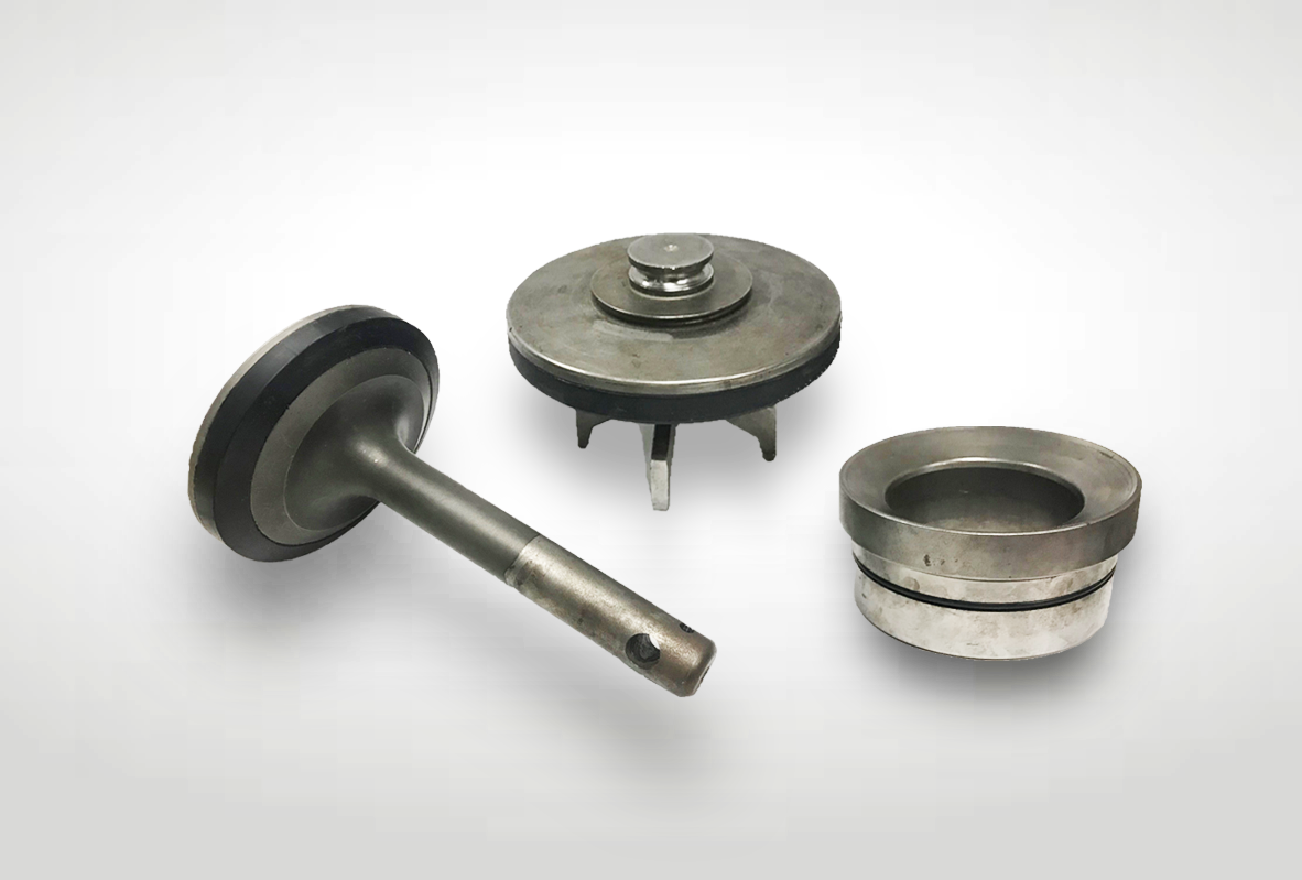
Design innovation has been the driving force for Weir Novatech and its rigid full open valve and seat. Novatech offers valves and seats for all major well service and mud pump applications including work-over, cementing, acidizing, fracturing and drilling. Weir Novatech valves and seats are manufactured by combining the advantages of forged steel to assure impact strength and precision casting to maximize flow and minimize fluid turbulence. All Weir Novatech valves and seats are manufactured to rigid quality control standards. Weir Novatech is the leader in full open valve and seat technology, providing the first drilling valve and seat in the industry rated for continuous service at 7500 PSI. Available in API 4, 5, 6, 7 and 8 sizes, plus seats for all OEM tapers. Weir Novatech manufacturers the strongest and most reliable valve and seat in the industry.

The frac pump valves and seats are also called valve and seat assembly. There are valve body, valve insert, valve seat, and O-ring, these four parts consist of the frac pump valves and seats, which are very critical vulnerable parts in fracturing pumps. In higher pressure frac pumps, the mating surface of the valve body and valve seat is generally a conical surface. Frac valves and seats are the no. 1 expendables cost. 8620H or 20CrMo can be used for forged frac valves and seats. Both the valve body and valve seat would be carburized or nitrided to enhance their impact resistance and wear resistance. Polyurethane is often used as the raw material for the valve insert. Compared with rubber, polyurethane has better strength and elasticity.
This FAQ lists some questions about frac pump valves and seats for you. These FAQs shall be able to answer some queries related to the well-service pump valves and seats.
Novatech is a valves and seats manufacturer in the US. Its first welding valves were supplied nationally in 1982. As one of the oldest and strongest frac valves and seat manufacturers, a wide variety of valves & seats manufactured by Novatech are used throughout the world.
Novatech’s four streamlined guide legs full open seat valve have greatly increased the reliability and performance. The web-type valve seat was achieved to maximize the metal-to-metal bearing area. However, the loads applied to the seat webs are not uniform, the flow is not limited because of the Novatech four streamlined guide legs and the metal-to-metal bearing area is regained, the Novatech full open valve seat assembly can keep the impact loads uniformly transmitted to the frac pump fluid end. One-piece valve bodies, the insert retention groove acts as a circular channel beam to add superior rigidity to the valve body.
TianyuMfg provides 100% interchangeable frac valves and seats with Novatech’s. Our valves and seats are manufactured by high-quality alloy steel and which is forged integrally. The developed high, medium, and low-end products suit different working conditions for you to choose, including work-over, acidizing, cementing, fracturing, and drilling.
The plungers size defines the frac pump fluid end size. The frac pump valves and seats change with the plunger size but not all the same, some fluid ends of different plunger specs also share the valves and seats of the same size. You can find the following charts which list the general sizes of frac pump valves and seats:
Tianyu Mfg. Provides various kinds of frac pump valves and seats. Contact TianyuMfg sales engineer to get the most appropriate valves and seats for your pumps.
The frac pump valve section is divided into the suction valve and discharge valve on the drawings. However, in order to make the disassemble and maintenance of the frac pump valve convenient, the suction and the discharge valve body adopt the exactly same design. The suction valve body is located at the lower part of the frac pump fluid end, and the discharge valve is located at the upper part of the frac pump fluid end.
By the reciprocating movement of the plunger, the suction valve and the discharge valve continuously open and close. When the suction valve keeps opening and the discharge valve closing, the liquid pours into the frac pump fluid end cylinder cavity through the suction manifold and the suction valve to complete the liquid suction. When the discharge valve keeps opening and the suction valve closing, the liquid discharge from the frac pump fluid end cylinder cavity through the discharge valve land the discharge pipe to complete the liquid discharge.
In the operation of the frac pump, the frac pump valves and seats are constantly opening and closing. Therefore, the closing speed of the frac pump valves and seats require special attention. There is a certain impact that emerges due to kinetic energy changing at the closing moment of the frac pump valves. The impact strength is related to the mass and closing speed of the frac pump valves and seats. The greater the mass and speed are, the greater the impact strength will be. The shock is the main factor that triggers the frac pump valves and seats to be damaged. It makes the allowable closing speed is a key parameter of the frac pump valves and seats design.
You need to prepare sufficient spare frac pump valves and seats parts. The quality of frac pump valves and seats directly affect the performance of the frac pump fluid end. Tianyu Mfg. serves low cost and superior performance frac pump valves and seats. As the valve body is manufactured as a one-piece, which increased resistance to abrasion and extrusion, also minimizes insert movement, leakage, and separation from the valve.
When the insert is almost damaged across the surface and caused the valve to leak, replace the insert. After replacing, no leakage keeps them working. Leakage till happened, replace the frac pump valve body. The leakage caused by the insert failure would arise the valve washout and fail easily tend to rapid erosion.
Increasing the metal-to-metal bearing area between the valve and seat is the only method to lengthen the life span of the frac pump valves and seats. The bigger this area, the bigger the area to absorb the high-impact energy from valve closing. We recommend the following tips for you as a reference.

Weir provides the oil and gas industry with the best in full open valve and seat technology and manufactures a wide variety of valves and seats for workover pumps, high pressure well service fracturing pumps, cementing pumps and mud pumps through its Novatech™ pressure pumping equipment line.
Novatech leads the industry in full open valve and seat technology and manufactures valves and seats for workover pumps, high pressure well service fracturing pumps, cementing pumps and mud pumps. Novatech also manufactures caged assemblies for almost all well service pumps and applications, including workover, cementing, acidizing and fracking. Novatech developed the first valve and seat in the industry rated for continuous service at 7,500 psi. Products are 100% made in U.S.A.
Reasontek carry Weir/Novatech products for oilfield applications including valves, seats, inserts replacement of pump maintenance. Please check the catalogue below and let us know your request.

Novatech is now part of Weir Oil & Gas a leader in the design, manufacture and service of pumps and ancillary equipment for upstream and downstream markets. Weir Novatech is an industry leader in full open valve and seat technology and manufactures a wide variety of valves and seats for workover pumps, high pressure well service fracturing pumps, cementing pumps and mud pumps.
FLUID END EXPENDABLE PUMP PARTSBaker SPD62DOUBLE ANGLE O-RING VALVEThe Double Angle O-ring Valve is made with a tough one-piece body to run more hours between change outs. It"s made withcarburized premium alloy steel to resist wear, provide a positive seal, and help protect against wash out or damage to the pump.FEATURESSpecified for all drilling operations up to and exceeding 5,000 psi Maximum operating temperature is 170F Patented polyurethane insert is noted for its Double Angle 55seal contact surface, which maintains cylinder priming during pump shutdown Sizes fit most mud pumps Shelf life of polyurethane insert is maximum of 5 years Body is a one-piece design, configured to give maximum containment of the insert with minimum use of materialDOUBLE ANGLE O-RING BLUE STREAK HIGH TEMPERATURE VALVEThe High Temperature Double Angle O-ring Valve body is a one-piece design, configured to give maximum containment of the insert with minimum use of material. The valve and insert configuration has been operated at pressures up to and exceeding 5,000 psi. FEATURESMaximum operating temperature is 200FShelf life of polyurethane insert is maximum of 5 yearsSTANDARD PLATE TYPE VALVEThe Standard Plate Type Valve is extremely durable to its premium forged alloy steel body and its unique design. It has been proven by more than 50 years of oilfield service. To prevent dry pistons and liners at startup, the valve features a patented double angle polyurethane insert that maintains cylinder priming during pump shut-down. The precise control of insert pre-load is accomplished with a flat ground insert retaining plate and split retainers. The insert can be replaced in the field with minimum down time. This valve is designed to fit pumps in the oilfield and is used with Baker SPD seats. FEATURESSpecified for all drilling operation up to and exceeding3,500 psiMaximum temperature rating for the standard polyurethane insert is 170FMaximum temperature rating for the Buna-N rubber insert is225FAvailable with Buna-N rubber or polyurethane insertsShelf life of polyurethane insert is maximum of 5 yearsShelf life of Buna-N rubber is maximum of 10 yearsValves with rubber lipless inserts are rated for pressure up to2,500 psiNote: Baker SPD Double Angle O-ring and Standard Plate Type Valves do not interchange with any other manufacturer.Double Angle O-ring Seat, Spring, and ValveDouble Angle O-ring Seat, Spring, and High Temperature ValveStandard Plate Type Seat, Spring, and ValveVALVES AND SEATS 2007 SPD. All rights reserved.4302 Prot, San Antonio, Texas 78219, Tel 1-800-688-5650 or (210)-304-5650, Fax (210) 304-5641Triplex Pump PistonsSPD provides a wide variety of pistons for mud pump appli-cations, including bonded, urethane, rubber, and replaceable rubber or urethane inserts.SPDs bonded urethane pistons are designed for resistance to extrusions and abrasions. With water cooling, these pis-tons will provide optimum performance in oil base mud and high drilling pressures. Bonded urethane pistons are rated for drilling opera-tions up to and exceeding 5,000 psi Urethane pistons provide extended service life under high pressure The Blue Streak
High Temperature Bonded Urethane Triplex PistonTriplex BondedRubber PistonFor more information on liners and other products, please visit us at www.ForumSPD.com or email sales@ForumSPD.com.Zirconia Ceramic Liners HP Design with shoulder on hull to prevent sleeve slippage SPD ID tolerances is +.010/-.000 - Industry allowance is +.015/-.000 Surface nish 4 8 RMS - Chrome sleeved liner nish 16 20 RMS Expected run life exceeding 10,000 hours Hardness: HV 0.3 kg/mm - 1100/1200 (92 94 Rc) (Chrome sleeved liners are 60 64 Rc) Ceramic liners do not create ID ridges which are common in high chrome liners. ID ridges are a cause of piston failures. Ceramic liners improve piston run life. Ceramic liners are pressure rated to pump performance by piston size. Liners are available in sizes 4-1/2 to 7. Liners are available for popular pumps: EMSCO: FC-2200, FB-1300/1600, F-800/1000 Gardner Denver: PX-11, PZ-10/11, PZ-8/9 National: 14-P-200/220, 12-P-160, 10-P-130 Oilwell: A1400/1700PT Wirth: TPK-2200, TPK-1600/2000 Liners for other pump models and liner sizes available upon request.For more information on liners and other products, please visit us at www.ForumSPD.com or email sales@ForumSPD.com. You can also contact us by calling 1-800-688-5650. Zirconia Sleeved Liners for Mud Pumps in Drilling Applications Basic description of Zirconium Oxide/Zirconia: Zirconia engineered ceramic parts can be formed by single axis pressing, isostatic pressing, injection molding, slip casting, or extrusion. Parts can "green machined" to near net size before firing and then "hard" ground using diamond tooling to tolerances less than 0.0002" (0.005 mm). Special grades of zirconia can be enhanced with additives to create a multiphase material and also metallized creating an option to be brazed to metal parts. Applications: Although there are a number of uses for Zirconia, the application of a Zirconia sleeve for a mud pump liner is gaining increasing attention. Although other materials have been used for mud pump liners such as high chromed sleeves and Aluminum Oxide sleeves, Zirconia is gaining favor in this application. A Zirconia sleeve is much harder than a chrome sleeve and therefore offers longer life. Although Ziconia is softer than Alumina, it is not as brittle and therefore will survive low impact shock loading and moderately rough handling. The run life of these two ceramic materials is very close, however because of the careful handling required by Alumina sleeved liners to prevent cracking damage, Zirconia liners are preferred. The Multiphase compound process results in a much smaller grain size which is one of the factors to improve wear life. Properties of Zirconia PSZ MS Grade and Zirconia Multiphase Properties Units Test Temp. Zirconia MS Grade Zirconia Multiphase Density G/cm3 20qC 5.74 5.6-5.7 Flexural Strength MPa 20qC 725 650-800 Tensile Strength MPa 20qC 450 - Weibull Modulus m 20qC >30 >25 Compressive Strength MPa 20qC 1990 1900 Modulus of Elasticity GPa 20qC 205 210-220 Poissons Ratio 20qC 0.31 0.31 Hardness HV0.3 kg/mm2 20qC 1120 1100-1200 Fracture Toughness MPam 20qC 8-12 11-14 Average Grain Size Pm - 40 0.35 - 2 Thermal Conductivity W/m-K 20qC 3.08 2.5 Thermal Expansion Coefficient X 10-6/C 20-400qC 10.2 9.1 Specific Heat J/g-K 20qC 0.47 0.40 Operational Characteristics: Standard chrome sleeve liners wear at a rate of about .007" to .010" on the diameter per 100 hours under normal conditions. When a liner reaches about .070" over nominal diameter the engagement with the piston reduces to a point that blow by begins, resulting in piston failure. The liner wears like a barrel on the ID resulting in the maximum wear at the center of the stroke. The ends of the liner will be at the original nominal diameter. Ceramic sleeve liner will wear in the same way as chrome liners but at a rate of about .001" or less per 100 hours. This rate of wear will result in potential life of 10,000 or more hours. Of course there are a number of variables which would shorten or even lengthen the run time. Recent tests conducted with KCA Duetag and Nabors Drilling have confirmed that wear of only .020 or less have occurred in 4000 hours. Projection of this wear rate would indicate a life of 14,000 hours or more. Urethane pistons are recommended for use with ceramic liners. Piston life in a ceramic liner is variable. The initial piston normally will only run about 200 hours or less. During the initial run the piston further smoothes the liner ID. Subsequent pistons have been known to run much longer up to 500 or 600 hours. However, as the liner becomes worn, the piston lip will begin to loose interference with the liner ID, reducing run life. The above noted run times are dependent on operating conditions. Typical conditions are pressure to 3800 psi, stroke rate to 90 spm, temperature below 170 degrees F, clean mud with weights of 11 to 14 lbs. and a high volume water flush to the back of the piston is required. Higher pressures, stroke rates and temperatures will increase the wear rate.

. OIL WELL MUD PUMP VALVE Filed Oct. 23, 1952 ATTORNEY- United States Patent 2,745,631 OIL W"ELL MUD PUMP VALVE Roy K. Shellman, Compton, Califi, :assignor to Mac- Clatchie Manufacturing Co., Compton, Cali, 2 corporation of California Application October 23, 1952,"Serial"No. 316,347 1 Claim. (Cl. 251-175) This invention relates to improved valve structures particularly adapted" certain respects for use as fluid inlet and outlet check valves in high pressure pumps, as for instance in oil well mud pumps.
The operating pressures of an oil well mud pump are usually extremely high, with the result that the inlet and outlet valves of the pump are opened and closed rapidly and with very great force. Consequently, unless the valves are of a special wear resistant construction, their repeated closures tend to quickly damage the engaging surfaces of the valve and its seat, andsoon render the valve ineffective to close off "fluid"flow. For this reason, it has heretofore been proposed to provide the movable valve element and its seat with interengageable stop shoulders (in addition to the main valve surfaces), which act to limit closure of the valve element and thus prevent damage to the sealing surfaces. These stop shoulders have heretofore been formed at an inner side of the valve element inwardly beyond the seat surface in the direction of valve closing movement. In order that the valve seat may be of a construction to prevent a stop shoulder at that location, the seat has generally been formed as a forging, usually having a valve guide portion as well as the stop shoulder at the inner side of the valve structure.
The oil well mud pump .check valve "10 shown in Figs. 1 and 2 includes a seat section 11 and .a movable"valve unit 13. The seat section 11"i s annular and typically formed of a short length of metal tubing. At its inner side, seat 11 has an annular inclined upwardly facing seat surface 14 against whichan annular inclined downwardly facing surface 15 of deformable element 16 of the valve unit 13 seats in closed condition of the"valve. At its upper end, seat .11 has an annularsurface or"shoulder "17, which preferably extends directly transversely .of the valve axis, and is engageable"by transverse shou"lder"25 at the underside of flange "26 of valve unit "13"to liriiitLits downward or closing movement. The verticallymovable valve unit 13 includes a vertically extending stem 27, which carries the above mentioned transverse stopfflange 26. The upper end. of stem .27 may be guided -for the desired vertical"movement by reception within boref2 8yin a guide member "29, with the valve unit being yieldingly urged downwardly to closed condition by spring 30.
Beneath flange 26, valve stem 27 carries a resiliently deformable annular seat engaging element 16, which may include a main rubber portion 31 and fabric or plastic reinforcing 32. The inclined seat engaging surface 15 of deformable element 16 is preferably disposed at a slightly greater angle to the valve axis than is the seat surface 14, to assure the formation of a most effective fluid seal between the parts. Element 16 may be backed at its upper side against the central portion of flange 26, which is in turn backed against an integral flange 38 on stem 27. The outer portion of valve element 16 is axially spaced from flange 26 at 137, to provide an annular space into which fluid may flow through circularly spaced openings 35 in the flange to urge element 16 downwardly against its seat. As will be understood, the force of such fluid acts in the closed condition of the valve to urge the valve element tightly against its seat 14.
In use, the valve of Figs. 1 and 2 is normally urged by spring 30 to its closed position of Fig. 2, in which surfaces 14 and 15 form a tight fluid seal. The downward closing movement of movable unit 13 is limited in the Fig. 1 position by engagement of stop shoulders 24 and25 on seat section 11 and flange 26. When the fluid pressure beneath the movable valve unit 13 reaches a predetermined value, unit 13 moves upwardly, to pass fluid upwardly past seat surface 14 and flange 26. When the pressure at the underside of the valve subsequently decreases, spring 30 and the fluid pressure at the upper side of the valve return unit 13 downwardly to closed By virtue of the interengagement of stop 25, the closing movement of the valve is limited, regardless of how great the closing force may be, without damage to seat surface 14 or deformable element 16. It also will be seen that the inward axial spacing of the sealing surface 15 of the element 16 from the stop surface 25 on the flange 26 precludes any pinching off of the element 16 as the surface 25 slams against the stop surface 17. Furthermore, because of such spacing, the radially inwardly directed fan-shaped jet squeezed from between the surfaces 25 and 17 as the valve closes, does not detrimentally impinge on the sealing surface 15. In order that the limitation of valve movement may be as eifective as possible, and to assure a minimum wear on the parts, seat section 11 and flange 26 are preferably formed of a suitable very tough and hard steel or other metal.


 8613371530291