
oil base mud pump free sample

Created specifically for drilling equipment inspectors and others in the oil and gas industry, the Oil Rig Mud Pump Inspection app allows you to easily document the status and safety of your oil rigs using just a mobile device. Quickly resolve any damage or needed maintenance with photos and GPS locations and sync to the cloud for easy access. The app is completely customizable to fit your inspection needs and works even without an internet signal.Try Template

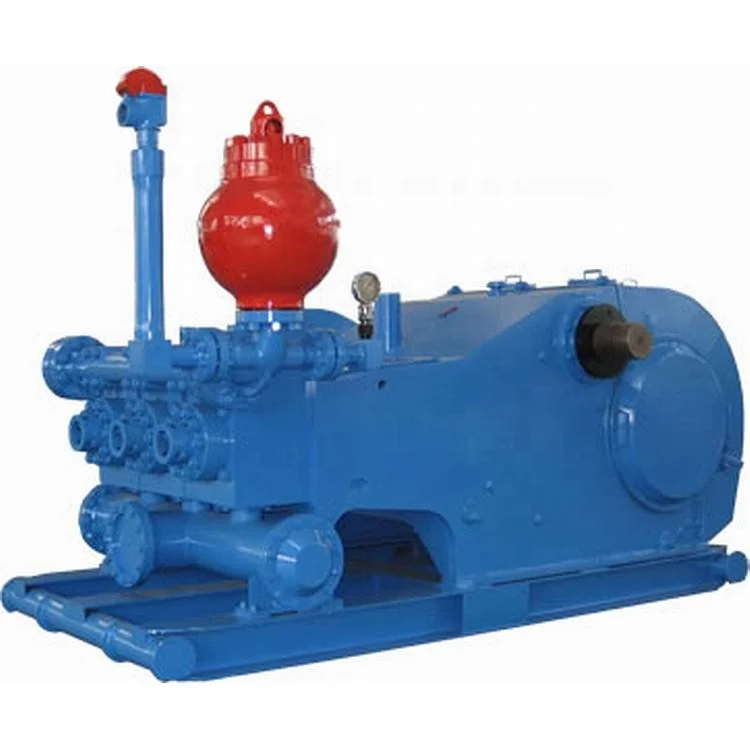
The 2,200-hp mud pump for offshore applications is a single-acting reciprocating triplex mud pump designed for high fluid flow rates, even at low operating speeds, and with a long stroke design. These features reduce the number of load reversals in critical components and increase the life of fluid end parts.
The pump’s critical components are strategically placed to make maintenance and inspection far easier and safer. The two-piece, quick-release piston rod lets you remove the piston without disturbing the liner, minimizing downtime when you’re replacing fluid parts.

I’ve run into several instances of insufficient suction stabilization on rigs where a “standpipe” is installed off the suction manifold. The thought behind this design was to create a gas-over-fluid column for the reciprocating pump and eliminate cavitation.
When the standpipe is installed on the suction manifold’s deadhead side, there’s little opportunity to get fluid into all the cylinders to prevent cavitation. Also, the reciprocating pump and charge pump are not isolated.
The suction stabilizer’s compressible feature is designed to absorb the negative energies and promote smooth fluid flow. As a result, pump isolation is achieved between the charge pump and the reciprocating pump.
The isolation eliminates pump chatter, and because the reciprocating pump’s negative energies never reach the charge pump, the pump’s expendable life is extended.
Investing in suction stabilizers will ensure your pumps operate consistently and efficiently. They can also prevent most challenges related to pressure surges or pulsations in the most difficult piping environments.

Effective removal of drilling muds and related solids from cased wellbores prior to adding solids-free brine during the completion process is a critical point for well operations. Efficient displacement of the drilling fluid itself and any particles attached to the casing wall is essential to maintain completion brine and mud integrity, as well as to reduce filtration costs and rig time. A failed displacement can lead to completion complications (such as stuck packers) or potential formation damage due to loss of drilling mud solids to the formation. Modern drilling fluids have progressed to meet more challenging, drilling applications, as well as stricter health, safety, and environmental standards. Many of these advanced drilling fluid systems contain new emulsifier and additive packages, which have increased the difficulty in removing drilling mud from the cased wellbore with traditional displacement spacer surfactant systems.
This paper discusses a laboratory test used in the mud removal studies with an emulsion-based displacement spacer. It also details the efficiency of an emulsion-based displacement spacer in removing actual field compositions of synthetic (SB) and oil-based (OB) drilling muds. Mud parameters such as density, base-oil type and rheologies are detailed to characterize the type of mud and the difficulty in displacing the mud system from the wellbore casing. Also, the environmental advantages of this low-toxicity, non-polluting emulsion-based displacement system are outlined.
Field case histories detail the use of this emulsion-based spacer in the North Sea to displace a wide range of SB/OB drilling mud systems. This paper also outlines how this product optimized removal of SB/OB drilling mud systems, decreased rig operation time, and reduced the volume of mud solid slop due to efficient phase separation and emulsion breaking of the drilling mud systems.

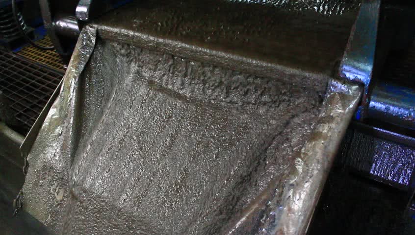
Drilling mud is most commonly used in the process of drilling boreholes for a variety of reasons such as oil and gas extraction as well as core sampling. The mud plays an important role in the drilling process by serving numerous functions. The main function it is utilized for is as a lubricating agent. A large amount of friction is generated as drilling occurs which has the potential to damage the drill or the formation being drilled. The mud aids in the decrease in friction as well as lowering the heat of the drilling. It also acts a carrier for the drilled material so it becomes suspended in the mud and carried to the surface.
Using a Moyno progressive cavity pump, the drilling mud with suspended material can be pumped through a process to remove the solids and reuse the cleaned mud for further drilling.

[0001] Aspects relate to the field of oil well services. More specifically, aspects relate to oil based drilling mud filtrate contamination monitoring.
[0002] Oil based drilling mud (OBM) filtrate contamination monitoring (OCM) is one of the biggest challenges in downhole fluid analysis. Conventional systems and algorithms are not capable of providing adequate results for OBM contamination monitoring, particularly with focused sampling interface modules. Accurate and quantitative OBM contamination measurement is a key enabler of quality sampling and quality downhole fluid analysis (DFA). New algorithms are highly demanded for this purpose.
[0003] Conventional systems do not disclose or suggest any capability that gas/oil ratios may be used in oil based mud filtrate contamination monitoring quantitatively. Previous attempts at developing a relationship have failed as conventional fluid analyzers display a negative gas/oil ratio in Oil Based mud filtrate. This limits its use in quantifying Oil Based mud contamination. Extrapolating contamination free gas/oil ratios determined by asymptotic fitting methods does not work, especially for focused probes and/or new developed probes and packers.
[0004] In one example embodiment, a method for monitoring OBM contamination, is disclosed, comprising analytically dividing a fluid stream into two parts, determining a gas/oil ratio for a native (or OBM filtrate contamination free) fluid, determining an apparent gas/oil ratio for the native fluid, and determining on a volume fraction, an oil based mud filtrate contamination level based upon the gas/oil ratio for the native fluid and the apparent gas/oil ratio for the native fluid.
[0005] A novel procedure is provided for oil based mud filtrate contamination monitoring and determination of oil based mud filtrate contamination level. Based on the definition of gas/oil ratio, a simple formula is developed to relate oil based mud filtrate contamination level in volume fraction in stock tank oil (STO) to apparent gas/oil ratio which is measured by downhole fluid analysis. The end point for native (contamination free) oil can be determined in different ways using multiple sensors in downhole fluid analysis. Additionally, density itself can be used for oil based mud filtrate contamination monitoring using a mixing rule. When combining the oil based mud contamination level results from gas/oil ratio, density and pressure gradients with those from optical density calculations, confidence is significantly gained in particular when all the results are close. In addition, the oil based mud filtrate contamination monitoring algorithms can be applied not only for individual guard and sampling flowlines but also for combined guard and sampling flowlines. These formulas and algorithms can be used for oil based mud filtrate contamination monitoring in real time and postjob analysis.
[0017] Through aspects described herein, it is now possible to use the value of gas/oil ratio for oil based mud filtrate contamination monitoring. The oil based mud filtrate contamination monitoring formula is derived from the definition of gas/oil ratio and oil based mud filtrate contamination level in volume fraction on the basis of dead oil (stock tank oil, STO). Confidence is significantly gained using gas/oil ratio as oil based mud filtrate contamination monitoring due to this theoretical base.
[0018] Additionally, the new generation of downhole fluid analysis, like in situ fluid analyzer, avoids negative gas/oil ratio (normalizing GOR to zero for dead oil) in the algorithm and the assumption of zero gas/oil ratio for pure oil based mud filtrate is valid.
[0019] Contamination free GORo for native oil can be determined from different methods, which can gain confidence for the analysis. For example, (1 ) density derived from pressure gradients and GOR0 from a linear relationship between density and gas/oil ratio measured by downhole fluid analysis; (2) GORo from the asymptotic fitting method is also used for reference. The linear relationship between density and gas/oil ratio is confirmed by laboratory and field data.
[0021] Oil/gas ratio can be measured by downhole fluid analysis based on downhole optical spectra using optical densities at multiple hydrocarbon channels, referred to as apparent gas/oil ratio. In-field practice, apparent gas/oil ratio was used to guide downhole reservoir fluid sampling along with other sensor measurements downhole during cleanup, especially for focused probes and new developed probes and packers. Once apparent gas/oil ratio reaches a stable value with time or/and pumpout volume, one is able to start sampling. Gas/oil ratio can be used as well to determine oil based mud filtrate contamination levels and then for oil based mud filtrate contamination monitoring during cleanup.
[0022] It is reasonably assumed that pure oil based mud filtrate has no gas/oil ratio (no gas dissolved in pure oil based mud filtrate) and cannot be vaporized into the gas phase at a single stage flash at standard conditions (the flash process reaches equilibrium). Based on the definition of gas/oil ratio, a simple formula is derived for the first time to relate oil based mud filtrate contamination level in volume fraction in stock tank oil (STO) to gas/oil ratio. Therefore, one endpoint gas/oil ratio for pure oil based mud filtrate is zero, and the other endpoint gas/oil ratio for native oil can be determined in different ways using multiple sensors in downhole fluid analysis.
[0023] Using gas/oil ratio and multiple sensors in downhole fluid analysis as oil based mud filtrate contamination monitoring has the following advantages:
2. Large gas/oil ratio contrast (e.g. 0 scf/bbl for oil based mud filtrate and 20 - 50000 scf/bbl from heavy oil to gas condensate) between pure oil based mud filtrate and native oil.
3. Linear (near linear) relationship between gas/oil ratio and density confirmed from laboratory and field data, which allows to extrapolate gas/oil ratio to
native oil based on density from pressure gradients and other methods, which also allows to extrapolate density of pure oil based mud filtrate by setting gas/oil rato to zero.
4. Engineers may estimate endpoint gas/oil ratio for native oil in a sense from information of nearby wells, nearby downhole fluid analysis stations and the like.
6. If the result becomes close by integrating multiple sensor oil based mud filtrate contamination algorithms such as gas/oil ratio, density and optical density, confidence about the answer is significantly gained.
7. Gas/oil ratio cannot be used for oil based mud filtrate contamination monitoring in previous generations of downhole fluid analysis such as optical fluid analyzer, live fluid analyzer and advanced fluid analyzer but a new generation of downhole fluid analysis such as in situ fluid analyzer because the gas/oil ratio algorithm in optical fluid analyzer, live fluid analyzer and advanced fluid analyzer does not normalize gas/oil ratio to zero (negative gas/oil ratio occurs for low gas/oil ratio fluids) at the low end.
[0024] For a native live fluid, the single stage flash gas/oil ratio is defined as the ratio of the volume of the flashed gas that comes out of the live fluid solution, to the volume of the flashed oil (also referred to as stock tank oil, STO) at standard conditions (typically 60° F and 14.7 psia)
where GORo, Vgas and V0no are the gas/oil ratio of the native fluid, the flashed gas volume and the volume of flashed native (oil based mud filtrate contamination free) STO at standard conditions respectively.
[0025] The contaminated fluid is divided into two components: the pure oil based mud filtrate and the native fluid. If the reservoir fluid is contaminated by oil based mud filtrate and it is assumed that the oil based mud filtrate exists only in the flashed liquid (oil) phase (i.e., the oil based mud filtrate has no gas/oil ratio), then gas/oil ratio of the contaminated fluid can be expressed as in equation two (2):
v (2) oil 0 obm where the total volume of STO (VSTO) is the summation of the oil based mud filtrate volume {V0bm) and native STO volume {V0no) at standard conditions. Divided both numerator and denominator by V0//o on the right-hand side, Equation (2) can be rearranged as:
G R0 {V∞w + Vobm) {Vml0 + Vobm y where vobmSTo is the oil based mud filtrate contamination level in volume fraction in stock tank oil (STO) at standard conditions.
[0026] Equation (5) can be used for downhole oil based mud filtrate contamination monitoring in real time. Apparent gas/oil ratio can be measured by downhole fluid analysis at a series of time during cleanup. The endpoint, GOR0 (gas/oil ratio for the native fluid), can be determined by the following different ways. Then the most suitable gas/oil ratio is selected for GORo.
[0027] Gas/oil ratio is typically in a linear relation with live fluid density. To test the relationship, gas condensate, black oil and heavy oil have been mixed with three types of oil based mud filtrates (esters, mineral oil and olefins) at 10wt%, 25wt% and 40wt% oil based mud filtrate based on STO, respectively, and then the gas/ratio ratio and density are measured for all the mixtures. The results are shown in FIGS. 1 , 2 and 3. The results clearly show that the relation between density and gas/oil ratio is linear.
[0028] The real time in situ fluid analyzer data also show the linear relationship between gas/oil ratio and live density as illustrated in FIG. 4. It can be seen that the higher density data in the low gas/oil ratio range are off the trend because the fluids may contain some solids and/or be compressed due to a pressure increase at the beginning of the cleanup process.
[0029] Because downhole fluid analysis measures apparent gas/oil ratio and density during cleanup, a linear relation can be determined from the cleanup data by selecting a suitable time interval. Pretest pressure (pressure gradient) data can be used to determine density of the contamination free fluid - density endpoint for the native fluid. Thus, the linear relation between gas/oil ratio and density can be extrapolated in terms of the density obtained from the pressure gradient. As a result, the endpoint GORo can be determined. Once GOR0 is obtained, oil based mud filtrate contamination level can be estimated by Equation (5) at a series of time (pumpout volume) based on apparent gas/oil ratio measured by downhole fluid analysis. On the other hand, this linear relation
P = Po - V (6) where p and \ are the density and pumpout volume (can be replaced by time t) measured by downhole fluid analysis; p0, y?and γ are three adjustable parameters. Once good density data regression is obtained, density (p0) for the native fluid can be extrapolated by assuming that the pumpout volume (time) approaches infinity. Then GORo for the native fluid can be determined from the linear relationship between gas/oil ratio and density mentioned previously. For the focused flow, V can be replaced by the volume in the sample line instead of total volume (summation of sample and guard line volumes).
[0032] When gas/oil ratio becomes unchanged (derivative of gas/oil ratio with respect to pumpout volume (time) is zero) even changing flowrate in guard or sampling flowline, that gas/oil ratio is taken as GORo. This method may be used in field practice for focused sampling and new developed probes and packers.
GORo, ? and γ are the three regression parameters and they are determined by fitting the GOR and pumpout volume (time) data during cleanup. Setting V to infinity, GORo is assumed to be the GOR for the native fluid.
or ln(f). a straight line can be observed. The slope is γ and the interception is \n{ /GORo). Because GOR0 is assumed, β can be determined. GOR0 is then updated; updating β and is followed. The process may be repeated and the most suitable GOR0 may be found for the best fit for the graph as well as other objectives. An example is shown in FIGS. 5 and 6 and the data come from in situ fluid analyzer measurements. FIG. 5 illustrates gas/oil ratio fitting results using Equation (7). FIG. 6 gives the
[0035] All these methods can be used to obtain GORo for the native fluid. Finally, a most suitable GORo is selected for oil based mud filtrate contamination level estimation.
[0036] Once GORo is obtained and the pumpout flowrate is known, the time required for sampling to reach a certain oil based mud level can be calculated by:
(1 1 ) where At, AV, and Qpump are the time required to reach a specified OBM level, the pumpout volume required to reach the specified OBM level, and the pumpout volume flowrate (assuming to be a constant).
[0037] Again, the contaminated fluid is divided into two components: the pure oil based mud and the native fluid. It is assumed that the mixing of the oil based mud filtrate and native fluid is ideal, i.e., producing no excess volume:
where V770" and x are the molar volume and mole fraction. Subscripts obm and 0 represent the pure oil based mud filtrate and native fluid. The molar volume and mole fraction can be changed into density (p) and oil based mud filtrate volume fraction (v0bm) at downhole conditions by:
[0039] In Equation (14) and Equation 15, two endpoints - densities of pure oil based mud {pobm) and native fluid (/¾) should be known. It should be noted that density contrast between the pure oil based mud filtrate and native fluid should be large enough in order to use Equation (14) and (5) for oil based mud filtrate contamination monitoring.
a) Measure the density of pure oil based mud filtrate if pure oil based mud filtrate (or base oil) is available before logging at different temperatures and pressures covering entire reservoir conditions.
b) According to the linear relationship between gas/oil ratio and density mentioned previously, setting gas/oil ratio to zero, the density obtained is the density of the pure oil based mud filtrate.
c) At the beginning of clearup, 100 % oil based mud filtrate may be pumped in flowline. The downhole fluid analysis measured density at the beginning of clearup may be considered to be the density of pure oil based mud filtrate.
e) During cleanup, live fluid density can also be fitted by Equation (6). Once good density data regression is obtained, density (p0) for the native fluid can be extrapolated when the pumpout volume (time) approaches infinity.
STOStd 1^1 Stc where wobmSTo, psTostd, Mgas, R, Pstd and Tstd are the oil based mud filtrate contamination level in weight fraction based on STO at standard conditions, the STO density at standard conditions, the molecular weight of flashed gas at standard conditions, the universal gas constant, the standard pressure (typically 14.7 psia) and standard temperature (typically 60° F), respectively. PsTostd and Mgas can be estimated by the method proposed in United States Patent 7,920,970. FIG. 7 shows the conversion factor as a function of gas/oil ratio, Mgas and psrostd- For high gas/oil ratio fluids, oil based mud weight fraction based on STO is quite different from that at downhole conditions.
[0045] If it is assumed that the density ratio of oil based mud filtrate to fluid at reservoir and standard conditions (i.e., the isothermal compressibility of both oil based mud filtrate and fluid) are approximately identical, the same conversion factor can be used for both oil based mud weight and volume fractions.
[0046] The existing oil based mud filtrate contamination monitoring methods such as the methane and color channel oil based mud filtrate contamination algorithms, multichannel oil based mud filtrate contamination algorithms can be used as well.
The tool string is shown in FIG. 8. The PQ, DV-Rod and in situ fluid analysis were used. Only comingling up flow was performed. Gas/oil ratio and density variations with
pumpout volume are shown in FIG. 9. The gas/oil ratio and density relationship is given in FIG. 10. GOR fitting (FIG. 9) shows GOR0 = 595 scf/bbl for the native oil. The native oil and pure OBM densities are obtained by the linear relation between GOR and density, p0 = 0.762 g/cm3 and p0bm = 0.875 g/cm3. Therefore, the oil based mud filtrate contamination level can be obtained by both gas/oil ratio and density as shown in FIG. 1 1 . They are very close.
Drilling and well control equipment that are not designed for hydrogen sulfide use could suffer a loss of structural integrity following exposure, which could impede their function and operation during an emergency. Hydrogen sulfide is extremely toxic to humans at minute concentrations. At higher concentrations it is flammable, as well as corrosive to metals. A surface breakout of this gas, if not responded to and controlled immediately, can result in injuries and/or fatalities, fire and explosion. Hydrogen sulfide should be anticipated in all areas of the rig where drilling fluid and associated equipment is present. Those areas include the rig floor, substructure, shale shakers, mud cleaners, mud pit room, mud pump room and well test equipment. Being heavier than air, hydrogen sulfide will settle in low-lying and poorly ventilated areas and will dissolve in oil and water present in those areas.
There are several different types of drilling fluids, based on both their composition and use. The three key factors that drive decisions about the type of drilling fluid selected for a specific well are:
Water-based fluids (WBFs) are the most widely used systems, and are considered less expensive than oil-based fluids (OBFs) or synthetic-based fluids (SBFs). The OBFs and SBFs—also known as invert-emulsion systems—have an oil or synthetic base fluid as the continuous(or external) phase, and brine as the internal phase. Invert-emulsion systems have a higher cost per unit than most water-based fluids, so they often are selected when well conditions call for reliable shale inhibition and/or excellent lubricity. Water-based systems and invert-emulsion systems can be formulated to tolerate relatively high downhole temperatures. Pneumatic systems most commonly are implemented in areas where formation pressures are relatively low and the risk of lost circulation or formation damage is relatively high. The use of these systems requires specialized pressure-management equipment to help prevent the development of hazardous conditions when hydrocarbons are encountered.
Water-based fluids (WBFs) are used to drill approximately 80% of all wells.hole-cleaning effectiveness. After surface casing is set and cemented, the operator often continues drilling with a WBF unless well conditions require displacing to an oil- or synthetic-based system.
Simple gel-and-water systems used for tophole drilling are nondispersed, as are many of the advanced polymer systems that contain little or no bentonite. The natural clays that are incorporated into nondispersed systems are managed through dilution, encapsulation, and/or flocculation. A properly designed solids-control system can be used to remove fine solids from the mud system and help maintain drilling efficiency. The low-solids, nondispersed (LSND) polymer systems rely on high- and low-molecular-weight long-chain polymers to provide viscosity and fluid-loss control. Low-colloidal solids are encapsulated and flocculated for more efficient removal at the surface, which in turn decreases dilution requirements. Specially developed high-temperature polymers are available to help overcome gelation issues that might occur on high-pressure, high-temperature (HP/HT) wells.
Dispersed systems are treated with chemical dispersants that are designed to deflocculate clay particles to allow improved rheology control in higher-density muds. Widely used dispersants include lignosulfonates, lignitic additives, and tannins. Dispersed systems typically require additions of caustic soda (NaOH) to maintain a pH level of 10.0 to 11.0. Dispersing a system can increase its tolerance for solids, making it possible to weight up to 20.0 ppg. The commonly used lignosulfonate system relies on relatively inexpensive additives and is familiar to most operator and rig personnel. Additional commonly used dispersed muds include lime and other cationic systems. A solids-laden dispersed system also can decrease the rate of penetration significantly and contribute to hole erosion.
Polymer drilling fluids are used to drill reactive formations where the requirement for shale inihbition is significant. Shale inhibitors frequently used are salts, glycols and amines, all of which are incompatible with the use of bentonite. These systems typically derive their viscosity profile from polymers such as xanthan gum and fluid loss control from starch or cellulose derivatives. Potassium chloride is an inexpensive and highly effective shale inhibitor which is widely used as the base brine for polymer drilling fluids in many parts of the world. Glycol and amine-based inhibitors can be added to further enhance the inhibitive properties of these fluids.
Oil-based fluids (OBFs) in use today are formulated with diesel, mineral oil, or low-toxicity linear olefins and paraffins. The olefins and paraffins are often referred to as "synthetics" although some are derived from distillation of crude oil and some are chemically synthesised from smaller molecules. The electrical stability of the internal brine or water phase is monitored to help ensure that the strength of the emulsion is maintained at or near a predetermined value. The emulsion should be stable enough to incorporate additional water volume if a downhole water flow is encountered.
Barite is used to increase system density, and specially-treated organophilic bentonite is the primary viscosifier in most oil-based systems. The emulsified water phase also contributes to fluid viscosity. Organophilic lignitic, asphaltic and polymeric materials are added to help control HP/HT(High pressure/High temperature) fluid loss. Oil-wetting is essential for ensuring that particulate materials remain in suspension. The surfactants used for oil-wetting also can work as thinners. Oil-based systems usually contain lime to maintain an elevated pH, resist adverse effects of hydrogen sulfide (H2S) and carbon dioxide (CO2) gases, and enhance emulsion stability.
Shale inhibition is one of the key benefits of using an oil-based system. The high-salinity water phase helps to prevent shales from hydrating, swelling, and sloughing into the wellbore. Most conventional oil-based mud (OBM) systems are formulated with calcium chloride brine, which appears to offer the best inhibition properties for most shales.
The ratio of the oil percentage to the water percentage in the liquid phase of an oil-based system is called its oil/water ratio. Oil-based systems generally function well with an oil/water ratio in the range from 65/35 to 95/5, but the most commonly observed range is from 70/30 to 90/10.
The discharge of whole fluid or cuttings generated with OBFs is not permitted in most offshore-drilling areas. All such drilled cuttings and waste fluids are processed, and shipped to shore for disposal. Whereas many land wells continue to be drilled with diesel-based fluids, the development of synthetic-based fluids (SBFs) in the late 1980s provided new options to offshore operators who depend on the drilling performance of oil-based systems to help hold down overall drilling costs but require more environmentally-friendly fluids. In some areas of the world such as the North Sea, even these fluids are prohibited for offshore discharge.
Synthetic-based fluids were developed out of an increasing desire to reduce the environmental impact of offshore drilling operations, but without sacrificing the cost-effectiveness of oil-based systems.
Field data gathered since the early 1990s confirm that SBFs provide exceptional drilling performance, easily equaling that of diesel- and mineral-oil-based fluids.
In many offshore areas, regulations that prohibit the discharge of cuttings drilled with OBFs do not apply to some of the synthetic-based systems. SBFs’ cost per barrel can be higher, but they have proved economical in many offshore applications for the same reasons that traditional OBFs have: fast penetration rates and less mud-related nonproductive time (NPT). SBFs that are formulated with linear alphaolefins (LAO) and isomerized olefins (IO) exhibit the lower kinematic viscosities that are required in response to the increasing importance of viscosity issues as operators move into deeper waters. Early ester-based systems exhibited high kinematic viscosity, a condition that is magnified in the cold temperatures encountered in deepwater risers. However, a shorter-chain-length (C8), low-viscosity ester that was developed in 2000 exhibits viscosity similar to or lower than that of the other base fluids, specifically the heavily used IO systems. Because of their high biodegradability and low toxicity, esters are universally recognized as the best base fluid for environmental performance.
Normally, the high-salinity water phase of an invert-emulsion fluid helps to stabilize reactive shale and prevent swelling. However, drilling fluids that are formulated with diesel- or synthetic-based oil and no water phase are used to drill long shale intervals where the salinity of the formation water is highly variable. By eliminating the water phase, the all-oil drilling fluid can preserve shale stability throughout the interval.
The development of deformable graphitic materials that can continuously seal off fractures under changing pressure conditions has allowed operators to cure some types of losses more consistently. The application of these and similar materials to prevent or slow down the physical destabilisation of the wellbore has proved successful. Hydratable and rapid-set lost-circulation pills also are effective for curing severe and total losses. Some of these fast-acting pills can be mixed and pumped with standard rig equipment, while others require special mixing and pumping equipment.
Most spotting fluids are designed to penetrate and break up the wall cake around the drillstring. A soak period usually is required to achieve results. Spotting fluids typically are formulated with a base fluid and additives that can be incorporated into the active mud system with no adverse effects after the pipe is freed and/or circulation resumes.
Lubricants might contain hydrocarbon-based materials, or can be formulated specifically for use in areas where environmental regulations prohibit the use of an oil-based additive. Tiny glass or polymer beads also can be added to the drilling fluid to increase lubricity. Lubricants are designed to reduce friction in metal-to-metal contact, and to provide lubricity to the drillstring in the open hole, especially in deviated wells, where the drillstring is likely to have continuous contact with the wellbore.
Corrosion causes the majority of drillpipe loss and damages casing, mud pumps, bits, and downhole tools. As downhole temperatures increase, corrosion also increases at a corresponding rate, if the drillstring is not protected by chemical treatment. Abrasive materials in the drilling fluid can accelerate corrosion by scouring away protective films. Corrosion, typically, is caused by one or more factors that include:
A. R. Ismail, A. Kamis, San Boon Engineering; K. S. Foo, University Teknologi Malaysia: Performance of the Mineral Blended Ester Oil-Based Drilling Fluid Systems, 2001-044, http://dx.doi.org/10.2118/2001-044
Mohammad F. Zakaria,SPE, Maen Husein, SPE: Novel Nanoparticle-Based Drilling Fluid with Improved Characteristics, 156992-MS, http://dx.doi.org/10.2118/156992-MS

OBM have a whole lot of advantages over the conventional WBM. This is due to the various desirable rheological properties that oils exhibit. Since the 1930s, it has been recognized that better productivity is achieved by using oil rather than water as the drilling fluid. Since the oil is native to the formation it will not damage the pay zone by filtration to the same extent as would a foreign fluid such as water. We shall outline some of the desirable properties of oil based muds, which include [4]:Shale Stability: OBM are most suited for drilling shaly formations. Since oil is the continuous phase & water is dispersed in it, this case results in non-reactive interactions with shale beds.
Temperature: OBM can be used to drill formations where BHT (Bottom Hole Temperatures) exceed water based mud tolerances. Sometimes up to over 1000 degrees rankine.
Lubricity: OBM produce thin mud cakes, and the friction between the pipe and the well bore is minimized, thus reducing the pipe differential sticking. Especially suitable for highly deviated and horizontal wells.
Ability to drill low pore pressured formations is accomplished, since the mud weight can be maintained at a weight less than that of water (as low as 7.5 ppg).
Corrosion control: Corrosion of pipes is reduced since oil, being the external phase coats the pipe. This is due to the fact that oils are non conductive, thermally stable, and more often, do not permit microbial growth.
The basic kind of oil used in formulating OBM is the diesel oil, which has been in existence for a long time, but over the years, diesel oil based muds have posed various environmental problems.
Water-based muds (WBMs) are usually the mud of choice in most drilling operation carried out in sandstone reservoir, however some unconventional drilling situations such as deeper wells, high temperature/pressure formation, deepwater reservoir, alternative shale-sand reservoir and shale resource reservoir require use of other mud systems such as oil based mud to provide acceptable drilling performance [5-8].
OBM is needed where WBM cannot be used especially in hot environment and salt beds where formation compositions can be dissolved in WBM. OBM have oil as their base and therefore more expensive and require more stringent pollution control measures than WBM.
It is imperative to propagate the use of environmentally friendly and biodegradable sources of oil to formulate our OBM, thereby making it less expensive and environmentally safe and equally carry out the basic functions of the drilling mud such as maintenance of hydrostatic pressure, removal of cuttings, cooling and lubricating the drill string and also to keep newly drilled borehole open until cementing is carried out.
Environmental problems associated with complex drilling fluids in general, and oil-based mud (OBM) in particular, are among the major concerns of world communities. Among others are the problems faced by some host communities in the Niger Delta region of Nigeria. For this reason, the Environmental Protection Agency (EPA) and other regulatory bodies are imposing increasingly stringent regulations to ensure the use of environmentally friendly muds [7-8].
Throughout the 1970s and 1980s, the EPA and other regulatory bodies imposed environmental laws and regulations affecting all aspects of petroleum-related operations from exploration, production and refining to distribution. In particular, there has been increasing pressure on oil and gas industry stakeholders to find environmentally acceptable alternatives to OBMs. This has been reflected in the introduction of new legislation by government agencies in almost every part of the world.
The researches and surveys conducted came up with possibilities of having environmentally friendly oil based mud. Stakeholders in the oil and gas industry have been tasked with the challenge of finding a solution to this problem by formulating optimum drilling fluids and also reduce the handling costs and negative environmental effects of the conventional diesel oil based drilling fluid. An optimum drilling fluid is one which removes the rock cuttings from the bottom of the borehole and carries them to the surface, hold cuttings and weight materials in suspension when circulation is stopped (e.g during shut in), and also maintain pressure. An optimum drilling fluid also does this at minimum handling costs, bearing in mind the HSE (Health, Safety, Environment) policy in mind [6].
In response to the harmful effects of diesel oil on the environment and on the ozone layer (as a result of the emission of greenhouse gases), researches and surveys have gone on in the past two to three decades, and have come up with mud formulations based on the use of plant oils as diesel substitutes. Over the years, plant oils have become increasingly popular in the raw materials market for diesel substitutes. The most popular being: Rapeseed oil, Jatropha oil, Mahua oil, Cottonseed oil, Sesame oil, Soya bean oil, palm oil etc. This brings about the importance of agro allied intervention in the energy industry. Hence, the contribution of non-edible oils such as jatropha oil, canola oil, algae oil, moringa seed oil and Soapnut will be significant as a plant oil source for diesel substitute production.
This chapter describes the formulation of environmental friendly oil based mud (using plant oil such as jatropha oil, algae oil and moringa seed oil) that can carry out the same functions as diesel oil based drilling fluid and equally meet up with the HSE (Health, Safety and Environment) standards. Mud tests have been carried out at standard conditions on each plant oil sample so as to ascertain the rheological properties of the drilling fluid formulations. The conventional diesel oil based mud would serve as control.
Drilling mud is in varying degrees of toxicity. It is difficult and expensive to dispose it in an environmentally friendly manner. Protection of the environment from pollutants has become a serious task. In most countries like Nigeria, the drilling fluids industries have had numerous restrictions placed on some materials they use and the methods of their disposal. Now, at the beginning of the 1990"s, the restrictions are becoming more stringent and restraints are becoming worldwide issues. Products that have been particularly affected by restrictions are oil and oil-based mud. These fluids have been the mud of choice for many environments because of their better qualities. Initially, the toxicity of oil-based fluids was reduced by the replacement of diesel oil with low-aromatic mineral oils. In most countries today, oil-based mud may be used but not discharged in offshore or inland waters. Potential liability, latent cost, and negative publicity associated with an oil-mud spill are economic concerns. Consequently, there is an urgent need for the drilling fluids industry to provide alternatives to oil-based mud.
Four different mud samples were mixed, and the base fluid was varied. The base fluids were algae, moringa, diesel and jathropha oils used in formulating the muds in an oil water ratio of 70:30, where diesel based mud served as the control.

Specifically designed for drilling companies and others in the oil and gas industry, the easy to use drilling rig inspections app makes it easy to log information about the drill rigs, including details about the drill rigs operators, miles logged and well numbers. The inspection form app covers everything from the mud pump areas and mud mixing area to the mud tanks and pits, making it easy to identify areas where preventative maintenance is needed. The drilling rig equipment checklist also covers health and safety issues, including the availability of PPE equipment, emergency response and preparedness processes, and other critical elements of the drilling process and drill press equipment.

There are many different ways to drill a domestic water well. One is what we call the “mud rotary” method. Whether or not this is the desired and/or best method for drilling your well is something more fully explained in this brief summary.
One advantage of drilling with compressed air is that it can tell you when you have encountered groundwater and gives you an indication how much water the borehole is producing. When drilling with water using the mud rotary method, the driller must rely on his interpretation of the borehole cuttings and any changes he can observe in the recirculating fluid. Mud rotary drillers can also use borehole geophysical tools to interpret which zones might be productive enough for your water well.
The mud rotary well drilling method is considered a closed-loop system. That is, the mud is cleaned of its cuttings and then is recirculated back down the borehole. Referring to this drilling method as “mud” is a misnomer, but it is one that has stuck with the industry for many years and most people understand what the term actually means.
The water is carefully mixed with a product that should not be called mud because it is a highly refined and formulated clay product—bentonite. It is added, mixed, and carefully monitored throughout the well drilling process.
The purpose of using a bentonite additive to the water is to form a thin film on the walls of the borehole to seal it and prevent water losses while drilling. This film also helps support the borehole wall from sluffing or caving in because of the hydraulic pressure of the bentonite mixture pressing against it. The objective of the fluid mixture is to carry cuttings from the bottom of the borehole up to the surface, where they drop out or are filtered out of the fluid, so it can be pumped back down the borehole again.
When using the mud rotary method, the driller must have a sump, a tank, or a small pond to hold a few thousand gallons of recirculating fluid. If they can’t dig sumps or small ponds, they must have a mud processing piece of equipment that mechanically screens and removes the sands and gravels from the mixture. This device is called a “shale shaker.”
The driller does not want to pump fine sand through the pump and back down the borehole. To avoid that, the shale shaker uses vibrating screens of various sizes and desanding cones to drop the sand out of the fluid as it flows through the shaker—so that the fluid can be used again.
Some drillers use compressed air to blow off the well, starting at the first screened interval and slowly working their way to the bottom—blowing off all the water standing above the drill pipe and allowing it to recover, and repeating this until the water blown from the well is free of sand and relatively clean. If after repeated cycles of airlift pumping and recovery the driller cannot find any sand in the water, it is time to install a well development pump.
Additional development of the well can be done with a development pump that may be of a higher capacity than what the final installation pump will be. Just as with cycles of airlift pumping of the well, the development pump will be cycled at different flow rates until the maximum capacity of the well can be determined. If the development pump can be operated briefly at a flow rate 50% greater than the permanent pump, the well should not pump sand.
Mud rotary well drillers for decades have found ways to make this particular system work to drill and construct domestic water wells. In some areas, it’s the ideal method to use because of the geologic formations there, while other areas of the country favor air rotary methods.
To learn more about the difference between mud rotary drilling and air rotary drilling, click the video below. The video is part of our “NGWA: Industry Connected” YouTube series:


 8613371530291