
reciprocating mud pump in portuguese free sample

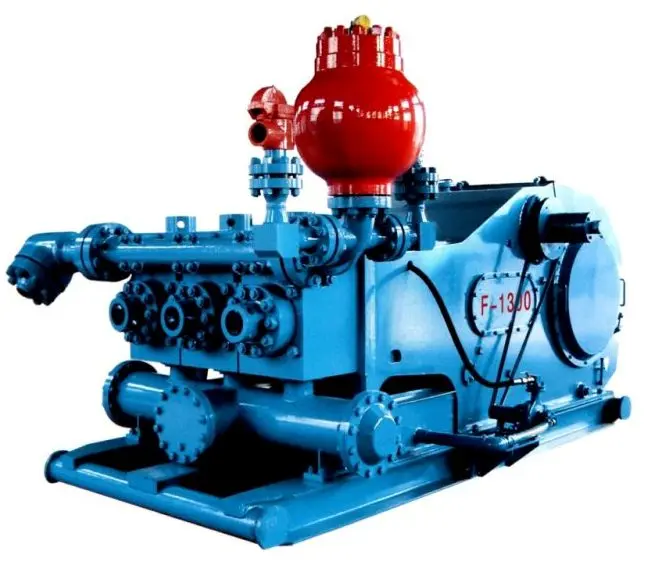
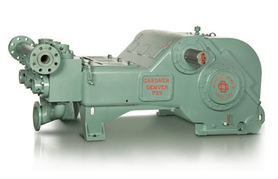
The NOV FC-1600 Triplex Mud Pump is made of rugged Fabriform construction and designed for optimum performance under extreme drilling conditions. It is compact and occupies less space, yet delivers unequaled performance. The pumps are backed by several decades of design and manufacturing experience, and are considered leaders in the field.
NOV FC-1600 Triplex Mud Pump is conservatively rated at relatively low rpm. This reduces the number of load reversals in heavily stressed components and increases the life of the fluid end parts through conservative speeds and valve operation.
The NOV FC-1600 Triplex Mud Pump design provides an inherently balanced assembly. No additional counterbalancing is required for smooth operation. No inertia forces are transmitted to the pumps’ mountings.
A Triplex Mud Pump sometimes referred to as a drilling mud pump or mud drilling pump. NOV FC-1600 Triplex Mud Pump is a reciprocating piston/plunger pump designed to circulate drilling fluid under high pressure (up to 7,500 psi) down the drill string and back up the annulus. A mud pump is an important part of the equipment used for oil well drilling.

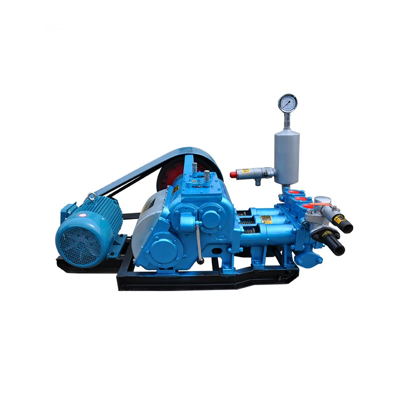
Since the NOV A1700-PT Triplex Mud Pump was built approximately 60 years ago, the industry has widely accepted the three cylinder or triplex style pump. Triplex mud pumps are manufactured worldwide, and many companies have emulated the original design and developed an improved form of the triplex pump in the past decade.
NOV A1700-PT Triplex Mud Pumps have many advantages they weight 30% less than a duplex of equal horsepower or kilowatts. The lighter weight parts are easier to handle and therefore easier to maintain. The other advantages include;They cost less to operate
One of the more important advantages of triplex over duplex pumps, is that they can move large volumes of mud at the higher pressure is required for modern deep hole drilling.
NOV A1700-PT Triplex Mud Pump is gradually phasing out duplex units. In a triplex pump, the pistons discharge mud only when they move forward in the liner. Then, when they moved back they draw in mud on the same side of the piston. Because of this, they are also called “single acting.” Single acting triplex pumps, pump mud at a relatively high speeds. NOV A1700-PT Triplex Mud Pump has three pistons each moving in its own liner. It also has three intake valves and three discharge valves. It also has a pulsation dampener in the discharge line.

If you ended up on this page doing normal allowed operations, please contact our support at support@mdpi.com. Please include what you were doing when this page came up and the Ray ID & Your IP found at the
This website is using a security service to protect itself from online attacks. The action you just performed triggered the security solution. There are several actions that could trigger this block including submitting a certain word or phrase, a SQL command or malformed data.
If you are supplying pump supplies, you can find the most favorable prices at Alibaba.com. Whether you will be working with piston type or diaphragm type systems, reciprocating or centrifugal, Alibaba.com has everything you need. You can also shop for different sizes mud pump wholesale for your metering applications. If you operate a construction site, then you could need to find some concrete pump solutions that you can find at affordable rates at Alibaba.com. Visit the platform and browse through the collection of submersible and inline pump system, among other replaceable models.
A mud pump comes in different makes and sizes, and you buy the tool depending on the application. The pump used by a filling station is not the one you use to fill up your tanks. There are high flow rate low pressure systems used to transfer fluids axially. On the other hand, you can go with radial ones dealing with a low flow rate and high-pressure fluid. The mixed flow pump variety combines radial and axial transfer mechanisms and works with medium flow and pressure fluids. Depending on what it will be pumping, you can then choose the mud pump of choice from the collection at Alibaba.com.
Alibaba.com has been an excellent wholesale supplier of mud pump for years. The supply consists of a vast number of brands to choose from, comes in different sizes, operations, and power sources. You can get a pump for residential and large commercial applications from the collection. Whether you want a water pump for your home, or run a repair and maintenance business, and need a supply ofud pump, you can find the product you want from the vast collection at Alibaba.com.therther is refrigeration, air conditioning, transfer, or a simple car wash business, anything you want, Alibative.com can it you.

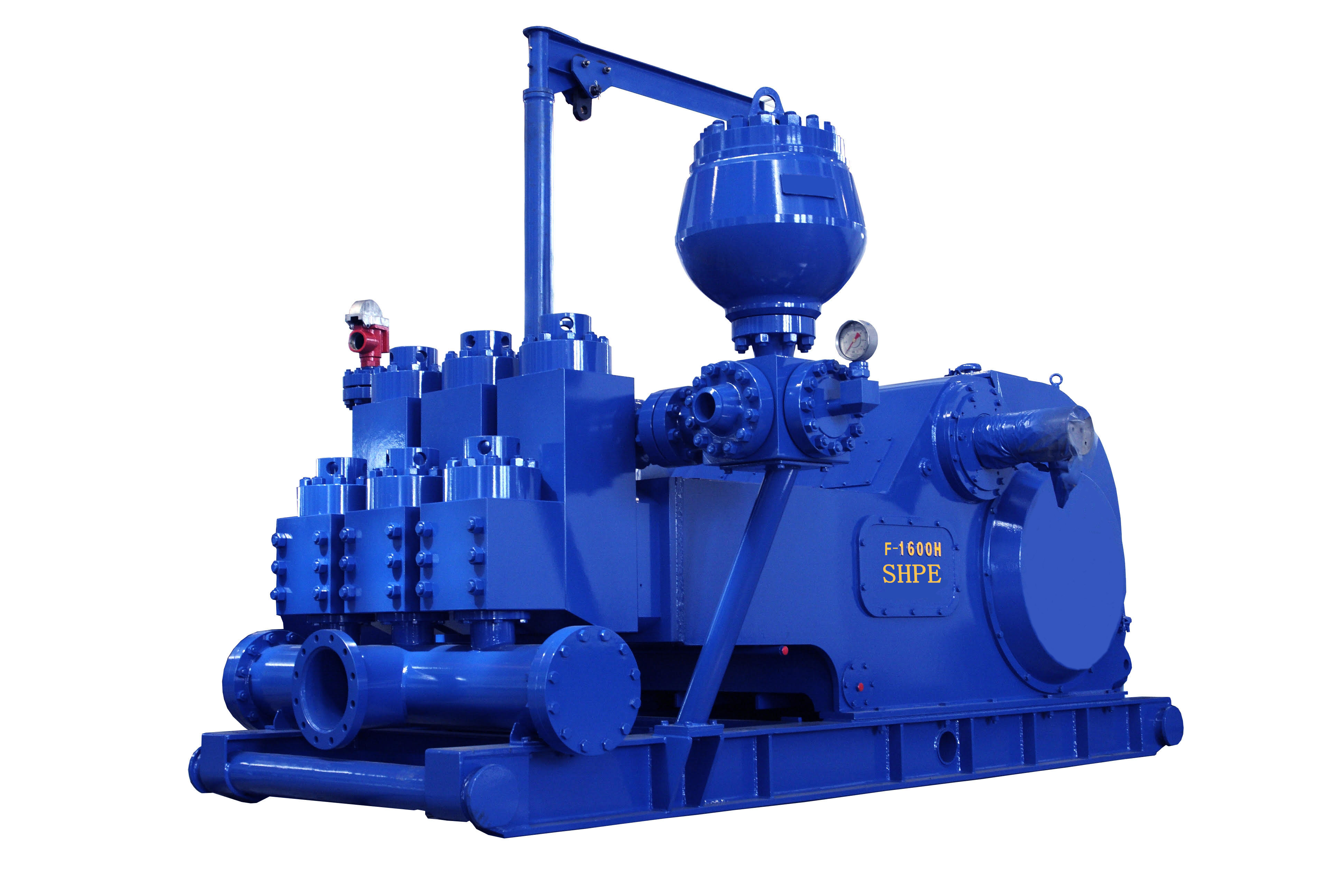
The 2,200-hp mud pump for offshore applications is a single-acting reciprocating triplex mud pump designed for high fluid flow rates, even at low operating speeds, and with a long stroke design. These features reduce the number of load reversals in critical components and increase the life of fluid end parts.
The pump’s critical components are strategically placed to make maintenance and inspection far easier and safer. The two-piece, quick-release piston rod lets you remove the piston without disturbing the liner, minimizing downtime when you’re replacing fluid parts.
Viscosity is critical in determining the selection and sizing of piping, valves, and motors. Using a friction loss chart will detail friction loss data for a given flow rate, pipe size, and fluid viscosity, helping you select the right components for your job. This information combined with available viscosity data will allow a proper analysis of the fluid process system characteristics. Once the fluid process system has been designed and the pump operating parameters defined, the proper pipeline selection can be made. When handling viscous fluids, it can be challenging to determine how they behave. Experience is paramount, as there is no substitute for actually working with these materials out in the field and seeing how they operate.
The EDDY Pump Corporation offers a full line of products that are specifically designed for high viscous fluids. If you are pumping slurry, high solids, extremely viscous material, paste, high abrasives (sand & gravel) and material filled with solids, then you found the best-suited pump for the job. Go to:
The EDDY Pump Corporation offers a full line of products that are specifically designed for high viscous fluids. If you are pumping slurry, high solids, extremely viscous material, paste, high abrasives (sand & gravel), and material filled with solids, then you found the best-suited pump for the job.Go to:https://eddypump.com/products/slurry-pumps/ Or Call Us!
When two (or more) pumps are arranged in serial their resulting pump performance curve is obtained by adding theirheads at the same flow rate as indicated in the figure below.
Centrifugal pumps in series are used to overcome larger system head loss than one pump can handle alone. for two identical pumps in series the head will be twice the head of a single pump at the same flow rate - as indicated with point 2.
With a constant flowrate the combined head moves from 1 to 2 - BUTin practice the combined head and flow rate moves along the system curve to point 3. point 3 is where the system operates with both pumps running
When two or more pumps are arranged in parallel their resulting performance curve is obtained by adding the pumps flow rates at the same head as indicated in the figure below.
Centrifugal pumps in parallel are used to overcome larger volume flows than one pump can handle alone. for two identical pumps in parallel and the head kept constant - the flow rate doubles compared to a single pump as indicated with point 2
Note! In practice the combined head and volume flow moves along the system curve as indicated from 1 to 3. point 3 is where the system operates with both pumps running
In practice, if one of the pumps in parallel or series stops, the operation point moves along the system resistance curve from point 3 to point 1 - the head and flow rate are decreased.
A large valve, usually installed above the ram preventers, that forms a seal in the annular space between the pipe and well bore. If no pipe is present, it forms a seal on the well bore itself. See blowout preventer.†
The space around a pipe in a well bore, the outer wall of which may be the wall of either the bore hole or the casing; sometimes termed the annular space.†
One or more valves installed at the wellhead to prevent the escape of pressure either in the annular space between the casing and the drill pipe or in open hole (for example, hole with no drill pipe) during drilling or completion operations. See annular blowout preventer and ram blowout preventer.†
A blowout preventer that uses rams to seal off pressure on a hole that is with or without pipe. It is also called a ram preventer. Ram-type preventers have interchangeable ram blocks to accommodate different O.D. drill pipe, casing, or tubing.†
A heavy, flanged steel fitting connected to the first string of casing. It provides a housing for slips and packing assemblies, allows suspension of intermediate and production strings of casing, and supplies the means for the annulus to be sealed off. Also called a spool.†
A pit in the ground to provide additional height between the rig floor and the well head to accommodate the installation of blowout preventers, ratholes, mouseholes, and so forth. It also collects drainage water and other fluids for disposal.†
The arrangement of piping and special valves, called chokes, through which drilling mud is circulated when the blowout preventers are closed to control the pressures encountered during a kick.†
A centrifugal device for removing sand from drilling fluid to prevent abrasion of the pumps. It may be operated mechanically or by a fast-moving stream of fluid inside a special cone-shaped vessel, in which case it is sometimes called a hydrocyclone.†
A centrifugal device, similar to a desander, used to remove very fine particles, or silt, from drilling fluid. This keeps the amount of solids in the fluid to the lowest possible level.†
A small enclosure on the rig floor used as an office for the driller or as a storehouse for small objects. Also, any small building used as an office or for storage.†
The hoisting mechanism on a drilling rig. It is essentially a large winch that spools off or takes in the drilling line and thus raises or lowers the drill stem and bit.†
The cutting or boring element used in drilling oil and gas wells. Most bits used in rotary drilling are roller-cone bits. The bit consists of the cutting elements and the circulating element. The circulating element permits the passage of drilling fluid and uses the hydraulic force of the fluid stream to improve drilling rates.†
A heavy, thick-walled tube, usually steel, used between the drill pipe and the bit in the drill stem. It is used to put weight on the bit so that the bit can drill.†
The heavy seamless tubing used to rotate the bit and circulate the drilling fluid. Joints of pipe 30 feet long are coupled together with tool joints.†
A wire rope hoisting line, reeved on sheaves of the crown block and traveling block (in effect a block and tackle). Its primary purpose is to hoist or lower drill pipe or casing from or into a well. Also, a wire rope used to support the drilling tools.†
On diesel electric rigs, powerful diesel engines drive large electric generators. The generators produce electricity that flows through cables to electric switches and control equipment enclosed in a control cabinet or panel. Electricity is fed to electric motors via the panel.†
A large, hook-shaped device from which the elevator bails or the swivel is suspended. It is designed to carry maximum loads ranging from 100 to 650 tons and turns on bearings in its supporting housing.†
The heavy square or hexagonal steel member suspended from the swivel through the rotary table. It is connected to the topmost joint of drill pipe to turn the drill stem as the rotary table turns.†
A device fitted to the rotary table through which the kelly passes. It is the means by which the torque of the rotary table is transmitted to the kelly and to the drill stem. Also called the drive bushing.†
A portable derrick capable of being erected as a unit, as distinguished from a standard derrick, which cannot be raised to a working position as a unit.†
The derrickman"s working platform. Double board, tribble board, fourable board; a monkey board located at a height in the derrick or mast equal to two, three, or four lengths of pipe respectively.†
Shallow bores under the rig floor, usually lined with pipe, in which joints of drill pipe are temporarily suspended for later connection to the drill string.†
A series of open tanks, usually made of steel plates, through which the drilling mud is cycled to allow sand and sediments to settle out. Additives are mixed with the mud in the pit, and the fluid is temporarily stored there before being pumped back into the well. Mud pit compartments are also called shaker pits, settling pits, and suction pits, depending on their main purpose.†
A trough or pipe, placed between the surface connections at the well bore and the shale shaker. Drilling mud flows through it upon its return to the surface from the hole.†
A diesel, Liquefied Petroleum Gas (LPG), natural gas, or gasoline engine, along with a mechanical transmission and generator for producing power for the drilling rig. Newer rigs use electric generators to power electric motors on the other parts of the rig.†
A hole in the rig floor 30 to 35 feet deep, lined with casing that projects above the floor. The kelly is placed in the rathole when hoisting operations are in progress.†
Shallow bores under the rig floor, usually lined with pipe, in which joints of drill pipe are temporarily suspended for later connection to the drill string.†
A mud pit in which a supply of drilling fluid has been stored. Also, a waste pit, usually an excavated, earthen-walled pit. It may be lined with plastic to prevent soil contamination.†
The hose on a rotary drilling rig that conducts the drilling fluid from the mud pump and standpipe to the swivel and kelly; also called the mud hose or the kelly hose.†
The principal component of a rotary, or rotary machine, used to turn the drill stem and support the drilling assembly. It has a beveled gear arrangement to create the rotational motion and an opening into which bushings are fitted to drive and support the drilling assembly.
A series of trays with sieves or screens that vibrate to remove cuttings from circulating fluid in rotary drilling operations. The size of the openings in the sieve is selected to match the size of the solids in the drilling fluid and the anticipated size of cuttings. Also called a shaker.†
Wedge-shaped pieces of metal with teeth or other gripping elements that are used to prevent pipe from slipping down into the hole or to hold pipe in place. Rotary slips fit around the drill pipe and wedge against the master bushing to support the pipe. Power slips are pneumatically or hydraulically actuated devices that allow the crew to dispense with the manual handling of slips when making a connection. Packers and other down hole equipment are secured in position by slips that engage the pipe by action directed at the surface.†
A relatively short length of chain attached to the tong pull chain on the manual tongs used to make up drill pipe. The spinning chain is attached to the pull chain so that a crew member can wrap the spinning chain several times around the tool joint box of a joint of drill pipe suspended in the rotary table. After crew members stab the pin of another tool joint into the box end, one of them then grasps the end of the spinning chain and with a rapid upward motion of the wrist "throws the spinning chain"-that is, causes it to unwrap from the box and coil upward onto the body of the joint stabbed into the box. The driller then actuates the makeup cathead to pull the chain off of the pipe body, which causes the pipe to spin and thus the pin threads to spin into the box.†
A vertical pipe rising along the side of the derrick or mast. It joins the discharge line leading from the mud pump to the rotary hose and through which mud is pumped going into the hole.†
A rotary tool that is hung from the rotary hook and traveling block to suspend and permit free rotation of the drill stem. It also provides a connection for the rotary hose and a passageway for the flow of drilling fluid into the drill stem.†
The large wrenches used for turning when making up or breaking out drill pipe, casing, tubing, or other pipe; variously called casing tongs, rotary tongs, and so forth according to the specific use. Power tongs are pneumatically or hydraulically operated tools that spin the pipe up and, in some instances, apply the final makeup torque.†
The top drive rotates the drill string end bit without the use of a kelly and rotary table. The top drive is operated from a control console on the rig floor.†
v: 1. to assemble and join parts to form a complete unit (for example, to make up a string of drill pipe). 2. to screw together two threaded pieces. Compare break out. 3. to mix or prepare (for example, to make up a tank of mud). 4. to compensate for (for example, to make up for lost time).
n: a device that is attached to the shaft of the drawworks and used as a power source for making up joints of pipe. It is usually located on the driller’s side of the drawworks. Also called spinning cathead.
n: 1. an accessory system of piping to a main piping system (or another conductor) that serves to divide a flow into several parts, to combine several flows into one, or to reroute a flow to any one of several possible destinations.
n: a device that fits into the rotary table to accommodate the slips and drive the kelly bushing so that the rotating motion of the rotary table can be transmitted to the kelly.
n: a percussion tool operated mechanically to give an upward thrust to a fish by the sudden release of a tripping device inside the tool. If the fish can be freed by an upward blow, the mechanical jar can be very effective.
n: a drilling rig in which the source of power is one or more internal-combustion engines and in which the power is distributed to rig components through mechanical devices (such as chains, sprockets, clutches, and shafts). Also called a power rig. Compare electric rig.
n: a method of enhanced recovery in which various hydrocarbon solvents or gases (such as propane, LPG, natural gas, carbon dioxide, or a mixture thereof) are injected into the reservoir to reduce interfacial forces between oil and water in the pore channels and thus displace oil from the reservoir rock. See chemical flooding, gas injection.
n: any of various power units, such as a hydraulic, internal combustion, air, or electric device, that develops energy or imparts motion. Compare engine.
n: an employee of a drilling fluid supply company whose duty it is to test and maintain the drilling mud properties that are specified by the operator.
n: the recording of information derived from examination and analysis of formation cuttings made by the bit and of mud circulated out of the hole. A portion of the mud is diverted through a gas-detecting device. Cuttings brought up by the mud are examined under ultraviolet light to detect the presence of oil or gas. Mud logging is often carried out in a portable laboratory set up at the well site.
n: a measure of the density of a drilling fluid expressed as pounds per gallon, pounds per cubic foot, or kilograms per cubic metre. Mud weight is directly related to the amount of pressure the column of drilling mud exerts at the bottom of the hole.
n: an arrangement for producing a well in which one wellbore penetrates two or more petroleum-bearing formations. In one type, multiple tubing strings are suspended side by side in the production casing string, each a different length and each packed to prevent the commingling of different reservoir fluids. Each reservoir is then produced through its own tubing string. Alternatively, a small diameter production casing string may be provided for each reservoir, as in multiple miniaturized or multiple tubingless completions. See dual completion.

This example uses many supporting files that are stored in a zip file. Unzip the file to get access to the supporting files, load the model parameters, and create the reciprocating pump library.
Generating Simulink library "mech_hydro_forcesPS_lib" in the current directory "L:\misc\ExampleManager\anarasim.bdoc22b_triplexpump\predmaint-ex92746726" ...
The pump model is configured to model three types of faults; cylinder leaks, blocked inlet, and increased bearing friction. These faults are parameterized as workspace variables and configured through the pump block dialog.
The pump model is configured to include noise, thus running the model with the same fault parameter values will result in different simulation outputs. This is useful for developing a classifier as it means there can be multiple simulation results for the same fault condition and severity. To configure simulations for such results, create vectors of fault parameter values where the values represent no faults, a single fault, combinations of two faults, and combinations of three faults. For each group (no fault, single fault, etc.) create 125 combinations of fault values from the fault parameter values defined above. This gives a total of 1000 combinations of fault parameter values. Note that running these 1000 simulations in parallel takes around an hour on a standard desktop and generates around 620MB of data. To reduce simulation time, reduce the number of fault combinations to 20 by changing runAll = true to runAll = false. Note that a larger dataset results in a more robust classifier.
Use the fault parameter combinations to create Simulink.SimulationInput objects. For each simulation input ensure that the random seed is set differently to generate different results.
Use the generateSimulationEnsemble function to run the simulations defined by the Simulink.SimulationInput objects defined above and store the results in a local sub-folder. Then create a simulationEnsembleDatastore from the stored results.
For each member in the ensemble preprocess the pump output flow and compute condition indicators based on the pump output flow. The condition indicators are later used for fault classification. For preprocessing remove the first 0.8 seconds of the output flow as this contains transients from simulation and pump startup. As part of the preprocessing compute the power spectrum of the output flow, and use the SimulationInput to return the values of the fault variables.
Configure the ensemble so that the read only returns the variables of interest and call the preprocess function that is defined at the end of this example.
The flow spectrum reveals resonant peaks at expected frequencies. Specifically, the pump motor speed is 950 rpm, or 15.833 Hz, and since the pump has 3 cylinders the flow is expected to have a fundamental at 3*15.833 Hz, or 47.5 Hz, as well as harmonics at multiples of 47.5 Hz. The flow spectrum clearly shows the expected resonant peaks. Faults in one cylinder of the pump will result in resonances at the pump motor speed, 15.833 Hz and its harmonics.
The flow spectrum and slow signal gives some ideas of possible condition indicators. Specifically, common signal statistics such as mean, variance, etc. as well as spectrum characteristics. Spectrum condition indicators relating to the expected harmonics such as the frequency with the peak magnitude, energy around 15.833 Hz, energy around 47.5 Hz, energy above 100 Hz, are computed. The frequency of the spectral kurtosis peak is also computed.
Configure the ensemble with data variables for the condition indicators and condition variables for fault variable values. Then call the extractCI function to compute the features, and use the writeToLastMemberRead command to add the feature and fault variable values to the ensemble. The extractCI function is defined at the end of this example.
The above code preprocesses and computes the condition indicators for the first member of the simulation ensemble. Repeat this for all the members in the ensemble using the ensemble hasdata command. To get an idea of the simulation results under different fault conditions plot every hundredth element of the ensemble.
The previous section preprocessed and computed condition indicators from the flow signal for all the members of the simulation ensemble, which correspond to the simulation results for different fault combinations and severities. The condition indicators can be used to detect and classify pump faults from a pump flow signal.
Configure the simulation ensemble to read the condition indicators, and use the tall and gather commands to load all the condition indicators and fault variable values into memory
fPeak pLow pMid pHigh pKurtosis qMean qVar qSkewness qKurtosis qPeak2Peak qCrest qRMS qMAD qCSRange LeakFault BlockingFault BearingFault
The fault variable values for each ensemble member (row in the data table) can be converted to fault flags and the fault flags combined to single flag that captures the different fault status of each member.
Create a classifier that takes as input the condition indicators and returns the combined fault flag. Train a support vector machine that uses a 2nd order polynomial kernel. Use the cvpartition command to partition the ensemble members into a set for training and a set for validation.
The confusion plot shows for each combination of faults the number of times the fault combination was correctly predicted (the diagonal entries of the plot) and the number of times the fault combination was incorrectly predicted (the off-diagonal entries).
The confusion plot shows that the classifier did not correctly classify some fault conditions (the off diagonal terms). However, the no fault condition was correctly predicted. In a couple of places a no fault condition was predicted when there was a fault (the first column), otherwise a fault was predicted although it may not be exactly the correct fault condition. Overall the validation accuracy was 66% and the accuracy at predicting that there is a fault 94%.
Examine the cases where no fault was predicted but a fault did exist. First find cases in the validation data where the actual fault was a blocking fault but a no fault was predicted.
Examining the cases where no fault was predictive but a fault did exist reveals that they occur when the blocking fault value of 0.77 is close to its nominal value of 0.8, or the bearing fault value of 6.6e-5 is close to its nominal value of 0. Plotting the spectrum for the case with a small blocking fault value and comparing with a fault free condition reveals that spectra are very similar making detection difficult. Re-training the classifier but including a blocking value of 0.77 as a non fault condition would significantly improve the performance of the fault detector. Alternatively, using additional pump measurements could provide more information and improve the ability to detect small blocking faults.
This example showed how to use a Simulink model to model faults in a reciprocating pump, simulate the model under different fault combinations and severities, extract condition indicators from the pump output flow and use the condition indicators to train a classifier to detect pump faults. The example examined the performance of fault detection using the classifier and noted that small blocking faults are very similar to the no fault condition and cannot be reliably detected.

Triplex plunger-type mud pumps feature a reciprocating, positive displacement pump design utilizing three plungers to safely transfer high-viscosity fluids under high pressure over an extended depth. Although they have many industrial applications, these pumps have become an essential part of oil well drilling rigs where they’re used to provide smooth discharge of mud and debris from oil wells.
In addition to their use in drilling and well service operations, mud pumps are also frequently used to handle corrosive or abrasive fluids, as well as slurries containing relatively large particulates, in applications like commercial car washes, wastewater treatment, cementing, and desalination operations.
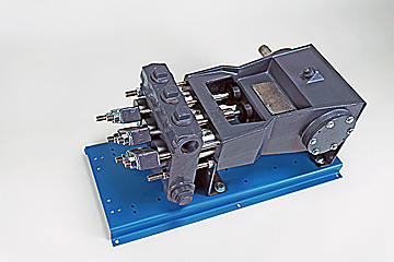
DAC Worldwide’s Representative Triplex, Plunger Mud Pump Dissectible (295-418) is an economical, conveniently-sized triplex plunger-type mud pump assembly that teaches learners hands-on maintenance activities commonly required on larger mud pump assemblies used in upstream oilfield production operations.
For example, mud pump assembly is used on well sites maintain downhole backpressure, to lubricate the rotating drill bit, and to help recycle and remove rock debris resulting from drilling activities. These heavy-duty, high-pressure pumps require regular refurbishment, inspection, and repair in the field.
DAC Worldwide’s dissectible mud pump assembly is a realistic sample that’s similar in geometry, design, and operating characteristics to the larger varieties learners will encounter on the job. DAC Worldwide chooses popular name-brand pumps for its dissectibles to ensure industrial and oil and gas training relevancy.
Using the dissectible mud pump, learners will gain hands-on experience with the operating principles, regular maintenance activities, and nomenclature/parts identification at a more convenient scale in the classroom or lab.
Technical training is most effective when learners can gain hands-on practice with industry-standard components they’ll encounter on the job. The Representative Triplex, Plunger Mud Pump Dissectible features a wide variety of common, industrial-quality components to provide learners with a realistic training experience that will build skills that translate easily to the workplace.
The Representative Triplex, Plunger Mud Pump Dissectible is a sturdy unit with a complete triplex, reciprocating, 20+ bhp plunger pump with .75" plunger, 1.5" stroke, and 3" cylinder sleeve. The unit allows for complete disassembly, assembly, and inspection, including removal of plungers, packing, and valves.
The dissectible mud pump comes with a formed-steel, powder-coated baseplate. It can also be mounted on a compatible DAC Worldwide Extended Electromechanical Workstation (903). Each unit comes with the manufacturer’s installation and maintenance manual.
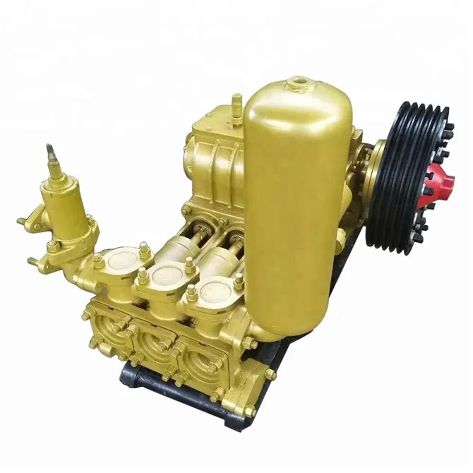
A mud pump (sometimes referred to as a mud drilling pump or drilling mud pump), is a reciprocating piston/plunger pump designed to circulate drilling fluid under high pressure (up to 7,500 psi or 52,000 kPa) down the drill string and back up the annulus. A mud pump is an important part of the equipment used for oil well drilling.
Mud pumps can be divided into single-acting pump and double-acting pump according to the completion times of the suction and drainage acting in one cycle of the piston"s reciprocating motion.
Mud pumps come in a variety of sizes and configurations but for the typical petroleum drilling rig, the triplex (three piston/plunger) mud pump is used. Duplex mud pumps (two piston/plungers) have generally been replaced by the triplex pump, but are still common in developing countries. Two later developments are the hex pump with six vertical pistons/plungers, and various quintuplexes with five horizontal piston/plungers. The advantages that these new pumps have over convention triplex pumps is a lower mud noise which assists with better measurement while drilling (MWD) and logging while drilling (LWD) decoding.
The fluid end produces the pumping process with valves, pistons, and liners. Because these components are high-wear items, modern pumps are designed to allow quick replacement of these parts.
To reduce severe vibration caused by the pumping process, these pumps incorporate both a suction and discharge pulsation dampener. These are connected to the inlet and outlet of the fluid end.
The power end converts the rotation of the drive shaft to the reciprocating motion of the pistons. In most cases a crosshead crank gear is used for this.
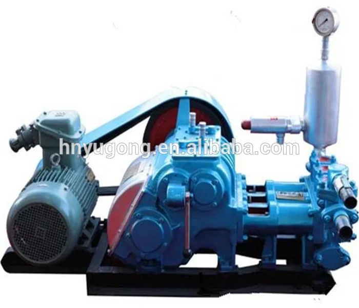
Displacement is calculated as discharged liters per minute. It is related to the drilling hole diameter and the return speed of drilling fluid from the bottom of the hole, i.e. the larger the diameter of drilling hole, the larger the desired displacement. The return speed of drilling fluid should wash away the debris and rock powder cut by the drill from the bottom of the hole in a timely manner, and reliably carry them to the earth"s surface. When drilling geological core, the speed is generally in range of 0.4 to 1.0 m^3/min.
The pressure of the pump depends on the depth of the drilling hole, the resistance of flushing fluid (drilling fluid) through the channel, as well as the nature of the conveying drilling fluid. The deeper the drilling hole and the greater the pipeline resistance, the higher the pressure needed.
With the changes of drilling hole diameter and depth, the displacement of the pump can be adjusted accordingly. In the mud pump mechanism, the gearbox or hydraulic motor is equipped to adjust its speed and displacement. In order to accurately measure the changes in pressure and displacement, a flow meter and pressure gauge are installed in the mud pump.
The construction department should have a special maintenance worker that is responsible for the maintenance and repair of the machine. Mud pumps and other mechanical equipment should be inspected and maintained on a scheduled and timely basis to find and address problems ahead of time, in order to avoid unscheduled shutdown. The worker should attend to the size of the sediment particles; if large particles are found, the mud pump parts should be checked frequently for wear, to see if they need to be repaired or replaced. The wearing parts for mud pumps include pump casing, bearings, impeller, piston, liner, etc. Advanced anti-wear measures should be adopted to increase the service life of the wearing parts, which can reduce the investment cost of the project, and improve production efficiency. At the same time, wearing parts and other mud pump parts should be repaired rather than replaced when possible.

I’ve run into several instances of insufficient suction stabilization on rigs where a “standpipe” is installed off the suction manifold. The thought behind this design was to create a gas-over-fluid column for the reciprocating pump and eliminate cavitation.
When the standpipe is installed on the suction manifold’s deadhead side, there’s little opportunity to get fluid into all the cylinders to prevent cavitation. Also, the reciprocating pump and charge pump are not isolated.
The gas over fluid internal systems has limitations too. The standpipe loses compression due to gas being consumed by the drilling fluid. In the absence of gas, the standpipe becomes virtually defunct because gravity (14.7 psi) is the only force driving the cylinders’ fluid. Also, gas is rarely replenished or charged in the standpipe.
Installing a suction stabilizer from the suction manifold port supports the manifold’s capacity to pull adequate fluid and eliminates the chance of manifold fluid deficiency, which ultimately prevents cavitation.
Another benefit of installing a suction stabilizer is eliminating the negative energies in fluids caused by the water hammer effect from valves quickly closing and opening.
The suction stabilizer’s compressible feature is designed to absorb the negative energies and promote smooth fluid flow. As a result, pump isolation is achieved between the charge pump and the reciprocating pump.
The isolation eliminates pump chatter, and because the reciprocating pump’s negative energies never reach the charge pump, the pump’s expendable life is extended.
Investing in suction stabilizers will ensure your pumps operate consistently and efficiently. They can also prevent most challenges related to pressure surges or pulsations in the most difficult piping environments.
Sigma Drilling Technologies’ Charge Free Suction Stabilizer is recommended for installation. If rigs have gas-charged cartridges installed in the suction stabilizers on the rig, another suggested upgrade is the Charge Free Conversion Kits.


 8613371530291