
relief valve for mud pump free sample

This website is using a security service to protect itself from online attacks. The action you just performed triggered the security solution. There are several actions that could trigger this block including submitting a certain word or phrase, a SQL command or malformed data.
A wide variety of pressure relief valve for mud pump options are available to you, You can also choose from new, pressure relief valve for mud pump,As well as from energy & mining, construction works , and machinery repair shops. And whether pressure relief valve for mud pump is 1.5 years, 3 months, or {3}.

Relief valve mud pump is also called the centrifugal pump, a compressor, and a compressor. It has a series of pistons, this is done in the form of a centrifugal pump, with a compressor. It is usually used by hydraulic maintenance. The rotating pumps have different cuffs and suction cuffs.@@@@@
Relief valve mud pumps are specially designed for the rotation of the vehicle. There are many types of relief valve mud pumps, suitable for a rotating purpose, such as electric relief valve mud pumps. In the case of the different, pumps are suitable for a rotating process. They are suitable for rotating, there are various sizes and varieties of the pumps depending on the rotation pattern, but with a lesser water flow. On the other hand, there are various types of relief valve mud pumps that are specially designed for use in rotating processes. If the pump is suitable for a rotary motion, these pumps are suitable for a rotary process, and can be used on both sides of the vehicle. On Alibaba.com, there are various types of relief valve mud pumps, such as electric relief valve mud.

For 50 years, Giant Pumps has offered the most dependable positive displacement high-pressure triplex pumps available. Designed and built to the highest quality standards, customers count on Giant Pumps products to keep their equipment running. Every design detail of Giant Pumps products is optimized for long-life and reliable performance, making Giant Pumps the most trusted name in high-pressure pumps and systems.

What"s the best way to avoid trouble? Seek the path of least resistance. While this may not be the best advice for all situations, it is helpful for us to know that fluids follow this cliché with predictable behavior. Applying this knowledge to your pump/system can prevent expensive downtime when component failure is caused by unavoidable or unexpected high pressure spikes. How do you compensate for high pressure spikes? A simple, but very effective, way is to install a relief valve.
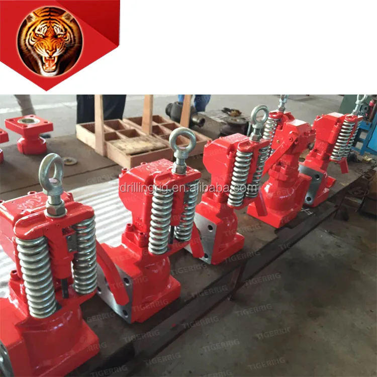
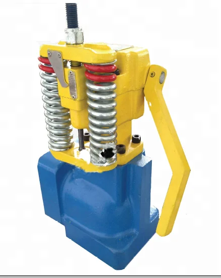
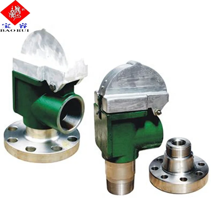
The relief valve (also called a bypass valve) is a mechanism used to control or limit pressure by allowing the fluid to flow into an auxiliary passage, away from the main flow path. The relief valve is designed or set to activate at a predetermined pressure. When this pressure setting is exceeded, the relief valve becomes the “path of least resistance” as the valve is forced open and a portion of the fluid is diverted through the auxiliary route. The diverted fluid is usually returned back to either the reservoir or the pump inlet. Generally, the relief valve is used as a safety precaution bysetting a limit for the maximum operating pressure of the system or pump, ready to operate should the system exceed its pressure limits. The relief valve and bypass path can be internal (an integral part of the pump) or external (installed as a component in the fluid path).
An internal bypass simply recirculates the fluid within the pump, returning the fluid from the outlet chamber to the inlet chamber. Cut-away views of a Series GJ and GB pump (see Fig. 1) show how discharge fluid fills the magnet cup. As the discharge pressure on the outlet side of the pump increases, so does the pressure within the magnet cup. When this pressure exceeds the force of the bypass spring holding down the poppet, it pushes the poppet off its "seat," allowing fluid to move through the auxiliary passage to the pump inlet. Bypass spring tension (and, consequently, bypass opening pressure) can be increased or decreased externally by adjusting the bypass screw (see Fig. 1).
This recirculation of fluid takes place in a small area (Fig. 1a) of the bypass. When the bypass remains open and the fluid is recirculated over a prolonged period, the energy of fluid movement and fluid friction will cause an increase in fluid temperature. Users should be aware that even when the fluid temperature in the system does not exceed recommended values, bypass conditions may create a sufficient temperature rise to cause significant swelling in PTFE-geared pumps. Fluid heating is a primary concern when the bypass is used to recirculate a large percentage of pumped fluid in small volume, closed-loop systems.
The external bypass is created by installing a relief valve in the system. Relief valves are available from several sources and typically operate on the same principle as explained previously: a poppet held in place with a spring is activated when the fluid pressure overcomes the force exerted by the spring. An external bypass is usually designed with the relief valve located close to the pump outlet and upstream of any other valves in the system. The diverted fluid should be directed back to the supply reservoir to avoid any possibility of fluid temperature problems as described previously. Figure 2 shows a possible bypass configuration.
Closed bypass This is when the relief valve is closed. In our pumps, this occurs when the adjusting screw is turned all the way in (clockwise), compressing the bypass spring all the way, and the pump experiences full-flow and pressure-producing capabilities.
Full-flow bypass pressure This is the fluid pressure when maximum flow is passing through the relief valve and bypass path. In our pumps, 100% of the bypass output is recirculated.
Relief valves should be “set” to open at a pressure above the operating pressure. This provides system safety. Care should be taken when determining the maximum system pressure. Use the component with the lowest pressure rating as a guide for establishing your limit. Don"t forget, this component could be the tubing!
In fluid handling applications, many markets have systems where high flow/low pressure is needed in one phase, followed by low flow/high pressure needs in the next phase. As always, the system and pump designer must conserve power, prevent temperature increases, and provide reliable solutions immediately (or sooner). The bypass valve offers a means of solving system problems and providing safety in a practical manner, without breaking tight budgets. So consider the path of least resistance on the way to your next solution. You may find relief!

The 2,200-hp mud pump for offshore applications is a single-acting reciprocating triplex mud pump designed for high fluid flow rates, even at low operating speeds, and with a long stroke design. These features reduce the number of load reversals in critical components and increase the life of fluid end parts.
The pump’s critical components are strategically placed to make maintenance and inspection far easier and safer. The two-piece, quick-release piston rod lets you remove the piston without disturbing the liner, minimizing downtime when you’re replacing fluid parts.
V, VB, and VL series 2-, 3-, and 5-valve instrument manifolds; VE series 2-, 3-, and 5-valve direct-mount manifolds; 2-valve remote-mount manifolds;Mod 85 modular instrumentation systems
Packless valves with all-metal seal to atmosphere; Working pressures up to 3500 psig (241 bar); Temperatures up to 400°F (204°C); VCR® face seal fitting, Swagelok® tube fitting, and weld end connections
Features: Modified PTFE wetted components meet SEMI Standard F57-0301 for ultrahigh-purity system components; Fine thread flare and Nippon Pillar® Super 300 end connections; Low cracking and reseal pressure
Rugged, all-stainless steel construction; Reverse flow coefficient less than 0.1 % of forward flow coefficient; No springs or elastomers; Compact size
Features: Working pressures up to 3000 psig (206 bar); Temperatures up to 400°F (204°C) with standard PTFE packing, up to 600°F (315°C) with optional Grafoil® packing; Straight and angle-pattern valves
Swagelok thermal-immersion diaphragm valves offer high-speed actuation and are designed for optimum performance at 220 degrees C (428 degrees F) for high-temperature processes.
Features: Suitable for ultrahigh-purity applications;316L VIM-VAR stainless steel body; Low-pressure and high-pressure models; VCR®, tube butt weld, and modular surface-mount end connections; Manual or pneumatic actuation
Features: Quarter-turn operation and full flow design; Light in weight; High-purity PFA material with low extractables for chemical resistance; 1/4 in. Swagelok® PFA tube fitting end connections for consistent performance
ALD 3, 6, and 7 Diaphragm Valves and ALD20 Bellows: Ultrahigh cycle life, high-speed actuation; Up to 392°F (200°C) w thermal actuators; Electronic actuator position-sensing; ultrahigh-purity applications; High flow capacity, PFA seat, Normally closed pneumatic actuation, Alloy 22 available
Features: 316L stainless steel and modified PTFE wetted parts; Variety of compact multivalve, multiport configurations; Choice of sanitary clamp and butt weld end connections; Choice of pneumatic or manual actuators in plastic or aluminum; Five sizes from 1/2 to 2 in.
Features: Pneumatic and quarter-turn manual 2-way and 3-way models; pneumatic and manual models with adjustable flow and bypass features; DuPont® Teflon® modified PTFE wetted parts and polypropylene actuator; Meet SEMI Standard F57-0301 for ultrahigh-purity system components; Fine thread flare and Nippon Pillar® Super 300 end connections standard; space saver and other end connections available; Custom manifolds and subassemblies available
Features: All-welded design provides reliable containment of system fluid; Forward flow starts at less than 2 psig (0.14 bar) pressure differential; Valve closes with less than 2 psig (0.14 bar) back pressure; 316L SS body offers enhanced material purity
Features: Working pressures up to 300 psig (20.6 bar); Shutoff, bulk-gas distribution, and isolation service; Cast, forged, and bar stock stainless steel body material; 1/4 to 1 in. and 12 to 25 mm end connections
Features: stainless steel, carbon steel, and duplex stainless steel materials; pressure ratings in accordance with ASME B16.5; flanged connections compatible with ASME B16.5; ball valve bore sizes from 3/8 to 2 in. (9.5 to 50.8 mm)
Features: Packless valves with all-metal seal to atmosphere; Working pressures up to 500 psig (34.4 bar); Temperatures up to 200°F (93°); 1/4 to 1/2 in. and 6 to 12 mm end connections
Features: Roddable, straight-through orifice for maximum flow; Working pressures up to 6000 psig (413 bar); Packing below the threads; Replaceable seat and stem tip design
Features: The Swagelok® compact gauge valve provides fast, convenient installation and installation and gauge maintenance in a lightweight package and smaller footprint than conventional assemblies.
Features: Compact, packless valve switches flow from one line to another. Torlon® stem guide ensures proper alignment for consistent shutoff performance. Manual and spring-return and double-acting pneumatic actuators are available. End connections include 1/4 in. Swagelok® VCR® metal gasket face seal fittings and 1/4 in. Swagelok tube fittings.
Features: 316 stainless steel materials; Union-bonnet construction for safety; Grafoil® packing for high-temperature performance; Swagelok® tube fitting, female NPT, and tube or pipe socket weld end connections
Features: Limits access to manually actuated valves;Lockout accessory enables compliance with OSHA Lockout/Tagout, Standard 29 CFR Part 1910.147, Control of Hazardous Energy Bright safety orange color promotes high visibility. Other colors are available.
Features: Micrometer handle for precise, repeatable flow settings; Working pressures up to 700 psig (48.2 bar); Temperatures up to 900°F (482°C); 316 stainless steel construction
GB series ball valves; Working pressures up to 6250 psig (430 bar) with temperatures from –40 to 248˚F (–40 to 120˚C); Swagelok® tube fitting end connections, 3/8 in. to 1 in. female pipe, and fractional or metric (12 mm to 25 mm); Corrosion-resistant body materials: 316/316L, Alloy 2507, 6-Moly, Alloy 625, Alloy 825, Alloy C-276; Optional API 607 for fire-safe applications and NACE MR0175/ISO 15156 for sour gas
Features: 1/8 to 2 in. and 6 to 25 mm sizes; Stainless steel, carbon steel, brass, and special alloy materials; On-off (2-way) and switching (3-way) valves; Compensating seat design; Live-loaded, two-piece stem packing
Features: 3/8 to 1 in. sizes; alloy 625, alloy 825, Alloy 2507, and alloy 6-moly materials; On-off (2-way) valves; Compensating seat design; Live-loaded, two-piece stem packing
Bleed Valves: Working pressures up to 10 000 psig (689 bar); Temperatures up to 850°F (454°C); 316 stainless steel, carbon steel, alloy 400, or alloy C-276 materials. Purge Valves: Working pressures up to 4000 psig (275 bar); Temperatures up to 600°F (315°C); 316 stainless steel, brass, or carbon steel materials
Features: 1.125 in. C-seal and W-seal designs; Available in two- and three-port configurations; Compact pneumatic and manual actuators; Pneumatic actuator indicator ball: red for normally closed, green for normally open; Fixed orientation of actuator to body for consistency of installation; Corner chamfers on outlet side of body for visual indication of flow direction
Features: Rack and pinion pneumatic actuators, solenoid valves, and limit switches; ISO 5211-compliant pneumatic actuators, solenoid valves, limit switches, and position sensors; Complete actuated assemblies and kits for field assembly available
Features: Alloy 625, alloy 825, and Alloy 2507 super duplex stainless steel materials; Available for CH4 adn Ch8 series check valves; Working pressures up to 6 000 psig (413 bar); 1/4 to 1/2 in. Swagelok tube fitting or NPT end connections;

This invention relates to the circulation of fluid between the surface of a subterranean well and the bore hole and more specifically relates to the simultaneous control of drilling fluid circulation or mud pumps and a choke communicating with the pump.
Conventional apparatus used in rotary drilling operations includes a drilling fluid circulation pump or mud pump used to circulate drilling fluids from the surface through the well bore. These fluids are used to remove cuttings made by a rotary drill. In normal drilling fluid or mud circulation, the drilling fluid is pumped down through the drill pipe, discharged through the bit and returns to the surface in the annular space outside the drill pipe and inside the drill hole and casing placed in the well. The rate of drilling fluid circulation is determined by the necessary upward flow velocity required for removing cavings and drill cuttings from the hole and by the jetting requirements of the bit. The inherent advantage of the rotary system of drilling is that a fluid is circulated for the purpose of removing drill cuttings and maintaining a hole in such condition that the drill string can be withdrawn readily and returned to the bottom whenever necessary.
During conventional drilling it is not uncommon to encounter a sudden pressure increase or kick caused by the release of downhole liquids or gases under pressure which can affect drilling fluid circulation. When a kick is encountered, it can be necessary to vary the rate at which drilling fluid is injected into the well or to change the weight of the drilling fluid. A choke, in communication with the pump, is used to prevent significant pressure changes in conjunction with a change in the speed of operation of the mud pumps. For example, a significant increase in downhole pressure occurring as a result of an increase in the drilling fluid circulation can conceivably fracture the producing formation causing serious damage.
In normal drilling operations, the mud pumps are controlled by the driller, using a driller"s console located at the driller"s station on a rig to monitor relevant drilling parameters, including the speed of the mud pumps. Furthermore, conventional well control circulation operations also require manipulation of the choke to regulate or control the fluid pressure, especially during changes in the speed of the mud pump. On a conventional drilling rig, the choke is normally controlled from a choke console, which can be positioned on the drilling floor, at a position remote from the normal location of a driller"s console on a surface rig. Simultaneous control of both the mud pumps and the choke requires communication between the driller and one manning the choke console. Such communication is difficult, especially on engine driven drilling rigs. The noise and the use of different types of gauges on a rig cause confusion and makes such communication difficult, especially on engine driven drilling rigs. Furthermore, a more accurate gauge for pump strokes rate is conventionally located at the choke console, but conventional apparatus provide no means for using this more accurate gauge at the choke console to control the pumps. In a crisis situation, where the drilling crew is attempting to control the well, increased emphasis is placed on efficient communication and operation, which is difficult using prior art devices.
Apparatus for controlling the circulation of well control or kill fluid in a subterranean well includes a pump and a choke communicating with the pump to deliver drilling fluids from the surface of the well into the bore hole and return to the fluid handling equipment. Apparatus for monitoring the condition of the pump is normally employed at the driller"s console on the drilling rig and such pump monitoring apparatus includes a conventional pump control for regulating the speed and operation of the drilling fluid pumps. These pump controls can consist of pneumatic control valves or rheostats.
While control of the pump can be effected from the driller"s console, control of the choke can be simultaneously effected using a choke control apparatus located at a choke console, normally located on the drilling floor at a location remote from the driller"s console. A second pump control apparatus, again consisting of a conventional device, such as a pneumatic control valve or a rheostat, is located at the choke monitoring console and can be used to regulate pump speed and operation in the same manner as the first pump control apparatus located at the driller"s console. Apparatus is provided for overriding the first pump control upon transmission of a signal from the second pump control. Such apparatus can comprise a pneumatic valve unit or an electrical relay consisting of normally closed and normally open switches which change state upon actuation of the second pump control apparatus. In the preferred embodiment of this invention, the overriding signal is the same as the pump control signal. When this pump control signal is transmitted, a valve or relay functions to override the first pump control apparatus. Signals transmitted from the second pump control located at the choke console can then be transmitted to the pumps.
In the preferred embodiment of this invention, the overriding apparatus comprises a portion of an interface network located in the driller"s console, and the second pump control signal is transmitted from the choke console through the driller"s console and subsequently to the drilling fluid or mud pumps. In this manner, control of both the pump and the choke can be transferred to the same location on the drilling rig to provide for better control over both the rate of circulation of the drilling fluids and over the pressure maintained in the bore hole. Such centralized control is quite useful in certain situations, such as when a kick is encountered.
The preferred embodiments of the invention depicted herein are intended for use with conventional driller"s consoles and choke consoles employed on diesel or electrically powered rigs commonly used for drilling subterranean wells. The interface network and remote pump control apparatus employed in the choke console are consistent with conventional commercially available components of driller"s consoles and choke console.
FIG. 1 shows the conventional location of the driller"s console 2 and choke console 4 between which signals are transmitted to regulate or control both mud pumps 6 and the choke 8. The choke console 4 located proximate to the choke 8 separately controls the operation of the choke. The driller"s console 2 includes means for separately controlling the mud pumps 6 and signals may be transmitted from the choke console to the driller"s console for regulating the operation and speed of the mud pump. It can be seen from FIG. 2 that in the preferred embodiment of this invention the choke console controls the pumps by signals transmitted through the driller"s console 2. The transmission of signals between the various components shown in FIG. 2 can be by any of a number of conventional means, such as by electrical signals, by pneumatic or hydraulic signals, by fiber optic signals, by power line modulation, or in any other conventional form suitable for use on a drilling rig. A pneumatic control network for use with a diesel powered rig and an electrical interface network for use within an electrically powered drilling rig will be described herein.
FIGS. 3-5 depict the operation of a pneumatic interface network for a diesel powered rig. Only those portions of the pump control and the interface network relevant to the control of drilling fluid, circulating or mud pumps are depicted. Numerous other components are employed in a driller"s console or in a choke console. Such components are, however, conventional and the components shown in FIG. 3 are compatible with other conventional components controlling the operation of a drilling rig. The pneumatic interface network for the diesel powered rig shown in FIG. 3 is intended for use in controlling two mud pumps. On conventional drilling rigs, two or more mud pumps are employed, although it is common practice to use only a single mud pump at a time, retaining the other mud pumps for redundancy and/or for emergency situations. The two pneumatic control valves 12 and 26 contained within the driller"s console comprise conventional valves commonly employed in driller"s console. Valves manufactured by American Standard having a pressure range of 0 to 100 psi for clutch and throttle signals represent one conventional valve for controlling the mud pump. A plurality of shuttle valves 18, 20, 32 and 34, each comprising a dual input-single output valve, are employed on opposite sides of each of the first or main pneumatic control valves 12 and 26 for controlling the operation of the mud pumps. Shuttle valves 18, 20, 32 and 34 may comprise conventional valves, such as the P-54350-2 shuttle valve manufactured by Wabco, an American Standard Company. Of course other similar valves could be used to form the isolation function of these shuttle valves. Valve 70, also located at the driller"s console, comprises a four element stack valve unit consisting of valve elements 70a, 70b, 70c and 70d. Pneumatic valves 70 each comprise spring loaded, dual input, single output valves forming a valve stack 70. Individual valves are of conventional construction and comprise valves such as the A222PS valves manufactured by ARO Inc. which can be secured together by using an MKN stacking kit and an isolator plate manufactured by ARO Inc.
The pneumatic control valve 46 employed in the choke console comprises, in the preferred embodiment of this invention, an HD-2-FX pneumatic control valve having a pressure range from 0 to 100 psi, manufactured by American Standard. Pneumatic control valve 46 has a single input and three separate outputs. Valve 46 is located in the choke console and communicates with a conduit 40 providing air under pressure for use in actuating the various components depicted herein. A toggle switch 42 and an indicator light 44 are located on the choke console to insure that control is not transferred between the choke console and the driller"s console at a time when the differences in the throttle settings between the choke console and the driller"s console will create a serious pressure increase below the well, thus damaging the formation.
Three conduits 48, 50 and 52 extend from pneumatic control valve 46 to the driller"s console. Conduits 50 and 52 comprise the clutch C1 and clutch C2 signal paths for controlling the chokes 8 and communicate between the pneumatic control valve 46 and the individual valve units of stack valve 70. Clutch C1 line 52 is interconnected to shuttle valve element 20 and clutch C2 transmission line 50 is interconnected to shuttle valve 32. A T-conduit 54 is interconnected to the clutch C1 line 52 intermediate its ends and the T-conduit 54 establishes fluid communication between the clutch C1 line 52 and the first valve unit 70a. A separate branch 56 establishes communication between T-conduit 54 and another unit 70d of the stack. Each of the stack valves 70a-70d comprises a normally spring loaded valve in which the input from either rig air conduit 64 or from throttle valve line 48 passes directly through valve units 70a-70d. The T-conduit 54 and its adjoining conduit 56 lead from clutch line 52 and communicate with an actuator port on valve units 70a and 70d. Fluid pressure in conduit 54 and 56 serves to shift the pneumatic valve units 70a and 70d to close lines 64 or 48 when pressure is applied to clutch C1 conduit 52.
The clutch C2 line 50 extends the pneumatic control valve 46 into the driller"s console and communicates with shuttle valve 32. A T-conduit section 58 and branch 60 communicate with clutch C2 line 50 and with the remaining two valve units 70b and 70c at the actuator ports thereof. Pressure in clutch C2 line 50 will cause the valve units 70b and 70c to close against the action of a spring similarly disrupting the input from conduit 64 or 48 respectively.
The rig air input from conduit 64 into stack valve units 70a and 70b passes through lines 66 and 68 respectively to the pump control valves 12 and 26 when stack valves 70a and 70b are in the open position. Essentially, the stack valve units 70a and 70b are connected in parallel to the rig air source 64. The output conduits 61 and 62 leading from the stack valve units 70c and 70d are respectively connected to shuttle valves 18 and 34. Communication is normally established between throttle line 48 and valves 18 and 34 through the stack valve units 70c and 70d when the spring loaded valves are in their normally open position.
The first pneumatic control valves 12 and 26 comprise conventional elements for generating clutch and throttle signals in response to a constant pressure supply or rig air in conduit 64. For example, valve 12 generates a clutch signal in line 14 and a throttle signal in line 16. Clutch line 14 communicates with one of the two input ports of shuttle valve 20. Throttle line 16 communicates with one of the two input ports of shuttle valve 18.
FIG. 3 depicts a condition in which the mud pumps 6 and 6" can be controlled by using the first or primary mud pump controllers 12 and 26. It should be understood that in an actual practice, only one pump is normally used. Solid lines have been used to indicate that pneumatic signals communicate through the line, while dashed lines indicate that the line has been disabled and no signal is transmitted. As shown by the solid lines in FIG. 3, pressure in line 64, which is obtained from a source of rig air, communicates through the normally open stack valves 70a and 70b to lines 66 and 68 respectively. Rig air is then applied to pneumatic control valves 12 and 26. Referring to control valve 12, the presence of rig air at the input of this first control valve permits clutch and throttle signals to be generated in lines 14 and 16 respectively. Since the choke console pneumatic control valve is in the off position, as shown in FIG. 3, and there is no pressure in lines 48, 50 and 52, a pneumatic signal is applied in only one of the dual input ports of shuttle valves 18 and 20. A pneumatic clutch signal in line 14 can be transmitted through shuttle valve 20 and clutch line 22 directly to the drilling fluid or mud pump. Similarly, a throttle signal in line 16 would be transmitted through shuttle valve 18 and line 24 to the pump. Thus the pneumatic throttle and clutch signals to pump 6 are employed to control the operating speed of an internal combustion engine, for example, driving pump 6 and an operating clutch to engage or disengage the pump as desired or required.
FIG. 4 shows the condition in which the choke console pneumatic control valve 46 is actuated to apply a pneumatic signal in clutch line 52 and in throttle line 48. Pneumatic control valve 46 is of the type that actuation of a control lever in one direction will induce a clutch signal during initial movement and thereafter will produce a throttle signal. The pneumatic signal in clutch line 52 acts through lines 54 and 56 on the actuator ports of stack valve units 70a and 70d. Pressure applied at the actuator ports plugs the input lines to stack valve units 70a and 70d. Thus the rig air from line 64 is plugged by stack valve unit 70a thus disabling the first mud pump control valve 12 which comprises the primary means of regulating the mud pump 6 from the driller"s console. The pneumatic signal in line 52 is, however, transmitted to the second input port of shuttle valve 20. Since there is no pressure in line 14, any clutch signal in line 52 at shuttle valve 20 will be transmitted through line 22. The pneumatic signal in line 52 communicating with line 56 also disables the throttle input to stack valve unit 70d isolating shuttle valve 34 from the throttle line 48. Stack valve unit 70c, however, remains open and the pneumatic signal in throttle line 48 will be transmitted through line 61 to shuttle valve 18. This pneumatic signal in line 61 is in turn transmitted through throttle line 24 to the first mud pump. Similarly, the stack valve unit 70b remains open and rig air from conduit 64 flows through line 68 to the secondary driller mud pump control valve 26.
FIG. 5 shows the same pneumatic control circuit in which the choke console pump control valve 46 has been actuated to generate a pneumatic clutch C2 signal in line 50. This pneumatic signal in line 50 communicates through lines 58 and 60 to the actuating ports of stack valve units 70b and 70c to close the input ports from the rig air conduit 64 and from the throttle line 48 respectively. Valve units 70a and 70d, however, remain open. Rig air can thus be applied to pump control valve 12 and the pneumatic signal in throttle line 48 can be transmitted through stack valve unit 70d to one input port of shuttle valve 34. Similarly, the pneumatic signal in clutch C2 line 50 is transmitted to an input port of shuttle valve 32. A clutch signal derived from the pneumatic control valve 46 can thus be applied through line 36 to the second mud pump. Similarly, a throttle signal 38 determined by the position of pneumatic control valve 46 can be applied through shuttle valve 34 and line 38 to the second mud pump. Choke console pneumatic control valve 46 is of the type that actuation of an input lever in a first direction will apply a signal in clutch C1 line 52 and in throttle line 48, while actuation of the control valve unit in the opposite direction will result in the presence of a pneumatic signal in clutch C2 line 50 and in the throttle line 48. It will be understood that separate choke control elements are contained within the choke console for positioning the choke in the proper position. When the apparatus is in the configurations of FIGS. 4 and 5, the choke control valve 46 can also be used to control either mud pump 6 or mud pump 6".
FIG. 6 shows an electrical interface network for use with an electrically powered rig. Again, separate drillers and choke consoles can be used in the same manner as shown in FIG. 2. In this electrically powered network, rheostat 72 provides a control signal through path 88 and normally closed relay 84a and line 86 to an SCR housing for controlling the operation and speed of a single mud pump. A second rheostat 90 located on the choke console is normally isolated from SCR housing line 86 by a normally open relay 84b. The configuration of FIG. 6 shows the conventional operation of the mud pump 6 by means of the pump controlling rheostat 72 located in the driller"s console. When it is desired to control the mud pump by use of the choke mud pump control rheostat 90, switches 76 and 77 are closed. When switch 76 is closed, the relay 84 changes state and the normally open relay 84b is closed permitting regulation of the mud pump by the choke console mud pump rheostat 90. Closure of switch 76 results in the application of a voltage to the relay 84 thus changing the state of relays 84a and 84b to override the signal from the driller"s console mud pump rheostat 72 when it is desired to control the mud pump from the remote position of the choke console. Note that the common +V line 80 and ground line 82 lead between the driller"s console and the choke console. If for any reason these lines are severed, control of the mud pump automatically reverts to the driller"s console rheostat 72. Thus, the mud pump 6 or mud pump 6" can be controlled from the driller"s console or through the remote position of the choke console depending upon closure of electrical switch 76.
Although the invention has been described in terms of the specified embodiments which are set forth in detail, it should be understood that this is by illustration only and that the invention is not necessarily limited thereto, since alternative embodiments and operating techniques will become apparent to those skilled in the art in view of the disclosure. Accordingly, modifications are contemplated which can be made without departing from the spirit of the described invention.
Mechanical pumps serve in a wide range of applications such as pumping water from wells, aquarium filtering, pond filtering and aeration, in the car industry for water-cooling and fuel injection, in the energy industry for pumping oil and natural gas or for operating cooling towers and other components of heating, ventilation and air conditioning systems. In the medical industry, pumps are used for biochemical processes in developing and manufacturing medicine, and as artificial replacements for body parts, in particular the artificial heart and penile prosthesis.
When a pump contains two or more pump mechanisms with fluid being directed to flow through them in series, it is called a multi-stage pump. Terms such as two-stage or double-stage may be used to specifically describe the number of stages. A pump that does not fit this description is simply a single-stage pump in contrast.
In biology, many different types of chemical and biomechanical pumps have evolved; biomimicry is sometimes used in developing new types of mechanical pumps.
Pumps can be classified by their method of displacement into positive-displacement pumps, impulse pumps, velocity pumps, gravity pumps, steam pumps and valveless pumps. There are three basic types of pumps: positive-displacement, centrifugal and axial-flow pumps. In centrifugal pumps the direction of flow of the fluid changes by ninety degrees as it flows over an impeller, while in axial flow pumps the direction of flow is unchanged.
Some positive-displacement pumps use an expanding cavity on the suction side and a decreasing cavity on the discharge side. Liquid flows into the pump as the cavity on the suction side expands and the liquid flows out of the discharge as the cavity collapses. The volume is constant through each cycle of operation.
Positive-displacement pumps, unlike centrifugal, can theoretically produce the same flow at a given speed (rpm) no matter what the discharge pressure. Thus, positive-displacement pumps are constant flow machines. However, a slight increase in internal leakage as the pressure increases prevents a truly constant flow rate.
A positive-displacement pump must not operate against a closed valve on the discharge side of the pump, because it has no shutoff head like centrifugal pumps. A positive-displacement pump operating against a closed discharge valve continues to produce flow and the pressure in the discharge line increases until the line bursts, the pump is severely damaged, or both.
A relief or safety valve on the discharge side of the positive-displacement pump is therefore necessary. The relief valve can be internal or external. The pump manufacturer normally has the option to supply internal relief or safety valves. The internal valve is usually used only as a safety precaution. An external relief valve in the discharge line, with a return line back to the suction line or supply tank provides increased safety.
Rotary-type positive displacement: internal or external gear pump, screw pump, lobe pump, shuttle block, flexible vane or sliding vane, circumferential piston, flexible impeller, helical twisted roots (e.g. the Wendelkolben pump) or liquid-ring pumps
Drawbacks: The nature of the pump requires very close clearances between the rotating pump and the outer edge, making it rotate at a slow, steady speed. If rotary pumps are operated at high speeds, the fluids cause erosion, which eventually causes enlarged clearances that liquid can pass through, which reduces efficiency.
Hollow disk pumps (also known as eccentric disc pumps or Hollow rotary disc pumps), similar to scroll compressors, these have a cylindrical rotor encased in a circular housing. As the rotor orbits and rotates to some degree, it traps fluid between the rotor and the casing, drawing the fluid through the pump. It is used for highly viscous fluids like petroleum-derived products, and it can also support high pressures of up to 290 psi.
Vibratory pumps or vibration pumps are similar to linear compressors, having the same operating principle. They work by using a spring-loaded piston with an electromagnet connected to AC current through a diode. The spring-loaded piston is the only moving part, and it is placed in the center of the electromagnet. During the positive cycle of the AC current, the diode allows energy to pass through the electromagnet, generating a magnetic field that moves the piston backwards, compressing the spring, and generating suction. During the negative cycle of the AC current, the diode blocks current flow to the electromagnet, letting the spring uncompress, moving the piston forward, and pumping the fluid and generating pressure, like a reciprocating pump. Due to its low cost, it is widely used in inexpensive espresso machines. However, vibratory pumps cannot be operated for more than one minute, as they generate large amounts of heat. Linear compressors do not have this problem, as they can be cooled by the working fluid (which is often a refrigerant).
Reciprocating pumps move the fluid using one or more oscillating pistons, plungers, or membranes (diaphragms), while valves restrict fluid motion to the desired direction. In order for suction to take place, the pump must first pull the plunger in an outward motion to decrease pressure in the chamber. Once the plunger pushes back, it will increase the chamber pressure and the inward pressure of the plunger will then open the discharge valve and release the fluid into the delivery pipe at constant flow rate and increased pressure.
Pumps in this category range from simplex, with one cylinder, to in some cases quad (four) cylinders, or more. Many reciprocating-type pumps are duplex (two) or triplex (three) cylinder. They can be either single-acting with suction during one direction of piston motion and discharge on the other, or double-acting with suction and discharge in both directions. The pumps can be powered manually, by air or steam, or by a belt driven by an engine. This type of pump was used extensively in the 19th century—in the early days of steam propulsion—as boiler feed water pumps. Now reciprocating pumps typically pump highly viscous fluids like concrete and heavy oils, and serve in special applications that demand low flow rates against high resistance. Reciprocating hand pumps were widely used to pump water from wells. Common bicycle pumps and foot pumps for inflation use reciprocating action.
These positive-displacement pumps have an expanding cavity on the suction side and a decreasing cavity on the discharge side. Liquid flows into the pumps as the cavity on the suction side expands and the liquid flows out of the discharge as the cavity collapses. The volume is constant given each cycle of operation and the pump"s volumetric efficiency can be achieved through routine maintenance and inspection of its valves.
This is the simplest form of rotary positive-displacement pumps. It consists of two meshed gears that rotate in a closely fitted casing. The tooth spaces trap fluid and force it around the outer periphery. The fluid does not travel back on the meshed part, because the teeth mesh closely in the center. Gear pumps see wide use in car engine oil pumps and in various hydraulic power packs.
A screw pump is a more complicated type of rotary pump that uses two or three screws with opposing thread — e.g., one screw turns clockwise and the other counterclockwise. The screws are mounted on parallel shafts that have gears that mesh so the shafts turn together and everything stays in place. The screws turn on the shafts and drive fluid through the pump. As with other forms of rotary pumps, the clearance between moving parts and the pump"s casing is minimal.
Widely used for pumping difficult materials, such as sewage sludge contaminated with large particles, a progressing cavity pump consists of a helical rotor, about ten times as long as its width. This can be visualized as a central core of diameter x with, typically, a curved spiral wound around of thickness half x, though in reality it is manufactured in a single casting. This shaft fits inside a heavy-duty rubber sleeve, of wall thickness also typically x. As the shaft rotates, the rotor gradually forces fluid up the rubber sleeve. Such pumps can develop very high pressure at low volumes.
Named after the Roots brothers who invented it, this lobe pump displaces the fluid trapped between two long helical rotors, each fitted into the other when perpendicular at 90°, rotating inside a triangular shaped sealing line configuration, both at the point of suction and at the point of discharge. This design produces a continuous flow with equal volume and no vortex. It can work at low pulsation rates, and offers gentle performance that some applications require.
A peristaltic pump is a type of positive-displacement pump. It contains fluid within a flexible tube fitted inside a circular pump casing (though linear peristaltic pumps have been made). A number of rollers, shoes, or wipers attached to a rotor compresses the flexible tube. As the rotor turns, the part of the tube under compression closes (or occludes), forcing the fluid through the tube. Additionally, when the tube opens to its natural state after the passing of the cam it draws (restitution) fluid into the pump. This process is called peristalsis and is used in many biological systems such as the gastrointestinal tract.
These consist of a cylinder with a reciprocating plunger. The suction and discharge valves are mounted in the head of the cylinder. In the suction stroke, the plunger retracts and the suction valves open causing suction of fluid into the cylinder. In the forward stroke, the plunger pushes the liquid out of the discharge valve.
Efficiency and common problems: With only one cylinder in plunger pumps, the fluid flow varies between maximum flow when the plunger moves through the middle positions, and zero flow when the plunger is at the end positions. A lot of energy is wasted when the fluid is accelerated in the piping system. Vibration and
Triplex plunger pumps use three plungers, which reduces the pulsation of single reciprocating plunger pumps. Adding a pulsation dampener on the pump outlet can further smooth the pump ripple, or ripple graph of a pump transducer. The dynamic relationship of the high-pressure fluid and plunger generally requires high-quality plunger seals. Plunger pumps with a larger number of plungers have the benefit of increased flow, or smoother flow without a pulsation damper. The increase in moving parts and crankshaft load is one drawback.
Car washes often use these triplex-style plunger pumps (perhaps without pulsation dampers). In 1968, William Bruggeman reduced the size of the triplex pump and increased the lifespan so that car washes could use equipment with smaller footprints. Durable high-pressure seals, low-pressure seals and oil seals, hardened crankshafts, hardened connecting rods, thick ceramic plungers and heavier duty ball and roller bearings improve reliability in triplex pumps. Triplex pumps now are in a myriad of markets across the world.
Triplex pumps with shorter lifetimes are commonplace to the home user. A person who uses a home pressure washer for 10 hours a year may be satisfied with a pump that lasts 100 hours between rebuilds. Industrial-grade or continuous duty triplex pumps on the other end of the quality spectrum may run for as much as 2,080 hours a year.
The oil and gas drilling industry uses massive semi trailer-transported triplex pumps called mud pumps to pump drilling mud, which cools the drill bit and carries the cuttings back to the surface.
One modern application of positive-displacement pumps is compressed-air-powered double-diaphragm pumps. Run on compressed air, these pumps are intrinsically safe by design, although all manufacturers offer ATEX certified models to comply with industry regulation. These pumps are relatively inexpensive and can perform a wide variety of duties, from pumping water out of bunds to pumping hydrochloric acid from secure storage (dependent on how the pump is manufactured – elastomers / body construction). These double-diaphragm pumps can handle viscous fluids and abrasive materials with a gentle pumping process ideal for transporting shear-sensitive media.
Devised in China as chain pumps over 1000 years ago, these pumps can be made from very simple materials: A rope, a wheel and a pipe are sufficient to make a simple rope pump. Rope pump efficiency has been studied by grassroots organizations and the techniques for making and running them have been continuously improved.
Impulse pumps use pressure created by gas (usually air). In some impulse pumps the gas trapped in the liquid (usually water), is released and accumulated somewhere in the pump, creating a pressure that can push part of the liquid upwards.
Instead of a gas accumulation and releasing cycle, the pressure can be created by burning of hydrocarbons. Such combustion driven pumps directly transmit the impulse from a combustion event through the actuation membrane to the pump fluid. In order to allow this direct transmission, the pump needs to be almost entirely made of an elastomer (e.g. silicone rubber). Hence, the combustion causes the membrane to expand and thereby pumps the fluid out of the adjacent pumping chamber. The first combustion-driven soft pump was developed by ETH Zurich.
It takes in water at relatively low pressure and high flow-rate and outputs water at a higher hydraulic-head and lower flow-rate. The device uses the water hammer effect to develop pressure that lifts a portion of the input water that powers the pump to a point higher than where the water started.
The hydraulic ram is sometimes used in remote areas, where there is both a source of low-head hydropower, and a need for pumping water to a destination higher in elevation than the source. In this situation, the ram is often useful, since it requires no outside source of power other than the kinetic energy of flowing water.
Rotodynamic pumps (or dynamic pumps) are a type of velocity pump in which kinetic energy is added to the fluid by increasing the flow velocity. This increase in energy is converted to a gain in potential energy (pressure) when the velocity is reduced prior to or as the flow exits the pump into the discharge pipe. This conversion of kinetic energy to pressure is explained by the
A practical difference between dynamic and positive-displacement pumps is how they operate under closed valve conditions. Positive-displacement pumps physically displace fluid, so closing a valve downstream of a positive-displacement pump produces a continual pressure build up that can cause mechanical failure of pipeline or pump. Dynamic pumps differ in that they can be safely operated under closed valve conditions (for short periods of time).
Such a pump is also referred to as a centrifugal pump. The fluid enters along the axis or center, is accelerated by the impeller and exits at right angles to the shaft (radially); an example is the centrifugal fan, which is commonly used to implement a vacuum cleaner. Another type of radial-flow pump is a vortex pump. The liquid in them moves in tangential direction around the working wheel. The conversion from the mechanical energy of motor into the potential energy of flow comes by means of multiple whirls, which are excited by the impeller in the working channel of the pump. Generally, a radial-flow pump operates at higher pressures and lower flow rates than an axial- or a mixed-flow pump.
These are also referred to as All fluid pumps. The fluid is pushed outward or inward to move fluid axially. They operate at much lower pressures and higher flow rates than radial-flow (centrifugal) pumps. Axial-flow pumps cannot be run up to speed without special precaution. If at a low flow rate, the total head rise and high torque associated with this pipe would mean that the starting torque would have to become a function of acceleration for the whole mass of liquid in the pipe system. If there is a large amount of fluid in the system, accelerate the pump slowly.
Mixed-flow pumps function as a compromise between radial and axial-flow pumps. The fluid experiences both radial acceleration and lift and exits the impeller somewhere between 0 and 90 degrees from the axial direction. As a consequence mixed-flow pumps operate at higher pressures than axial-flow pumps while delivering higher discharges than radial-flow pumps. The exit angle of the flow dictates the pressure head-discharge characteristic in relation to radial and mixed-flow.
Regenerative turbine pump rotor and housing, 1⁄3 horsepower (0.25 kW). 85 millimetres (3.3 in) diameter impeller rotates counter-clockwise. Left: inlet, right: outlet. .4 millimetres (0.016 in) thick vanes on 4 millimetres (0.16 in) centers
Also known as drag, friction, peripheral, traction, turbulence, or vortex pumps, regenerative turbine pumps are class of rotodynamic pump that operates at high head pressures, typically 4–20 bars (4.1–20.4 kgf/cm2; 58–290 psi).
The pump has an impeller with a number of vanes or paddles which spins in a cavity. The suction port and pressure ports are located at the perimeter of the cavity and are isolated by a barrier called a stripper, which allows only the tip channel (fluid between the blades) to recirculate, and forces any fluid in the side channel (fluid in the cavity outside of the blades) through the pressure port. In a regenerative turbine pump, as fluid spirals repeatedly from a vane into the side channel and back to the next vane, kinetic energy is imparted to the periphery,
As regenerative turbine pumps cannot become vapor locked, they are commonly applied to volatile, hot, or cryogenic fluid transport. However, as tolerances are typically tight, they are vulnerable to solids or particles causing jamming or rapid wear. Efficiency is typically low, and pressure and power consumption typically decrease with flow. Additionally, pumping direction can be reversed by reversing direction of spin.
Steam pumps have been for a long time mainly of historical interest. They include any type of pump powered by a steam engine and also pistonless pumps such as Thomas Savery"s or the Pulsometer steam pump.
Recently there has been a resurgence of interest in low power solar steam pumps for use in smallholder irrigation in developing countries. Previously small steam engines have not been viable because of escalating inefficiencies as vapour engines decrease in size. However the use of modern engineering materials coupled with alternative engine configurations has meant that these types of system are now a cost-effective opportunity.
Valveless pumping assists in fluid transport in various biomedical and engineering systems. In a valveless pumping system, no valves (or physical occlusions) are present to regulate the flow direction. The fluid pumping efficiency of a valveless system, however, is not necessarily lower than that having valves. In fact, many fluid-dynamical systems in nature and engineering more or less rely upon valveless pumping to transport the working fluids therein. For instance, blood circulation in the cardiovascular system is maintained to some extent even when the heart"s valves fail. Meanwhile, the embryonic vertebrate heart begins pumping blood long before the development of discernible chambers and valves. Similar to blood circulation in one direction, bird respiratory systems pump air in one direction in rigid lungs, but without any physiological valve. In microfluidics, valveless impedance pumps have been fabricated, and are expected to be particularly suitable for handling sensitive biofluids. Ink jet printers operating on the piezoelectric transducer principle also use valveless pumping. The pump chamber is emptied through the printing jet due to reduced flow impedance in that direction and refilled by capillary action.
Examining pump repair records and mean time between failures (MTBF) is of great importance to responsible and conscientious pump users. In view of that fact, the preface to the 2006 Pump User"s Handbook alludes to "pump failure" statistics. For the sake of convenience, these failure statistics often are translated into MTBF (in this case, installed life before failure).
In early 2005, Gordon Buck, John Crane Inc.’s chief engineer for field operations in Baton Rouge, Louisiana, examined the repair records for a number of refinery and chemical plants to obtain meaningful reliability data for centrifugal pumps. A total of 15 operating plants having nearly 15,000 pumps were included in the survey. The smallest of these plants had about 100 pumps; several plants had over 2000. All facilities were located in the United States. In addition, considered as "new", others as "renewed" and still others as "established". Many of these plants—but not all—had an alliance arrangement with John Crane. In some cases, the alliance contract included having a John Crane Inc. technician or engineer on-site to coordinate various aspects of the program.
Not all plants are refineries, however, and different results occur elsewhere. In chemical plants, pumps have historically been "throw-away" items as chemical attack limits life. Things have improved in recent years, but the somewhat restricted space available in "old" DIN and ASME-standardized stuffing boxes places limits on the type of seal that fits. Unless the pump user upgrades the seal chamber, the pump only accommodates more compact and simple versions. Without this upgrading, lifetimes in chemical installations are generally around 50 to 60 percent of the refinery values.
Unscheduled maintenance is often one of the most significant costs of ownership, and failures of mechanical seals and bearings are among the major causes. Keep in mind the potential value of selecting pumps that cost more initially, but last much longer between repairs. The MTBF of a better pump may be one to four years longer than that of its non-upgraded counterpart. Consider that published average values of avoided pump failures range from US$2600 to US$12,000. This does not include lost opportunity costs. One pump fire occurs per 1000 failures. Having fewer pump failures means having fewer destructive pump fires.
As has been noted, a typical pump failure, based on actual year 2002 reports, costs US$5,000 on average. This includes costs for material, parts, labor and overhead. Extending a pump"s MTBF from 12 to 18 months would save US$1,667 per year — which might be greater than the cost to upgrade the centrifugal pump"s reliability.
Pumps are used throughout society for a variety of purposes. Early applications includes the use of the windmill or watermill to pump water. Today, the pump is used for irrigation, water supply, gasoline supply, air conditioning systems, refrigeration (usually called a compressor), chemical movement, sewage movement, flood control, marine services, etc.
Because of the wide variety of applications, pumps have a plethora of shapes and sizes: from very large to very small, from handling gas to handling liquid, from high pressure to low pressure, and from high volume to low volume.
Typically, a liquid pump can"t simply draw air. The feed line of the pump and the internal body surrounding the pumping mechanism must first be filled with the liquid that requires pumping: An operator must introduce liquid into the system to initiate the pumping. This is called priming the pump. Loss of prime is usually due to ingestion of air into the pump. The clearances and displacement ratios in pumps for liquids, whether thin or more viscous, usually cannot displace air due to its compressibility. This is the case with most velocity (rotodynamic) pumps — for example, centrifugal pumps. For such pumps, the position of the pump should always be lower than the suction point, if not the pump should be manually filled with liquid or a secondary pump should be used until all air is removed from the suction line and the pump casing.
Positive–displacement pumps, however, tend to have sufficiently tight sealing between the moving parts and the casing or housing of the pump that they can be described as self-priming. Such pumps can also serve as priming pumps, so-called when they are used to fulfill that need for other pumps in lieu of action taken by a human operator.
One sort of pump once common worldwide was a hand-powered water pump, or "pitcher pump". It was commonly installed over community water wells in the days before piped water supplies.
In parts of the British Isles, it was often called the parish pump. Though such community pumps are no longer common, people still used the expression parish pump to describe a place or forum where matters of local interest are discussed.
Because water from pitcher pumps is drawn directly from the soil, it is more prone to contamination. If such water is not filtered and purified, consumption of it might lead to gastrointestinal or other water-borne diseases. A notorious case is the 1854 Broad Street cholera outbreak. At the time it was not known how cholera was transmitted, but physician John Snow suspected contaminated water and had the handle of the public pump he suspected removed; the outbreak then subsided.
Modern hand-operated community pumps are considered the most sustainable low-cost option for safe water supply in resource-poor settings, often in rural areas in developing countries. A hand pump opens access to deeper groundwater that is often not polluted and also improves the safety of a well by protecting the water source from contaminated buckets. Pumps such as the Afridev pump are designed to be cheap to build and install, and easy to maintain with simple parts. However, scarcity of spare parts for these type of pumps in some regions of Africa has diminished their utility for these areas.
Multiphase pumping applications, also referred to as tri-phase, have grown due to increased oil drilling activity. In addition, the economics of multiphase production is attractive to upstream operations as it leads to simpler, smaller in-field installations, reduced equipment costs and improved production rates. In essence, the multiphase pump can accommodate all fluid stream properties with one piece of equipment, which has a smaller footprint. Often, two smaller multiphase pumps are installed in series rather than having just one massive pump.
A rotodynamic pump with one single shaft that requires two mechanical seals, this pump uses an open-type axial impeller. It is often called a Poseidon pump, and can be described as a cross between an axial compressor and a centrifugal pump.
The twin-screw pump is constructed of two inter-meshing screws that move the pumped fluid. Twin screw pumps are often used when pumping conditions contain high gas volume fractions and fluctuating inlet conditions. Four mechanical seals are required to seal the two shafts.
These pumps are basically multistage centrifugal pumps and are widely used in oil well applications as a method for artificial lift. These pumps are usually specified when the pumped fluid is mainly liquid.
A buffer tank is often installed upstream of the pump suction nozzle in case of a slug flow. The buffer tank breaks the energy of the liquid slug, smooths any fluctuations in the incoming flow and acts as a sand trap.
As the name indicates, multiphase pumps and their mechanical seals can encounter a large variation in service conditions such as changing process fluid composition, temperature variations, high and low operating pressures and exposure to abrasive/erosive media. The challenge is selecting the appropriate mechanical seal arrangement and support system to ensure maximized seal life and its overall effectiveness.
Pumps are commonly rated by horsepower, volumetric flow rate, outlet pressure in metres (or feet) of head, inlet suction in suction feet (or metres) of head.
From an initial design point of view, engineers often use a quantity termed the specific speed to identify the most suitable pump type for a particular combination of flow rate and head.
The power imparted into a fluid increases the energy of the fluid per unit volume. Thus the power relationship is between the conversion of the mechanical energy of the pump mechanism and the fluid


 8613371530291