
relief valve for mud pump made in china

This website is using a security service to protect itself from online attacks. The action you just performed triggered the security solution. There are several actions that could trigger this block including submitting a certain word or phrase, a SQL command or malformed data.

This website is using a security service to protect itself from online attacks. The action you just performed triggered the security solution. There are several actions that could trigger this block including submitting a certain word or phrase, a SQL command or malformed data.

2. Valve structure includes both of styles, rising stem and non-rising stem. 7. The valve seat is classified into floating and ficed structure. 8. Stem filler adopts lip structure with reliable seal and small operation torque.

Dezhou Rundong Petroleum Machinery Co., Ltd is major in manufacturing oil drilling mud pump spare parts and drilling tools, in which liners, pistons and valves that developed new have got national patent certificate. Mud pump parts we manufactured can be totally exchangeable with spare parts from original manufacturer, and have excellent performance especially in drilling conditions of high temperature, high pressure, oil base mud, acid base mud and high sand content mud etc.
We have been committed to continuous optimization and upgrading of drilling mud pump products.We accumulate rich first-hand technical information through our service to drilling projects, for example different material products’ performance under different drilling conditions. Our aim is to make products manufactured can be more suitable for oilfield drilling needs, and our goal is where there is oil, there is Deshi Brand products.
Main advantages of the mud pump consumables that we manufacturedProducts are produced according to ISO9001 quality system,APISpec7K standard, and each process can be tracked, recorded and traceable
Years of production experience accumulation and continuous innovation, make parts manufacturing process more sophisticated, products service time more longer, cost performance more higher. Drilling cost can be effectively reduced by taking these products.
Import spare parts such as valve module, crankshaft, pinion shaft’s material are high quality alloy steel,The power end herringbone gear adopts the grinding process, the gear precision is high, the processing precision of the matching components is much more higher, which can make the whole mud pump can run more smoothly.
F500、F800 、F1000、F1300、 F1600、F-1600HL 、F-2200HLHydraulic end products and power end productsModule, Liner, Piston, Valve body, valve seat, piston rod, pony rod, flanges, crosshead assy, air capsule, crankshaft, pinion shaft, connecting rod, manifold etc
HHF-1300、HHF-1600 、HH3NB-1600H、HH3NB-2200HLHydraulic end products and power end productsModule, Liner, Piston, Valve body, valve seat, piston rod, pony rod, flanges, crosshead assy, air capsule, crankshaft, pinion shaft, connecting rod, manifold etc
7P-50、8P-80、9P-100、10P-130、12P-160、14P-220Hydraulic end products and power end productsModule, Liner, Piston, Valve body, valve seat, piston rod, pony rod, flanges, air capsule, manifold etc
PZ-7、 PZ-8、 PZ-9 、PZ-10、PZ-11Hydraulic end productsModule, Liner, Piston, Valve body, valve seat, piston rod, pony rod, flanges, air capsule, manifold etc
Thus, the following detailed description of the embodiments of the present invention, presented in the accompanying drawings, is not intended to limit the scope of the invention, as claimed, but is merely representative of selected embodiments of the invention. Based on the embodiments in the present invention, all other embodiments obtained by a person skilled in the art without creative efforts belong to the protection scope of the present invention.
In the description of the present invention, it should be noted that, if the terms "center", "upper", "lower", "left", "right", "vertical", "horizontal", "inner", "outer" and the like indicate the orientation or positional relationship based on the orientation or positional relationship shown in the drawings, or the orientation or positional relationship which is usually placed when the product of this application is used, the description is only for convenience of description and simplification, but the indication or suggestion that the device or element to be referred must have a specific orientation, be constructed in a specific orientation and be operated is not to be construed as limiting the present invention.
In the description of the present invention, it should be further noted that unless otherwise explicitly stated or limited, the terms "disposed," "mounted," "connected," and "connected" should be interpreted broadly, and may be, for example, fixedly connected, detachably connected, or integrally connected; can be mechanically or electrically connected; they may be connected directly or indirectly through intervening media, or they may be interconnected between two elements. The specific meaning of the above terms in the present invention can be understood in specific cases to those skilled in the art.
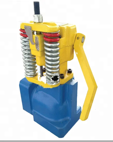
Referring to fig. 1, the embodiment provides a slurry pump relief valve, which includes a valve body 1, the valve body 1 has an inner cavity, a cylindrical pressure relief baffle 2 is integrally formed on the inner wall of the valve body 1, the pressure relief baffle 2 divides the inner cavity of the valve body 1 into a working cavity 3 and a pressure relief cavity 4, a slurry inlet 5 and a slurry outlet 6 are arranged on one side of the working cavity 3 of the valve body 1, and a slurry relief opening 7 is arranged on one side of the pressure relief cavity 4 of the valve body 1;
the center of pressure release baffle 2 is provided with through-hole 8, and 1 inner wall of the valve body of 4 places sides in pressure release chamber is adjacent pressure release baffle 2 is provided with first free bearing 9, pivot articulated have pressure release board 10 on the first free bearing 9, pressure release board 10 hugs closely with pressure release baffle 2, and pressure release baffle 2 is provided with the annular along through-hole 8"s periphery towards a side surface of pressure release board 10, and pressure release board 10 just corresponds the annular to the surface of annular and is provided with annular arch 11, annular arch 11 surface is glued and is covered with annular cushion 12. The one side center that pressure release board 10 deviates from pressure release baffle 2 is provided with the free bearing, rotate on the free bearing and be provided with the pivot, reset spring 13"s one end winding is on pressure release board 10"s free bearing pivot, and reset spring 13"s the other end is the same winding on the free bearing pivot of pressure release chamber 4 place side valve body 1 inner wall, and this reset spring 13 supports pressure release board 10 and supports to lean on pressure release baffle 2 with through-hole 8 inclosed the time, impress annular bulge 11 in the annular, form sealedly.
Therefore, the working principle of the pressure relief valve of the slurry pump provided by the embodiment is as follows: when slurry enters the working cavity 3 from the slurry inlet 5 and flows out from the slurry outlet 6, and when special conditions are met, the pressure in the working cavity 3 is too high, and the pressure acting on the pressure relief plate 10 is larger than the critical value of the spring, the spring is pressed, the pressure relief plate 10 rotates around the pivot on the first hinge seat 9 under the action of the pressure of the slurry, the through hole 8 on the pressure relief baffle plate 2 is opened, and the slurry flows out from the slurry outlet 7 to complete pressure relief.
In addition, the pressure release board 10 still is provided with manual valve, is convenient for at the manual pressure release under the special circumstances, manual valve includes connecting rod 14, pull rod 15 and valve handle 16, the one end of connecting rod 14 is articulated with the one end pivot that pressure release board 10 kept away from first free bearing 9, and the other end of connecting rod 14 is articulated with the one end pivot of pull rod 15, pull rod 15 from pressure release chamber 4 level extend to outside the valve body 1, and set up at the end valve handle 16, pull rod 15 and valve body 1 lateral wall sealing ring 17 sealing connection, it needs to point out that, in this application, the perpendicular distance that connecting rod 14 and pressure release board 10 articulated point to first free bearing 9 is greater than the distance that connecting rod 14 and pull rod 15 articulated mutually are got to first free bearing 9 all the time, like this when outwards pulling during pull rod 15, pull rod 15 can drive pressure release board 10 rotates through connecting rod 14, accomplishes manual pressure release.

Emsco、Gardner-Denver, National oilwell, Ideco, Brewster, Drillmec, Wirth, Ellis, Williams, OPI, Mud King, LEWCO, Halliburton, SPM, Schlumberger, Weatherford
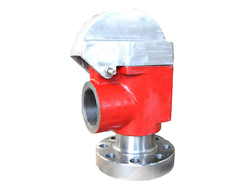
The Model IC valve provides safety for a variety of pressure relief applications including but not limited to: mud, slurry, and fracing fluid relief. The valve relieves pressure to prevent pump, hose and system damage on mud and slurry pump systems – ideal for pulsating pressure. Use instead of nitrogen-assisted valves or ball & spring reset valves where you need greater accuracy and reliability. Our hydraulic fracturing and mud and slurry relief valve ranges are exceedingly popular in the Oil & Gas industry.


 8613371530291