
run mud pump with one geneator and old scr house factory
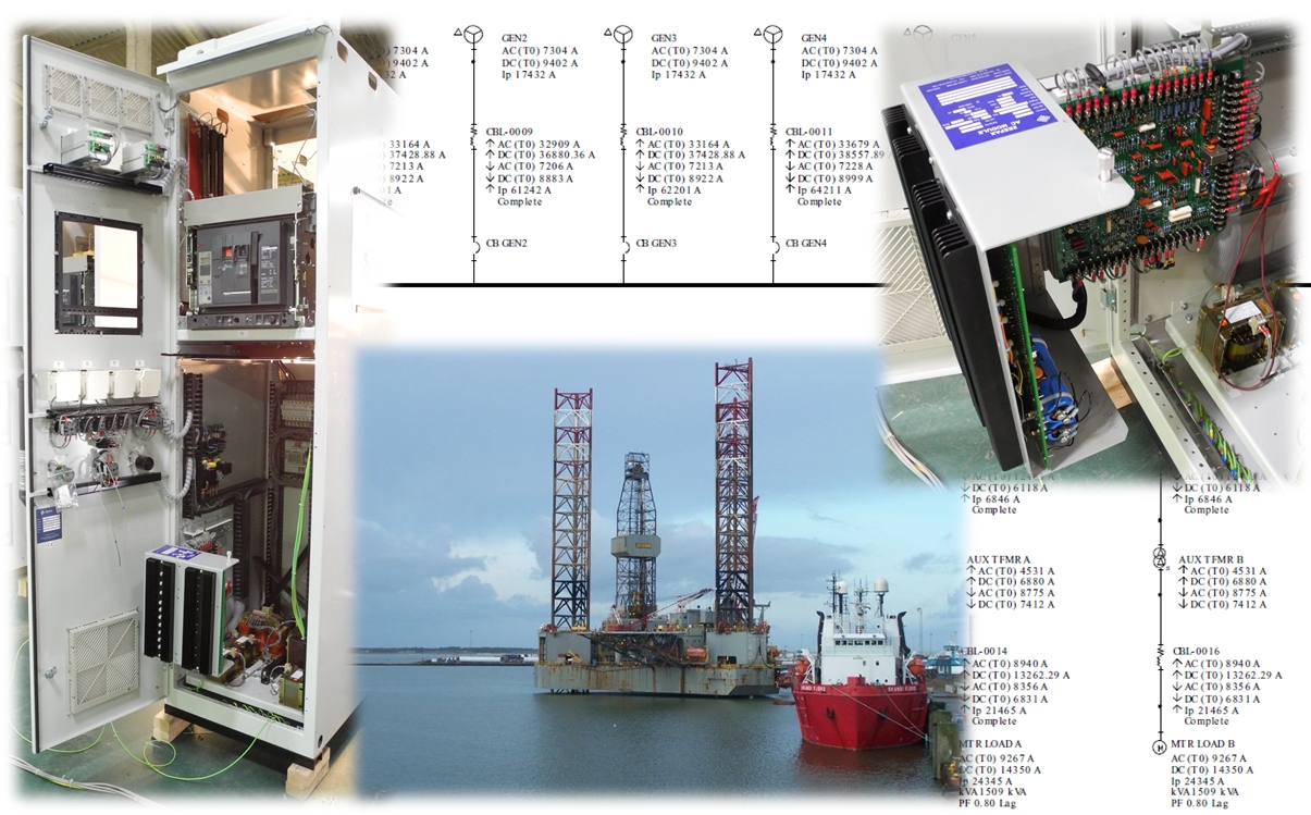
ENSCO 71 is a Jack-Up drilling rig which was originally constructed at the Hitachi Zosen shipyard in 1982. The original GE motor controls comprised five 1163 KVA generators and four 1800 ADC SCR units with associated auxiliary transformer feeders and jacking units. The SCRs were assignable to two 1600 HP twin-motor Mud Pumps, a twin motor 2000 HP Drawworks and a 1000 HP Rotary Table. A separate feeder drives a 1110 HP Top Drive. A fifth SCR was added by Hill Graham Controls in 1985 to power a third 1600 HP Mud Pump, which was cabled to the main busbars.
In early 2012, a decision was made to add a fifth 2500 KVA generator and an additional auxiliary transformer, to close-couple these to the main switchboard via a bus tie circuit breaker, and to include a dedicated feeder for the fifth SCR. A sixth SCR was also included in the switchboard extension to provide an alternative drive source for the third Mud Pump, effectively removing this load from the main switchboard. The switchboard extension, including full integration with the existing GE and Hill Graham equipment, was engineered and built by Zeefax.
As well as providing an extension to the main 600 V switchboard, Zeefax also designed, built and commissioned an accompanying 480 V switchboard comprising of an incoming circuit breaker and a number of small moulded case distribution circuit breakers.
The design and engineering process involved completing a detailed Power Studyto examine the consequences, in terms of fault rating, of adding the new equipment. Various scenarios were considered, and the financial impact was assessed to determine the most cost effective interconnection configuration. As a result of the study the amount of upgrade work required on the existing equipment was minimised.
The Power System Study was completed by gathering data about the existing switchboard arrangement and comparing this to the original, hand written, fault level calculations. The new calculations were performed using software modelling and verified to IEC 61363. The IEC 61363 Short Circuit study represents conditions that may affect typical marine or offshore installations more significantly than land-based systems, including more emphasis on generator and motor decay. This confirmed the original calculations were accurate.
As well as considering the effects of fault currents, Zeefax also completed a complete protective device co-ordination study to confirm and ensure that proper co-ordination was established for all operating scenarios. This included the existing equipment as well as the components in the switchboard extension, and the new 480 V switchboard and transformer.
Finally, the study also included calculating the strength and current-carrying capacity of the busbars under normal and fault conditions to establish the correct busbar sizes and bracing.
Zeefax has developed a program to mitigate against unscheduled stoppages and breakdowns. It is a complete and holistic approach which aims to avoid stoppages but if they do occur, ensure that the resources are on hand to minimise the damage caused. This is the Total Rig Audit (TRA) by Zeefax and is carried out by our very specialised and highly experienced Field Service Engineers.
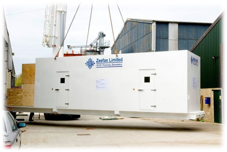
The Zeefax Total Rig Auditavoids downtime and ensures rig systems remain operational and reliable. Many Drilling Companies will invest in a completeRig Auditin the knowledge that it offers a comprehensive overview of the state of their rig, which can also be submitted for compliance and due diligence purposes.SCR Training Simulator
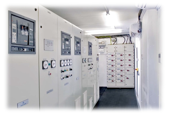
Every Drilling Rig must have a Power Control Room – sometimes also known as an SCR (standing for Silicon Controlled Rectifier) System – which forms the functional heart of the power control of the drilling operations. Typically, SCR systems comprise a large steel room, inside of which will be a range of Motor Control Centres, Engine & Generator Controls, SCR Control cubicles, and other instruments and systems used for drilling purposes.
SCR Systems usually operate at 600V, and clearly, these systems can be extremely dangerous if not operated correctly and carefully by suitably trained operators. It is therefore vital that drilling engineers and operators are well trained using a combination of class room tuition and on-the-job training.
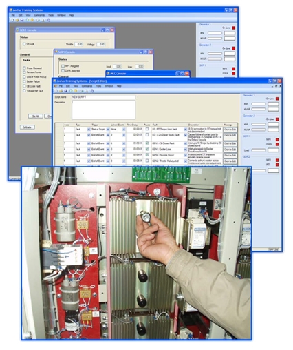
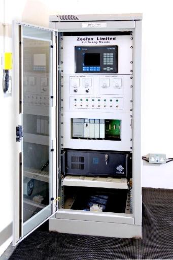
In response to this need, Zeefax have created the world’s first full size SCR Training Simulator, which accurately mimics the a real SCR; it looks and feels like the real thing, providing a realistic experience of live field operations – but without the dangerous high voltage. This system was created specifically for Naftogaz – for more details, click here.
A key feature of the simulator is the addition of the on-board computer system, which mimics all of the signals that would normally come into this SCR system from the live engines and generators, including the motors running the mud pumps, the rotary table or the Drawworks, etc. and can also simulate a wide range of known faults, allowing trainees to experience first hand problem solving in the safety of the simulator, before they experience the live system.GE Legacy Drive Systems
Used the same type SCR bridge as the Generation III, but rated at only 1200-1500 amp since the heat sink assembly is of a slightly different design. This system uses the GE generator GEM modules controls.
1980’s, 900amp. SCR bridges using the GE GEM Generator Control. As the bridges are small it requires two SCR bays to run a two-motor Mud Pump or Drawworks.
This module features digital circuitry providing enhanced control accuracy for speed and voltage, and also provides tools for system diagnostics, including “first fault” and multiple fault storage and annunciation. A fully featured internal diagnostic self-test on power up is provided, and available outputs include system KVA and kW limit protection.
The EGR is a direct replacement for the GEM Module and protects the engine through tachometer loss sensing, over speed detection, and reverse power protection with adjust-able time delay.Test and Calibration Engineer – IMP products
If you are interested in applying for this position, then please send us your latest CV and a covering letter toTest and Calibration Engineer – SCR products
Zeefax is the value source for parts and services for your legacy GE Drive and Generator Control Systems. We hold an inventory of critical spare parts and can provide comprehensive service solutions including Repair and Return of Modules and PCBs.
Zeefax operates a comprehensive repair and return service for all legacy GE Drive and Generator Control Systems. which includes cleaning, testing, repairing or replacement of defective components and a full system load test. This service includes a 6-month limited warranty.
Zeefax understands that replacement of a complete SCR Control System is often not viable due to the large cost and loss of production due to system downtime. At Zeefax we can offer a comprehensive service to support your legacy GE Drives and give it a renewed lease of life. That not only includes supply of spare parts and a repair/calibration service; qualified service engineers with years of experience with these Drives are available for regular Health Checks, fault-finding and general support purposes.Careers
Zeefax Limited has been made aware that unauthorised individuals have masqueraded as Zeefax Limited, promising job opportunities in our name and requesting payments to cover processing fees, visas, work permits or other formalities. The job offers are typically supported by forged documents, giving the appearance of an official communication, including the use of the Zeefax Limited logo and links to the Zeefax Limited website.
Zeefax Limited (nor any of the placement firms that recruit on our behalf) will NEVER require potential candidates to make any form of advance payment as part of the hiring process.
These communications are fraudulent (usually from @worker.com or @126.com) and do not originate from Zeefax Limited (@zeefax.com), nor are they associated with the Zeefax Limited recruiting process. The individuals who are sending these communications are doing so in an attempt to solicit money from potential job seekers. Be cautious of any unsolicited offers of employment particularly if you are requested to supply personal banking information or provide any form of advance payment.
If you suspect fraud, we would urge you NOT to respond to these unsolicited offers of employment, and to report such activity to your local law enforcement agency immediately!
Should you have any concerns over the validity of any correspondence received in respect of employment with Zeefax Limited, contact us directly atPLC Programming
We have expertise in many of the commonly used devices, including Siemens, Allen-Bradley, GE Fanuc and Mitsubishi, and we have the operational experience and knowledge to provide completely new applications or modify existing ones. We are also able to help and advise on strategy and implementation, as well as with start-up and commissioning.
Not only can we provide a comprehensive programming resource to help with your programming needs, we also can provide a series of PLC programming training courses. The comprehensive training experience is intended for those who wish to expand their skills and knowledge of PLC programming, fault finding and maintenance, and include modules for both novice and advanced users.
Course materials include information and techniques for a range of manufacturers including Siemens, Allen-Bradley, GE Fanucand Mitsubishi, and the curriculum may be tailored for specific requirements and needs, but will typically focus on the more practical aspects of Programmable Logic Controller applications.
All of Zeefax’s training courses are held in our design and manufacturing facility, located near London, England. To find out more about our training courses, pleaseDigital AutoSync Module
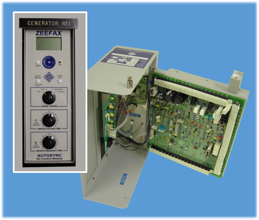
In response to many customer requests, we have designed our own version of the legacy Ross Hill Controls AutoSync AC generator control module; the new module has been completely re-designed and incorporates all new digital circuitry as well as optional expansion capability to future proof the module.
The use of modern digital circuitry and components has resulted in much improved parameter control over the previous legacy module without compromising operational reliability, and the ultra-stable frequency control system ensures safe and accurate control of generation systems.
The new front panel includes the familiar controls, but has been enhanced with the inclusion of an LCD display for module set-up and parameter display purposes; front panel controls include the manual circuit breaker and engine controls, with the addition of digital menu navigation buttons for module set-up and display options.
An important feature of the new modules is that they have exactly the same footprint and connection geometry as the old style legacy modules, making installation and upgrading of the new modules simple and quick.
Wire loom connections and attachment points are identical, meaning that no extra wiring or hardware is required in order to facilitate installation, and the new digital circuitry uses the latest available components and techniques, yielding enhanced reliability and performance over older legacy modules.
Our Research & Development department is currently working on new versions of the traditional AC and DC modules which will be available soon to add to the already released DDC and the Digital AutoSync.
These new modules will provide existing system users with a quick and cost effective upgrade path, maintaining the continuity and availability of well established installations.
Zeefax is an established global supplier of high-quality and reliable electrical and mechanical engineering services. As part of the complete service we provide to the industry, we carry out repair and maintenance of all GE752 Motors, including:
Advancements in technology mean that many of the power semiconductors which were built into SCR systems 30 or more years ago have been superseded by new devices, often with improved specifications.
Our engineers are able to ensure that, when the original component is not available, a suitable replacement can be found. If the replacement is not an exact fit, we can engineer an adaptation to ensure continued serviceability of legacy equipment.Hill Graham Controls (HGC)
Following our acquisition of Hill Graham Controls (HGC), Zeefaxis in a unique position to offer total support for all legacy Hill Graham and Ross Hill Controls (RHC) systems both in the UK and throughout the world.
Zeefax’s unique experience and expertise has allowed the company to design, manufacture, supply, repair and calibrate many of the control modules used within older Hill Graham installations, as well as other manufacturer’s systems, including Ross Hill Controls (RHC) type systems.
In recent times,Zeefax has developed and brought to market a new digital AutoSync module, with an improved contemporary design and operation. This advanced module occupies the exact same footprint and has pin-for-pin connection compatibility with the now obsolete Ross Hill module, thereby providing a simple and cost effective upgrade path for existing users of the AutoSync module.
These services mean that equipment manufactured up to 30 years ago, is still fully supported by Zeefax, and can continue to provide return on investment far beyond the normal life expectancy.Troubleshooting & Maintenance
Zeefax has the experience to assist and provide engineers to troubleshoot issues, help during downtime, and establish a program of scheduled maintenance, targeted and customised for your individual requirements.
As part of our maintenance and service offerings for SCR systems, Zeefax is able to mobilise support and engineers to provide technical assistance during emergency shutdowns and downtime periods.
It is well established that a program of planned maintenance and support can and will ease pressure on people and systems, and can result in increased reliability, uptime and ultimately profitability of the system.
By predicting issues, and by scheduling maintenance, spare parts and manpower can be correctly scheduled, minimising downtime, keeping spare part inventory under control and avoiding unwanted breakdowns.
At Zeefax, we recognise that high-quality and experienced technical resources are required during major works, such as emergency breakdown repairs or un-scheduled downtime.
Given our years of experience and unique position to offer total support for all legacy Hill Graham Controls (HGC), and other manufacturer’s systems including Ross Hill Controls (RHC), IPS, and GE Micro Drill SCR systems, Zeefax can provide a full range of technical services for installation, commissioning, and ongoing operational support.SCR System Health Checks
The time to find out if your system is reliable is when operations are quiet – not during critical well operations – so the Zeefax SCR System Health Check is designed to identify potential weaknesses and either repair or replace immediately, or mitigate against these until a repair or replacement can be effected – usually at a quite time.
Zeefax can help you to perform a comprehensive health check, and propose a detailed scope of work designed to compliment and conform to your operation schedule; this means that any potential disruption is absolutely minimised.
Zeefax understands that each rig or vessel has different circumstances and different requirements. Our engineers are able to tailor a maintenance schedule to suit any installation or operational constraints. Where special equipment is required, such as secondary injection test equipment for testing circuit breakers, Zeefax will arrange to have the equipment on site, and our technician will be competent in its use.
For reliable operation, the contact between the SCR devices and the heatsinks must be as good as possible but over time, and especially in offshore installations, corrosion may attack the interface between the SCR device plating and the aluminium heatsink. If corrosion is present it takes an expert to decide if refurbishment is required because as long as the damage is minimal and the two elements remain undisturbed, the mutual corrosion may still maintain a good contact.
As part of the health check our engineer will do a sample inspection of the heatsinks and recommend a course of action based on experience and knowledge.Repair & Calibration
Since our acquisition of Hill Graham Controls (HGC), our module repair facility and engineers, have been able to test and calibrate modules sent to us for repair within a quick turnaround period. In an important development, Zeefax has designed and built a new AC and DC Module simulator, to provide an improved testing platform for Hill Graham and Ross Hill type AC and DC modules. In particular, the AC module simulator is much improved over the older unit, and provides a greatly enhanced engine control and start-up simulation.
These improvements have been made based on our experience with testing and repairing the modules over many years, and our customers can be confident that any module returned to us for repair will receive the most comprehensive bench test possible.
In addition, we are able to repair and re-calibrate most Hill Graham and Ross Hill type printed circuit boards (PCBs), including Power Limit, Field Supply Regulator, Sprocket Slip, Drillers Console, DC Auxiliary, SCR Auxiliary and Generator Exciter PCBs. Furthermore if following evaluation, repair is not possible, in many cases we can supply new manufactured boards using the original designs, but enhanced by us using modern components and manufacturing techniques. In this way, we can help to ensure that legacy systems remain operational and continue to provide reliable and trouble free service beyond their expected life.Motors & Generators
Even given the relatively controlled working environment of typical SCR pods, the conditions can often cause deterioration to both electrical and mechanical performance, requiring removal of the unit from the system, followed by refurbishment and renovation.
During refurbishment, the pods are disassembled, checked and thoroughly cleaned; resistors and capacitors are replaced, and fuses, actuators and switches are checked and tested for operation, and replaced where necessary, and the pod is fully re-wired.
The heat sinks are inspected and if required, will be re-machined to ensure excellent electrical contact is maintained. Importantly, the SCR Thyristor ‘puck’ is replaced, and very special attention is given to the clamping torque and orientation.
When complete, a full quality inspection and electrical test is performed to ensure that the refurbished cell is in perfect working order prior to dispatch back to the owner.
The severe environment on rigs often leads to a deterioration of both electrical and mechanical performance of Foot Throttles, requiring removal of the unit followed by factory refurbishment and renovation.
Typically, units arrive in poor condition – totally seized and unusable; they are then completely disassembled, thoroughly cleaned and de-scaled, and are fitted with new bearings, bearing blocks, hardware and seals, prior to re-wiring and calibration.
Zeefax is able to provide both factory refurbishment of existing Foot Throttles and in cases where the deterioration is too severe for refurbishment, we can supply a brand new replacement to meet specific requirements.
If you would like to know more about the range of available Driller’s Foot Throttles, please call or email us, and we will be pleased to assist.SCR Blower Assemblies
An important part of every system is the forced air cooling, which is vital to ensure continuity and reliability of operation of the SCR stacks. It is essential that the heat generated during operation is reliably carried away, and Zeefax now produce a series of SCR Blower Assemblies which are compatible with the those used in legacy Hill Graham and Ross Hill type systems.
The Zeefax SCR Blowers are designed to operate with voltages up to 600 V @ 50 or 60 Hz; the operating voltage needs to be specified at the time of purchase (see the details and specification form below) and the blower may be configured with either Single or Duplex impellers and with or without base frames.
In order to aid potential users with the selection of replacement blowers, we have created a simple form which can be used to provide the few technical details we require. In this way, we can ensure that any SCR Blower supplied by us is fully compatible with existing assemblies, and will then install directly into the available location with minimal re-work required. You can download this form from this site; please fill it in and return it to us to receive a quotation.
If you would like to know more about the range of available blowers, please call or email us, and we will be pleased to assist.Printed Circuit Boards (PCBs)
Through our in-house R&D, we are developing improved specification products as replacements for legacy Hill Graham Controls or Ross Hill Controls boards; we can provide original replacements for many of the PCBs used on these systems, and by using modern techniques and components, we can even improve on some of the design features of the original products to enhance reliability and functionality.
This means that equipment manufactured up to 30 years ago is still fully supported by Zeefax, and can continue to provide a return on investment well beyond the normal life expectancy.PLC Training Course Program
During the course, we aim to provide students with an advanced training experience, enhancing the already popular series of PLC training courses provided by Zeefax.
This training course includes modules for both novice and advanced users of PLCs, and includes information and techniques for manufacturers including AB, GE Fanuc, Mitsubishi and Siemens. Courses are intended for both technicians and engineers who wish to expand their skills and knowledge of PLC programming, fault finding and maintenance.
Course programs and content may be tailored for specific requirements and needs, but will typically focus on the more practical aspects of Programmable Logic Controller applications.
At the end of the course, engineers and technicians will be familiar with the program modules and functions, and will be able to fault-find on PLC controlled plants.
The SCR Drive Assignment Contactors are fitted in the armature and are actuated by Allen Bradley PLC logic; through Allen Bradley flex I/O located in the SCR drive bay. The flex I/O communicates through a dual loop Profibus configuration to a processor for the first five SCR bays and a second matching configures for the next five SCR bays. The assignment configuration is such that any motor is assignable in three locations with any motor capable of assigning to the first five SCR bay or the second set of five SCR bays.
Each drive can support 4 different motor parameter sets. All the SCR Drives on the Frontier Driller shall be configured accordingly to the motors that they will support.
This architecture offers flexibility and reliability through redundancy in case of SCR drive failure. Should such an event occur the operator simply turns off the motor on the faulted SCR drive and turns back on allowing the PLC to assign to the next available SCR drive. Each motor is assignable to three different SCR drives with a total of twenty (20) SCR drives in the system.
The SCR Drives are controlled from consoles via profibus loop circuit to the dual redundant Logix 5561 CPU Allen Bradley PLC system. Overview of the SCR distribution with SCR PLC.
By use of the dual 5561 Allen Bradley processor (CPU) in the PLC system either processor can fail with no loss of operation. Communications to the drives is done by Profibus loop directly to the Siemens 6RA70 and flex I/0 locate each SCR bay. The flex I/O receives input and from devices outside the drive such as armature contactor feedback, drive cooling fan overload, circuit breaker status and the OFF/DRILL/MARINE selector switch. The flex I/0 receives output commands outside of the 6RA70 control for contactor assignments. The Siemens 6RA70 SCR drive sends and receives data as per the supplied manual, which controls operation of the motor and gathers operating information for logic control. All control signals from SCR to PLC shall be communicated through PROFIBUS DP field bus protocol, with the exception of the Emergency Stops, which shall be hardwired directly to the SCR Drive breaker for safety.
Signals exchanged between an SCR and its respective PLC are the same for each SCR. Apart from standard control/status signals, signals related to assignment and power management need to be exchanged.
This architecture offers flexibility and reliability through redundancy in case of PLC or communication failure. Should such an event occur, the communication cable could with stand one break in any loop and complete failure of either PLC1-A or PLC1-B with no loss of operation.
There is a PROFIBUS DP communication network for each SCR drive to the two PLC racks located in the generator cubicles. Each network is completely independent from the other with communications that are loop and able to be controlled by either CPU. The PLC racks located in the Driller’s Console and in the Mud Pump Console are networked by Ethernet Fiber optic loop to a MOXA module to convert the fiber signal. The two screens in the driller’s console are networked on this same loop with both screens able to display the same screens and status. There are two more MOXA modules connected in the same loop to supply data to the two workstations to enable data collection and trouble shooting of the complete system. There are two more MOXA modules on the same loop connected to PLC3A and PLC3B in the field supply cabinets, which in turn are connected to all the MCC, by Profibus fiber optic loop for control and status of all the required motor starters. Overview of the SCR PLC PROFIBUS DP and Ethernet communication network.
The PROFIBUS DP network in this application is based on 3 different mediums and topologies. A standard bus or line topology network with standard PROFIBUS DP RS-485 cable is established between an SCR PLC and its respective SCR drives. Each SCR is fitted with a CBP2 PROFIBUS communication board. Each one has its own address to differentiate between the various SCR Drives on the network. A redundant optical ring topology is established between all PLC racks via MOXA hub modules to form the Ethernet network. The third communication loop is Profibus fiber optic to all the Hirschmann Hub modules in the MCCs and the same type loop collecting data from the generator controls. MOXA modules and Hirschmann hub modules convert electrical signals to optical signals.
As of July 2007 we have completed the manufacturing portion of this project and have started testing the communications of the 5 remaining SCR Drive bays along with the Generator bays, Driller’s Console, Mud Pump Console & SCADA System. We have already shiped 5 DC drive bays and 1 of the 2 Isolation Switch bays and will ship the remaining equipment after completion of testing and DNV approvals.
Modern drilling techniques require additional equipment not found on older drilling rigs. Existing power systems can be modified by Advanced Control Systems in the field to accommodate the addition of Top Drives, Generators, Mud Pumps, and Independent Rotary Tables.
Obsolete SCR / Engine-Generator Control Systems can be economically retrofitted, refurbished or replaced altogether to increase dependability and decrease downtime.
By using this site, you are agreeing to security monitoring and auditing. For security purposes, and to ensure that the public service remains available to users, this government computer system employs programs to monitor network traffic to identify unauthorized attempts to upload or change information or to otherwise cause damage, including attempts to deny service to users.
Unauthorized attempts to upload information and/or change information on any portion of this site are strictly prohibited and are subject to prosecution under the Computer Fraud and Abuse Act of 1986 and the National Information Infrastructure Protection Act of 1996 (see Title 18 U.S.C. §§ 1001 and 1030).
If a user or application submits more than 10 requests per second, further requests from the IP address(es) may be limited for a brief period. Once the rate of requests has dropped below the threshold for 10 minutes, the user may resume accessing content on SEC.gov. This SEC practice is designed to limit excessive automated searches on SEC.gov and is not intended or expected to impact individuals browsing the SEC.gov website.
Our DC systems are based on an industry standard design and inherit the dependability, reliability and ease of maintenance of this concept. Our AC systems are built around ABB drive and control technology. Enhanced systems, PLC control and serial links to the Drill Floor are available to reduce rig-uptime for land rigs.
We also have the expertise to source replacements for obsolete spare parts, and re-engineer older systems with new equipment, including adding extra SCR sections for third Mud Pumps or Top Drives, and additional generator sections for additional rig power.
We are able to provide training either on-site using your existing equipment, or from our base in London, England. As well as providing in-depth knowledge and support for SCR and generator control systems.
As to the electric system, we compared the DC drive rigs and AC converterdrive rigs deeply, we recommend AC (AC-VFD-AC)converter drive rigs due to the following advantage of AC Converter drive rigs.
2, It has the limitation function of Torque and rotation speed, strong overload protection could avoid the broken of drill pipes and other main parts.
Being a manufacturer of power generation controls and high power electronic variable speed driveequipment, Joton must maintain qualified personnel to ensure our products are put into service correctly, and effectively. The wide range of specially designed power equipment sold, designed and manufactured by Joton means that our startup and service personnel must be versatile in the full scope of their knowledge.
This can be of great benefit to customers that have not purchased any of our manufactured products. Our technical staff has knowledge in the following areas and can provide technical Oilfield service in these areas if you have equipment that is shut down from an unresolved failure, or just need to ensure the system is operating correctly.
We’ve been in a flurry of activity this year, crushing out upgrades on over thirty rigs selected for our 2017 Rig Upgrade Program. Most recently, our team in Nisku, Alberta cut the tape on the new-and-improved Rig 44, which was upgraded from a 750 HP SCR to a 1,000 HP AC-powered heavy telescopic double.
Proudly boasting “first-of-its-kind” status in our Canadian fleet, the rig and its crews were turned loose in the Montney Basin for the first time this week since the upgrade.
The combination of Rig 44’s high hook load, AC-power, 1,600 HP direct-drive mud pumps, and 7,500 PSI circulating system make it unique to our Canadian fleet. It’s also equipped with bi-fuel engines and a walking system capable of moving the rig with full setback (meaning the drill pipe is left in the derrick during the move).
Want to see more of our 2017 upgrades in action? Check out Trinidad Rig 100, the first ever rig in our US fleet, with its new 1,000,000 lb. hook load, walking system, 25,000 foot racking system with 5 inch drill pipe, and 7,500 PSI capabilities.
I’ve run into several instances of insufficient suction stabilization on rigs where a “standpipe” is installed off the suction manifold. The thought behind this design was to create a gas-over-fluid column for the reciprocating pump and eliminate cavitation.
When the standpipe is installed on the suction manifold’s deadhead side, there’s little opportunity to get fluid into all the cylinders to prevent cavitation. Also, the reciprocating pump and charge pump are not isolated.
The gas over fluid internal systems has limitations too. The standpipe loses compression due to gas being consumed by the drilling fluid. In the absence of gas, the standpipe becomes virtually defunct because gravity (14.7 psi) is the only force driving the cylinders’ fluid. Also, gas is rarely replenished or charged in the standpipe.
Installing a suction stabilizer from the suction manifold port supports the manifold’s capacity to pull adequate fluid and eliminates the chance of manifold fluid deficiency, which ultimately prevents cavitation.
Another benefit of installing a suction stabilizer is eliminating the negative energies in fluids caused by the water hammer effect from valves quickly closing and opening.
The suction stabilizer’s compressible feature is designed to absorb the negative energies and promote smooth fluid flow. As a result, pump isolation is achieved between the charge pump and the reciprocating pump.
The isolation eliminates pump chatter, and because the reciprocating pump’s negative energies never reach the charge pump, the pump’s expendable life is extended.
Investing in suction stabilizers will ensure your pumps operate consistently and efficiently. They can also prevent most challenges related to pressure surges or pulsations in the most difficult piping environments.
• The Power Control Room (SCR House) will be Top Lift Only, and be equipped with roof mounted handrails and an access ladder mounted on the outside (just as the original)
• Includes power and control provisions for an Eddy Brake (Baylor Brake) to include an MCC feed, and internal cables. Our proposal does not include the actual Brake Controller or the transformers.
• The standard electronic engine/generator controller uses a 0-200 mA signal to control the engines direct fuel rack and thus its engine speed. If necessary, a 4-20 mA engine speed signal conversion kit is available for engines that cannot use the 0-200 mA signal.
• All power and control cable terminations are intended to be “hard-wired” through ROX frames. No plug boards will be used. Will include the ROX frames only.
4- Model 1500 I-DRIVE SCR Drive Cubicles each equipped with electronic controllers, primary and secondary assignments, and 600V feeder circuit breaker switches
4 - Generator Control Cubicles each equipped with electronic controllers (metering module, governor module, and voltage regulator module) and 600V feeder circuit breaker
E. One (1) Low Voltage Distribution and Lighting Distribution Panel with 3- pole, 2-pole, and 1-pole breakers as required (will match the existing unit but may be relocated to a new location in the house.
F. One (1) Power Control Room outdoor, weatherproof, insulated, mobile steel building equipped for Top Lifting Provisions. The building will contain the above wired and tested equipment.
* KW/KVA limiting circuitry monitors the available power and compares it against the KW/KVA in use, so that the power consumed by the SCR system does not exceed the available power on the line.
* Control power will be 120 VAC for best contact integrity and line noise immunity. The system will be provided with a control power transformer to provide control for standard contactor logic and alarm function. Each SCR converter section will be assignable to two (2) loads. Assignment switching will provide 100% redundancy in case of converter or load failure.
* All logic functions will be provided according to customer specifications and necessary safety functions. There will be two (2) SPST load interrupting main contactors for each assignment.
5) I-Drive module is a standard unit; interchangeable on any system, on shore/off-shore, single motor, two motor operation and series or shunt motors.
I-Drive Power Limiting protects the diesel engine/generator set(s) from dropping "Off Line" due to an overloading. When maximum KW or KVA capacity has been reached, the system "phases back" the outputs of the SCR drives connected to the AC Buss, and thus prevents the generator sets from dropping off line due to an overload.
The I-Drive SCR Control Module accepts four different current limit settings, which corresponds to the four possible assignments of the SCR drive. The I-Drive SCR DC cardrack test panel has four potentiometers where the Current Limits are set. The current limit settings are a separate module from the D/C module which allows changing the D/C module without resetting current limits.
The I-Drive Firing Circuit Regulator works in conjunction with the AC Buss Phase Sensing and the Six Gating Pulse circuits. The SCR firing pulses are referenced to the Three AC Lines, and timed to trigger the respective SCR"s at the correct instant.
There are six firing pulses (each spaced 60 degrees from the previous) in each cycle and all are adjusted simultaneously by the firing enable circuit to get the correct SCR firing angle.
This feature allows the I-Drive SCR drive to deliver more current for a short period of time than what is preset with the current limit Calibration as set on the DC cardrack test panel. This feature can be used in situations where high current is needed for short periods of time, I.E. for a drawworks motor. The amount of overcurrent allowed is set at the Timed-Overcurrent Module, from 110% to 130% of the present current limit for approximately 60 seconds. After the 60 seconds period, the current will revert to the normal current limit as set at on the I-Drive DC cardrack test panel so as not to damage or overheat the SCR bridge.
1. Over-temperature: When the SCR Blower is lost or the SCR house internal ambient temperature rises to an unacceptable level so that proper cooling of the SCR’s is not possible, a set of thermo-switches, mounted on the SCR bridge heatsinks detect when the temperature goes above 70 degrees C and signals an alarm condition
2. Blown Fuse: The SCR bridge has a set of semi¬conductor fuses for the protection of the SCR"s. If any of the fuses open, the FFAS (fuse failure alarm signal) is activated (isolated contact closure) and the firing pulses to the SCR bridge are automatically inhibited
All the controls ARE interlocked. If the bay is re-assigned during power on, the bays shut down and will not restart until their respective throttles have been returned to the ZERO (off) position. This includes the foot throttle.
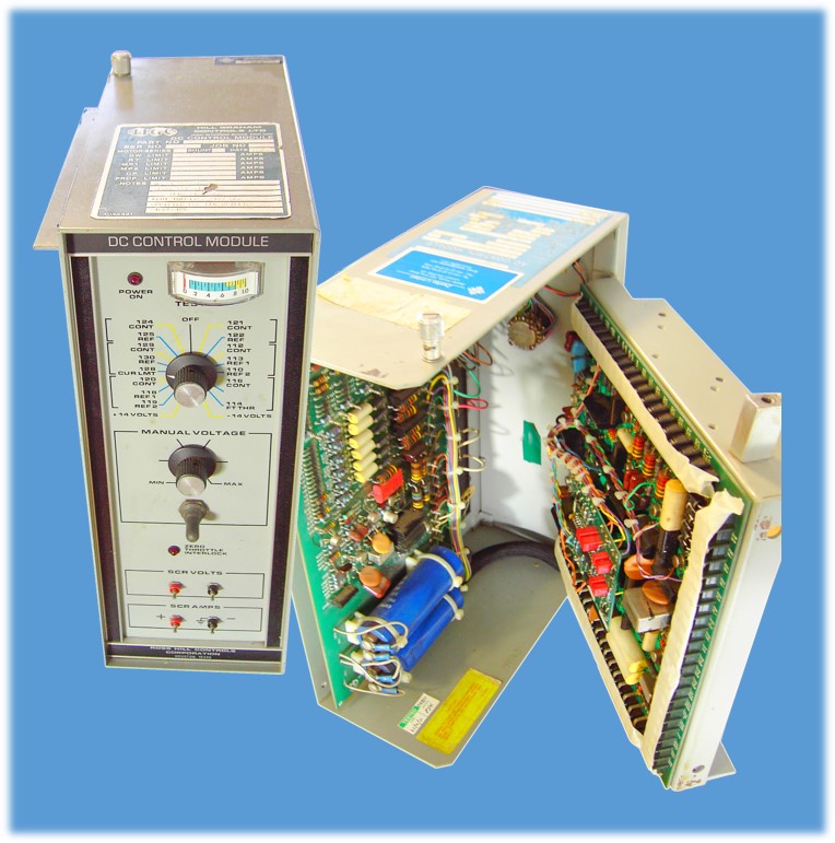
The I-Drive SCR drive is of modular design, compact, NEMA type 1 A construction WITH DRIPSHIELDS, front access only. The D.C. control module contains the circuitry necessary to control the SCR Bridge’s output. The module is interchangeable between all I-Drive SCR systems. The module is furnished with no adjustments necessary. The module is easily disconnected for replacement should the need arise. This makes for a minimum of “down-time” should a failure occur.
The I-Drive SCR Bay cooling is assisted by a squirrel cage blower forcing air in the direction from bottom to top of the cabinet. Air is drawn in through a filter in the lower section of the front door. It then proceeds over the contactors, DC buss, and into the blower intake. The blower’s output airflow goes directly into the plenum below the SCR bridge, into the bridge heatsinks (the point of the most air flow resistance), out the top of the bridge, upward past the circuit breaker and AC buss, and out the top of the cabinet.
The I-Drive SCR Bridge is composed of three (3) identical and interchangeable modules (Phase Cells). Each Phase Cell has an AC input flag, a minus DC output flag, and a plus DC output flag. In the Phase Cells the discrete SCR devices have heatsinks on both sides. Thermodynamics proves that this allows the SCR devices to operate at a lower temperature than single sided “bricks” for the same device current. The lower the operating temperature, the more reliable the SCR device is. The system is designed for low maintenance and to operate in ambient air temperature up to 50 degrees C without air conditioning.
The I-Drive drawworks dynamic brake will slow the drawworks motors from full speed within eight to ten seconds after the foot throttle is released. The power of the free wheeling motor is fed back into a resistor bank. During normal operation the dynamic brake system is non-operative, and the drawworks is either OFF or operating at the desired cathead speed. If however, at any time the motor speed is higher than the DW throttle speed setting, and the foot throttle is OFF, the dynamic brake system is actuated, reducing the motor speed to the DW throttle setting.
The I-Drive foot throttle is constructed of rugged stainless steel throughout; built to withstand the environment normally encountered on the rig floor.
The I-Drive Drillers Console will be NEMA type 4X construction of #316 stainless steel1 outdoor weather proof and provided with air purge/pressurization fittings to allow use in a Class 1, Division 2 hazardous area. All assignment switches, hand throttles and controls will be front mounted on the door. All meters, instruments and annunciators will be mounted behind the front door with a safety glass view window provided to view the meters and instruments, etc. The door will be attached with stainless steel hinges and positive latching stainless steel latches.
One set of I-Drive generator control cubicles consisting of three (3) each I- DRIVE model 1200 engine/generator control modules, breakers and related equipment for the control of three (3) each engine/generator sets and a synchronizing and ground detection cubicle.
I-Drive AC Electronic Control Section contains the AC cardrack. Three modules plug into the AC cardrack. They are the Engine Electronic Governor module, Generator Electronic Voltage Regulator module and the Metering control module. All external connections to the AC cardrack are by barrier strip (screw type).
Dynamic KW load sharing - each regulator is independent and automatically shares when placed “on line” KW sharing can be set to track within 2% of rated KW of generator.
Dynamic KVAR sharing - each regulator is independent and automatically shares when placed “on line” KVAR sharing can be set to track within 2% of rated KVAR of generator.
The HOCC System will supply power for the engine starting circuit and the pulse pick-up circuit in each generator control module. The system/operation will consist of the following.
1 – Set of Hands off cranking batteries consisting of gell cell batteries and electronically regulated battery chargers to provide cold start power for engine controls.
1 –Engine control power supply (each generator control section) to provide engine control power to each engine. Upon initial start up (cold) the batteries will supply cold power to the engine controls to allow engine starting. After the generators are online, the engine control power supply will provide control power for continuous operation. After the engine control power supply is activated, the batteries will drop out and revert to stand-by power in case of primary power supply failure.
2 Each - 800AF/800AT circuit breakers, DRAWOUT MONTED each to feed power to one (1) 1000 KVA 600/480V power transformer and interlocked so that only one can be closed at one time
Motor Control Center will be NEMA Type lA Construction, front access only with horizontal and vertical solid copper bus. Motor starters to be motor starter/circuit breaker combination type full voltage, non-reversing with 3 pole overload blocks, overload heaters, control power transformer, fuses, operating handle, and start/stop push button (or H-O-A Control) in the door.
The horizontal buss will be copper and suitably rated. The vertical buss will be will be copper and rated for 300 amps. A copper round buss will run the full length of the MCC Line-up.
The columns and ceiling framing will be constructed from structural steel. The outside steel sheeting will be fabricated from sheet steel, min. 12 ga.
The walls and roof sheeting sections will be welded together. The floor will be fabricated from three sixteenth inch thick smooth steel plate. The inside surface of the walls will be finished with a sandwich style insulating board, three eights inch thick with white pebble coating in the interior. The ceiling will be formed from inverted Tee-Bar and lay-in insulated ceiling board.
Two (2) industrial steel doors are provided on the sides with "Anti-Panic" handles for quick, easy opening. Doors open outward. Doors can be locked from the outside but can be opened from the inside even when locked.
Standard 48-inch fluorescent lights, a battery operated emergency light activated by loss of power on generator main bus, and convenience outlets for customer use will be provided.
Two (2) 7.5-Ton Self-contained air conditioning units that will maintain the inside temperatures within the design limits of the installed electrical equipment are included. The air conditioning will be supplied by a total of two units. Either unit will maintain operating temperature limits with one for a back-up. These air conditioning units will be fed from the A/C MCC. AC units will be installed on the roof.
The exterior of the building will be cleaned with a sweep blast of sand to remove scale and oxidation. The exterior coating will consist of a sub-coat of zinc rich primer, and covered with a coat of polyurethane, color white. The interior floor of the building will be covered with black colored epoxy enamel. The skid base will be primed and painted black.
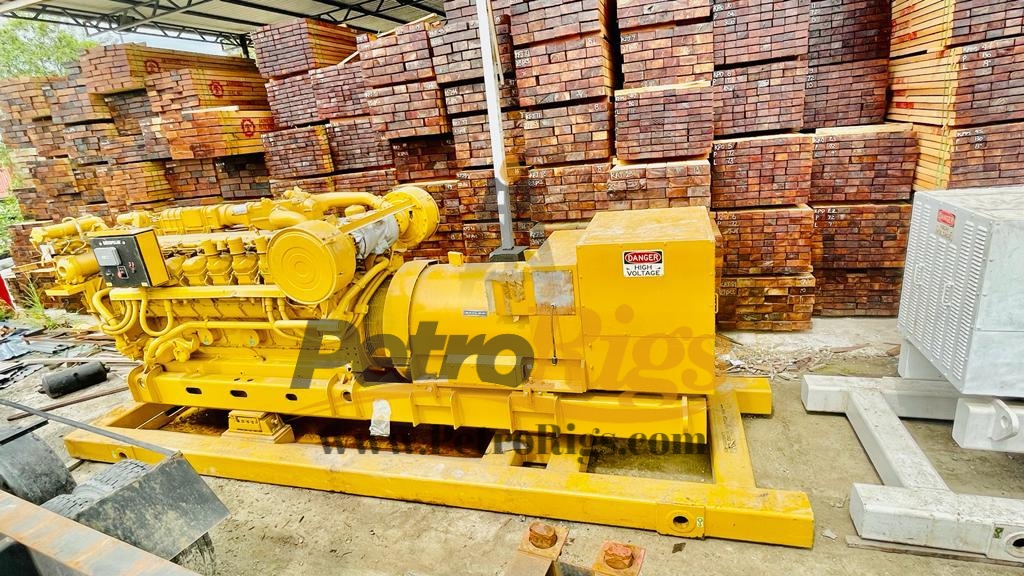
NOTE - Includes one Caterpillar 12-cylinder, direct-injected, turbocharged, aftercooled diesel oilfield engine; 4 cycle, 170 mm bore x 191 mm stroke (6.7 in bore x 7.5 in stroke) with separate-circuit after- cooler and optimized for low emissions. Engine rotation is standard (counter-clockwise as viewed from flywheel end).
COOLING SYSTEM - In order to ensure compliance in use, optional or customer-supplied radiators must be capable of rejecting enough heat to allow proper operation at worst case site conditions, and also must supply 122 deg F (50 deg C) SCAC cooling water to the aftercooler inlet, with an SCAC flow rate of at least 100 GPM (379 l/m) with an ambient temperature of 86 deg F (30 deg C) and at-site conditions (including altitude considerations). Maximum allowable SCAC flow rate is 115 GPM (435 l/m). RADIATOR COOLED LAND BASED: Outlet controlled thermostat and housing. Jacket water pump, gear driven. Dual outlets: 88.9 mm O.D. (3.5 in) elbow hose connections. Aftercooler fresh water cooling pump (SCAC), gear driven centrifugal SCAC pump circuit contains a thermostat to keep the aftercooler coolant from falling below 30 deg C (85 F).
EXHAUST SYSTEM - Exhaust outlet: 292 mm I.D. (11.5 in). 12-10.5 mm dia holes EQ SP, 376 mm bolt hole dia. Shipped loose: Exhaust flexible fitting: 318 I.D. mm (12.5 in) 12-14 mm dia. holes EQ SP, 375 mm bolt hole dia. 306.6 mm tall with compressed gasket. Exhaust adapter: 297 mm I.D. to 340 mm I.D. (11.7 in to 13.4 in). 12-10.5 mm dia. holes EQ SP, 376 mm bolt hole dia. 12-13.8 mm dia. holes EQ SP, 430 mm bolt hole dia. 158.5 mm tall with compressed gasket. Weldable flange: 360 mm I.D. (14.2 in). 12-13.8 mm dia. holes EQ SP, 430 mm bolt hole dia. 17.4 mm wide with compressed gasket. Exhaust manifolds, dry. Dual turbochargers with w/c bearings.
INSTRUMENTATION - Electronic instrument panel, LH. Analog gauges with digital display data for: Engine oil pressure gauge. Engine water temperature gauge. Fuel pressure gauge. System DC voltage gauge. Air inlet restriction gauge. Exhaust temperature (prior to turbochargers) gauge. Fuel filter differential pressure gauge. Oil filter differential pressure gauge. Service meter (digital display only). Tachometer (digital display only). Instantaneous fuel consumption (digital display only). Total fuel consumed (digital display only). Engine start-stop (off, auto start, manual start, cooldown timer).
PROTECTION SYSTEM - ADEM A3 ECM monitoring system provides engine de-ration, or shutdown strategies to protect against adverse operating conditions. Selected parameters are customer-programmable. Status available on engine- mounted instrument panel and can be broadcast through the optional customer communications module or programmable relay control module(s). Initially set as follows: Safety shutoff protection, electrical: Oil pressure, water temperature, overspeed, crankcase pressure, aftercooler temperature. Includes air inlet shutoff, activated on overspeed or emergency stop. Alarms, electrical: ECM voltage, oil pressure, water temperature (low and high), overspeed, crankcase pressure, aftercooler temperature, low water level (sensor is optional attachment), air inlet restriction, exhaust stack temperature, filter differential pressure (oil and fuel). Derate, electrical: High water temperature, crankcase pressure, aftercooler temperature, air inlet restriction, altitude, exhaust temperature. Emergency stop push button, located on instrument panel. Alarm switches (oil pressure and water temperature), for connection to customer-supplied alarm panel. Unwired.
SMEC has been instrumental in giving support for new built/retrofit/replacement of SCR House/SCR System for various customers in Oil & gas sectors. Our acquired technical expertise and extended & solution specific manufacturing facilities are used in providing complete turnkey SCR packages and solutions for drilling rigs and platforms. State-of-the-art control systems developed by us are based on the established and well proven technology and designs with respect to modern hybrid / digital technology
In accordance with the instructions received by Century Resources, two surveyors attended Century Rig 14 in Cirebon Indonesia to complete a Rig Condition Survey. The aim of the survey was to determine the present condition of the Drilling Package and associated equipment ensuring the equipment was fit for the intended purpose and in a safe operating condition. Included in the above scope was the following: • Carryout the inspection of the equipment to the criteria of the checklist supplied by Century Resources. The audit was conducted in good faith and without prejudice. 1.3
The inspection criteria, which have been used as reference during this inspection, are the owner’s safety and operating standards, the original equipment manufacturers maintenance and operating specifications and accepted oilfield operating and safety practices.
RIS Surveyors attended Century Rig 14 in Cirebon Indonesia to complete a Rig Condition and Safety Survey. An inspection work scope had been determined by correspondence with the Maintenance Manager prior to mobilization to the rig. A subsequent meeting was held on site with the Rig Manager and the attending surveyors to discuss and coordinate the work scope of the inspection. The aim was to assist personnel with forward planning and to prepare documentation and the equipment for inspection. At the time of inspection, the rig was being packed for shipment and was not operational which allowed very good access to most equipment for intrusive inspections. Given that a substantial amount of the equipment was not able to be operated, it was not possible to test some of the safety devices or carryout any functional checks on most of the equipment. Should this be requirement by either Century or their client then a subsequent visit would be required when the rig was in a fully operational state. This would involve the RIS surveyor to be in attendance for the close out and acceptance of the rig. If all recommendations and planned maintenance repair procedures are followed and a suitable reactivation period be allowed, then it would be fair to state that the rig could be expected to operate in a safe and continuous manner on a drilling program. Drilling Equipment An intrusive inspection was carried out on the National 80-UE draw works which was found to be in an acceptable condition. Bearing lift checks were conducted on the main drive shaft, jack shaft and drum shaft, these were all found to be within the manufacturer’s acceptable limits, there was no functional testing of this unit whilst we were on site. The rotary table was visually inspected, the gear backlash 0.043” which is acceptable. The master and split bushings were found to be in poor condition, dimensional checks were conducted and exceeded manufacturer’s specifications for wear limits. The Ideco 500T Swivel was visually inspected; the Quill stem length was measured and was only 10” long. It would be recommended to have a spare Quill available. There were no NDT records available on location for neither the travelling block nor the hook assembly. Documentation is reported to be in the Jakarta office however if not available NDT inspection should be conducted prior to the rig commencing the new contract. On the block, one side door was opened to access the sheaves, bearing side movement checks were conducted and found acceptable, the sheaves were gauged with only minimal wear noticed and found to be in good condition. The latch and lock for the hook lever were functioned and working as they should.
Drilling Mast The drilling mast was visually inspected and there was no obvious damage noticed to the structure, all main supports and diagonal braces were found to be in good condition. There were no recent NDT reports available for the mast or substructure however a third party Inspection Company is currently on location and in the process of conducting NDT on all critical areas of the mast. The NDT was 80% completed during our inspection with no defects found at that time. The crown sheaves were rotated and side movement checks conducted on bearings, minimal movement only was detected and found to be in good condition, the line grooves on all sheaves were gauged and checked for wear. Only slight wear was detected however well within the API recommendations. A rubber type bumper block is fitted to the underside of the crown and well secured, all padeyes in the crown section were noted to be numbered and a pad-eye register was available, currently all pad-eyes are being inspected by third party and once completed will require colour coding with the current colour for this six monthly period. The racking board was checked, all fingers were straight, handrails acceptable, the main frame and pad-eyes need to be NDT inspected and is in the current work scope for the NDT. Due to the sections of mast and substructure being stacked it was not possible to locate the mast compliance plates to confirm load ratings. The rig floor personnel elevator was visually inspected. Further inspection will be required once it is rigged up on location. All pipes handling equipment was inspected, documentation was not available on location to show previous NDT inspections, generally the elevators and slips were found to be in good condition. The Iron roughneck is currently waiting on parts to repair the hydraulic motor on the pipe spinner. Substructure The substructure was visually inspected and due to being packed for mobilization it was not possible to get 100% access to all areas, NDT inspections have been conducted on all critical areas with no defects found at the time of our visit, all accessible sections of the substructure that were inspected were found to be in acceptable condition. The raising system appeared to be in good condition, all sheaves were gauged and bearing checks conducted the raising lines and bridal line were visually inspected and found to be acceptable. No function checks were conducted on the Lantec Winches. Electrical Equipment Due to the mobilisation of the rig, one air compressor was the only electrical equipment that was operational at the time. Extensive checks were performed on the electrical aspect of the Mud pumps, Draw works and camp generators. It was agreed that the Drilling generators would not be inspected due to the planned change out of these Engine /Generator packages. Unfortunately the SCR house was packed and secured for shipping so further checks should be performed on this equipment after Rig arrives on location and electrical system is energised for
drilling operation. Checks still outstanding and should be completed prior to start up are as follows. • Full function test of engine shut downs. • Under voltage, over and under frequency and reverse power trip tests. • Inspection of all MCC and SCR modules. • Inspection of generator power limit function (if system installed) • Drilling instrumentation checks. • Rig PA function test. • Complete lighting inspection. • Hazardous area electrical equipment inspection. • Re-inspection of electrical Generators and DC motors that had very low insulation readings recorded as per below report. Mechanical Equipment As previously mentioned, it was not possible to run function tests on most of the equipments; however we did manage to run one MCC generator 480 V to supply temporary power to the office, no ESDs or safety systems were functioning as tested on the rig. Both air hoists were visually inspected and have line and drum covers fitted, SWL is visible, and line spoolers are fitted to both winches. The mechanism for disengaging the drum has been removed and the system is locked into the engaged position to prevent free-wheeling of the drum, and complies with safety requirements as detailed in OEM safety alerts. No function tests have been conducted. The Ingersoll-Rand Man Rider winch was not connected and no function test conducted this is an approved dedicated man riding device and complies as per manufacturers spec. The air package consists of four compressors, 2 x Sullair, 1 x Champion and 1 x Cold start. The 2 Sullair series10 air compressors were visually inspected, only number one was operational during the inspection. Isolation valves, instrumentation and pressure relief valves have been checked. The cold start with Sullair compressor was inspected and operated; the Un-loader system was checked and functioned as it should. Mud Systems The mud tank system was inspected and found to have some areas with corrosion, the internal coatings of the tanks have deteriorated in areas causing corrosion pitting and may require some welding repairs, and work is currently in progress to descale these areas to further assess the condition. The low pressure lines appeared to be in good condition, it would be recommended that UT thickness checks be conducted to assess the overall condition of the tanks and pipe work for preventative maintenance purpose. The standpipe and mud lines were visually inspected and appear to be in fair condition. No documentation was available on location for previous UT inspections, the wall thickness checks need to be conducted periodically to assess the integrity of the pipe for safe working pressure ratings. Reports also need to be kept for any modifications of sections that have been welded into line which should include NDT radiography proof pressure tests for the high pressure system. Report Title: Century Rig 14
The three DFE shakers were inspected and were found to have been poorly transported; two of the shakers have not been secured to the beds causing some damage to the electrics and screen tensioners. The repairs were completed during the inspection and were found to be acceptable. Mud pumps The three National 9-P-100 Mud Pumps, 2 x electric and 1 x driven by Cat D399, underwent an intrusive inspection and were found to be in acceptable condition with no major faults noted. Bearing lift checks were conducted on all pinion, crank and eccentric bearings, the crosshead clearances checked, all readings taken are within the manufacturers recommended tolerances. A check of the back lash between the Bull Gear and the Drive pinion was taken and this was found to be within the manufacturer’s specifications. Well Control The Shaffer single was opened and inspected, ram blocks rubbers and seals were found to be in good condition. Cavity measurements were acceptable and within tolerances. No pressure test or function tests were conducted. Ring grooves were well protected and in good condition. On the double , the upper rams were opened and required cleaning, it appears that they were not properly flushed on the previous job leaving a large amount of cement in the cavity and around ram blocks, cleaning was completed and measurements taken and found to be acceptable. The lower doors were opened and were found to be in similar condition. No documentation for the BOP was available on location; we have been informed that this is available in Jakarta office. Current certification should be provided and full low and high pressure tests should be conducted to ensure that the equipment is in a safe operating condition. The Hydril MSP 2000 20” Annular was visually inspected, the element / ring grooves appeared to be in good condition, the 4 lifting eyes were noted to have been NDT inspected however one of the eyes is badly damaged. The Choke manifold was checked and all valves were free and easy to open / close, one valve was removed for internal inspection and found to be in acceptable condition. No pressure test charts were available for previous tests; we have been informed that the previous tests were only conducted to 1200 psi. A full pressure test program should be undertaken which should include both low and high pressures tests from both sides to the SWP of the respective sides of the choke manifold. The Accumulator was not connected during the inspection and no function test conducted, the unit has three banks of six bottles, these banks can be isolated individually and bled back to the reservoir, it was noted that there was a low pressure alarm fitted, the alarms was not functioned. A full accumulator drawdown test should be conducted when the BOP’s are rigged up to ensure that the unit has sufficient residual


 8613371530291