
sj 300 mud pump in stock

Used SJ Petro SJ-300 Triplex Mud Pump. 300hp Hydraulic Power or 350 Max Input hp. Ser# 0609279, 5" Plungers x 5" Stroke. Steel Block Fluid End. 4.31:1 Gear Ratio. Comes with Detroit 6V71 Turbo Diesel engine. 7 Valve Manifold with Roper Charge Pump. Roughneck Heater, Fuel Tank, Hydraulic Oil Tank, Air Tank, Parts Storage, Lights, Flow Control & Manual Transmission.

Pump Parts - SJ PETRO SJ-300 TRIPLEX MUD PUMP, Pumps & Parts, Used SJ Petro Model SJ-300 Triplex Mud Pump. 5" Metal Plungers x 5" Stroke. Steel Block Fluid End, 4.32:1 Internal Gear R... More Info
Pump Parts - SJ PETRO SJ-300 TRIPLEX MUD PUMP, Pumps & Parts, Used SJ Petro SJ-300 Triplex Mud Pump. 300hp Hydraulic Power or 350 Max Input hp. Ser# 0609279, 5" Plungers x 5" Stroke. ... More Info

SJ300 horizontal single acting triplex plunger pump widely used for cementing, fracturing and circulating operations consists of PG power end and fluid end. PG05 power end has a steel housing. 5", 4-1/2", 4” and 3-3/4"plungers are provided for different cementing requirements.

Other Industrial Pumps└ Pumps & Pump Accessories└ Hydraulics, Pneumatics, Pumps & Plumbing└ Business & IndustrialAll CategoriesAntiquesArtBabyBooks & MagazinesBusiness & IndustrialCameras & PhotoCell Phones & AccessoriesClothing, Shoes & AccessoriesCoins & Paper MoneyCollectiblesComputers/Tablets & NetworkingConsumer ElectronicsCraftsDolls & BearsMovies & TVEntertainment MemorabiliaGift Cards & CouponsHealth & BeautyHome & GardenJewelry & WatchesMusicMusical Instruments & GearPet SuppliesPottery & GlassReal EstateSpecialty ServicesSporting GoodsSports Mem, Cards & Fan ShopStampsTickets & ExperiencesToys & HobbiesTravelVideo Games & ConsolesEverything Else
Rig pump output, normally in volume per stroke, of mud pumps on the rig is one of important figures that we really need to know because we will use pump out put figures to calculate many parameters such as bottom up strokes, wash out depth, tracking drilling fluid, etc. In this post, you will learn how to calculate pump out put for triplex pump and duplex pump in bothOilfield and Metric Unit.

The 2,200-hp mud pump for offshore applications is a single-acting reciprocating triplex mud pump designed for high fluid flow rates, even at low operating speeds, and with a long stroke design. These features reduce the number of load reversals in critical components and increase the life of fluid end parts.
The pump’s critical components are strategically placed to make maintenance and inspection far easier and safer. The two-piece, quick-release piston rod lets you remove the piston without disturbing the liner, minimizing downtime when you’re replacing fluid parts.

Table of contentsSection I. General DescriptionSJ600S Pump DescriptionSJ600S Pump Performance Parameters/Installation DrawingInstallation for LH gear boxInstallation for RH gear boxTach Drive/Rate Meter Calibration SpecificationUseful Data FormulaShipping and Storage
Section II. Installation DetailsPump Installation HighlightsPower End Lube System RequirementsPower End Lube System CartogramRecommended Power End Lube OilPower End Lube Startup and Performance DataPlunger Lube System RequirementsRecommended Plunger Lube OilPressurizing System RequirementsPressurizing System Operation Parameters
Section III. Pump Operation and MaintenanceSJ600S Pump Start-up and shut-down ProcedureRecommended Pump Sealing MethodsTrouble-Shooting GuideRoutine Preventive MaintenanceFluid End Repair ProceduresPower End Repair ProceduresTorque Table
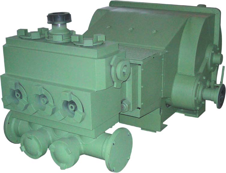
Section I. General InformationSJ600S Pump DescriptionThe SJ600S is a reciprocating, positive displacement, horizontal single-acting, triplexplunger pump which is rated at 600 Brake Horsepower input maximum. The SJ600Sis designed for intermittent duty well service applications such as acidizing,cementing, fracturing, well killing, gravel packing, etc.The SJ600S Pump consists of a Power End, Speed Reducer Assembly and a Fluid EndAssembly. The Speed Reducer can be installed on either the right hand or left handside of the pump and can be installed in any one of 17 different input shaft locationsto accommodate a number of different pumping unit drive train configurations. Twodifferent fluid cylinders are available to accommodate several plunger sizes for avariety of pressures and volumes. Optional packing assemblies, valve assemblies,discharge flanges, suction manifolds, etc. are available for a wide variety ofunitization arrangements; for the pumping of various specific fluids; and for service ina wide range of ambient conditions. The weight of the pump will vary slightlydepending on plunger size and other options but will not vary more than plus or minus5% of the advertised weight.The basic design and structure features of SJ600S plunger pump is as following:A. Power End DesignPart description
Long lasting coil springs engineered for a wide range of well serviceapplications. Designed for spring rates, installed spring loads, and valvecracking pressures unique to well service pumps.
SJ600S is a kind of single acting pump. Make sure the crankshaft rotates at the lower limit ofmaximum connection rod angle. The rotating direction of crankshaft is always from lubrication oiltube to rear pump. See the above drawing.
Note: the volumetric efficiency and resulting displacement will vary slightly due tooperational factors such as pump speed, supercharge conditions, and thespecific gravity of the fluid being pumped.V.E.
Useful Data FormulasA. Symbol Definition:A-------------------------- Area (sq. in.)BHP ---------------------- Brake horsepowerBPM---------------------- Barrels per minute (U.S.)FV------------------------- Flow velocity (ft./sec.) AGPM---------------------- Gallons per minute (U.S.)GPR----------------------- Gallons per revolution (U.S.)HHP ---------------------- Hydraulic horsepowerID-------------------------- Inside diameter (inches)ME------------------------- Mechanical efficiencyNC--------------------------Number of cylinders (per pump)PD------------------------- Plunger diameter (inches)PSI------------------------- Lbs./sq. in.RL-------------------------- Rod load (lbs.)RPM------------------------Crankshaft revolutions per minuteSL-------------------------- Stroke length (inches)T---------------------------- Torque (ft. lbs.)B. Pump Data Formulas:1. When the flowrate and pressure is given, you can get the HHP:GPM PSI= HHP17142.
All the pumps should be shipped under dry condition, and must be flushed andfilled with the proper lubricant before operation (see section II). Pumps may beflushed with diesel or light oil. When pumps are shipped by ocean cargo, careshould be taken to create the pump in a watertight container and ship below deckto prevent salt water contamination.
New pumps are not prepared for long periods of storage and should be put inservice as soon as possible. To prepare a pump for storage after prior use, cleanthe fluid end and flush it with good rust preventive. Plug all fluid end dischargeand suction openings. Drain oil from power end, thoroughly clean and flush withgood rust preventive which will not clog oil passage. Remove crankcase breatherand plug all openings. Coat the pinion extensions and pony rods with a heavy rustpreventive. Store pump inside in a warm, dry place.
Pumps which have sat idle for any appreciable period of time (two weeks or more)must have the plungers and valves removed, coated with a light lubricant andreinstalled prior to operating. The rubber plunger packing and valve inserts willstick to the matching metal parts and become damaged upon startup if notdisassembled and lubricated first.
Section II. Installation DetailsPump Installation HighlightsThe proper installation of your SJ600S pump is a must in obtaining long life andtrouble free service. Particular attention must be given to the following item:A. Power SourceThe prime mover (usually a 2100 RPM diesel engine) should not be rated at morethan 725 BHP (intermittent services) in order to avoid overpowering the pumpB. Power drive chainThe drive chain which connects the pump to the engine should include atransmission (5 speed or more) and mechanical driveline with universal joints anda slip joint in order to fully utilize the pumps wide range of pressure and flowcapabilities.A power shift type transmission with integral torque converter and automaticlock-up clutch will provide the most trouble-free means of shifting under pressure.When using an ordinary mechanical transmission with manual clutch, extremecaution must be exercised when clutching and shifting in order to avoidintroducing severe shock loads to the pumps input shaft. When using anytransmission with a high gear or overdrive ratio greater than 1.0:1, theoverdrive gear range must be blocked out in order to avoid over-speeding thepump. When using a transmission with a torque converter and/or a low gear ratioof 5.0:1 or lower, extreme caution should be exercised to avoid over-pressuringthe pump when operating in low gear or converter mode.The mechanical driveline should have a Diesel Engine Use torque rating ofapproximate 1250 to 1700 ft. lbs. (6500 to 8900 ft. lbs. Short duration) andshould have no less than 1 slip capacity. The manufacturers recommendationsfor maximum installed angle, maximum RPM, etc. must not be exceeded.C. Power End Installation:- 14 -
The pump must be securely bolted to the skid or vehicle at all four power endmounting hold locations (refer to pump installation drawing).D. Power End LubricationSJ600S well service plunger pump are shipped dry, do not include an integral oilpump, and are designed for a pressure lubricated dry sump system. An auxiliaryoil reservoir and engine driven oil pump must be provided for proper lubrication.More information pertaining to the power end lube system and power end lubeoils is included in this manual.E. Plunger LubricationSJ600S well service plunger pumps require a force fed oil plunger lube system.More information pertaining to the plunger lube system and plunger lube oils isincluded in this manual.F. Supercharging SystemSJ600S well service plunger pump require the use of a centrifugal slurry pumpsupercharging system. More information pertaining to the superchargingrequirements is included in this manual.
Power End Lube System RequirementsProviding a well designed trouble-free power end lube system is one of the mostimportant factors in obtaining maximum service and long life from the SJ600S wellservice plunger pump. Due to the nature of well servicing operations, the highestpump pressures and highest load conditions occur at very slow pump speeds. Thischaracteristic of well service pump operation necessitates the use of an engine drivenlube pump which will deliver maximum lube oil volume at high engine speedsregardless of slow pump speeds. As a result of this operating characteristic and themany different equipment design possibilities, it is not feasible for SJ600S to providea power end lube system with the pump. The equipment manufacturer who builds thepowered well service unit must provide power end lube system components which arecompatible with the specific engine, transmission, etc. being utilized on the unit.A properly designed power end lube system will meet the followingspecifications:1.
A. Must be of 50 gallon minimum capacity.B. Suction outlet to be 1 1/2 minimum and located as deep as possible.C. Suction outlet and return inlets to be as far apart as possible.D. Return fitting for drain back to be 3 minimum; return fitting for relief valveline to be 1 minimum.E. A serviceable magnet located near the 3 return port is highly recommended.F. Breather/filler cap to be 40 micron/25 CFM minimum and should include abuilt-in strainer to prevent trash from entering the reservoir.G. Dipstick or sight glass to indicate oil level in the reservoir.H. Reservoir must be located below the lowest drain port in the plunger pumpand as near the plunger pump as possible (preferably directly underneath).2.
(400-150 micron) wire cloth, 300 sq. in minimum element area, 3 to 5 PSI (6to 10 Hg) built-in bypass, and rated at 50 GPM minimum flow. An in-linecanister type strainer is much preferred due to the ease of routinemaintenance is cleaning the element.C. A 1 1/2 minimum swing type check valve may be used in the suction line ifthe lube pump is located above the fluid level in the reservoir.D. The suction line should be as short as possible, should be free from excessivebends, and should be wire reinforced to prevent collapsing. If longer than 10ft. the resulting friction losses should be compensated for by increasing theline size to 2 I.D. minimum.3.
Lube pump:A. Must be a gear type pump rated at 12 GPM minimum at its installedmaximum RPM.B. Inlet and outlet ports should be as large as possible w/1 1/2 inlet and 3/4outlet preferred.Note: If the gear pump suction inlet port is smaller than 1 1/2, a swageconnection should be used on the suction port in order to maintain a 1 1/2suction line size as near the gear pump as possible.C. A liquid filled vacuum gauge (0 to 30 Hg) should be installed as near thegear pump suction port as possible in order to monitor the suction flowcondition, especially during cold startups in cold weather.D. The gear pump may be direct coupled to an accessory drive location on theengine or can be direct coupled to the transmission with a pump-mount typepower take-off (PTO). The transmission/PTO mount usually offers theadvantage of a lower mounting and improved suction conditions. The lubepump mounting must be a direct coupled positive drive arrangement whichoperates at engine speed whenever the plunger pumps prime mover isrunning.
of 800 PSI.C. The oil filter must be rated at 50 GPM/200 PSI minimum, must have abuilt-in 15 to 25 PSI relief valve, and 25 to 33 micron elements. The filtermay be of either the spin-on throw-away element type or the canisterenclosed throw-away element type. The filter must be located in an easilyserviceable location and a built-in bypass indicator (service indicator) isrecommended. A dual element filter rated at more than 50 GPM will decreasethe pressure drop associated with filtering 90 weight gear oil and willincrease the time interval required between filter element changes. Anexternal relief valve should never be used to protect the filter.D. A liquid filled 0 to 200 PSI oil pressure gauge must be located at the 1/2NPT lube inlet on the plunger pump. An auxiliary oil pressure gauge is alsohighly recommended for those units having remote control console.5 Lube system relief valve and relief return line:A. The system relief valve should be a 3/4 20 to 25 GPM, 60 PSIminimum/200 maximum, adjustable non-chattering type relief valve.B. The relief valve must be located at the plunger pumps 1/2 NPT lube port(opposite the lube inlet) to insure oil flow throughout the plunger pumpbefore reaching the relief valve.C. Te relief return line should be 3/4 I.D. minimum, wire reinforced, rated at800 PSI minimum operating pressure; and should be return directly to thereservoir.6 Lube drain lines (from plunger pump to reservoir):A. SJ600S is equipped with a 2 NPT drain port in the speed reducer housingand a 3 NPT drain port in the bottom of the power end housing. The drainlines should never be smaller than the drain port in the power end/speedreducer and should be as short as possible. The drain lines should be free ofexcessive bends and kinks and should flow continuously downhill to thereservoir. If necessary, the 2 drain line from the speed reducer can be teedinto a common 3 drain line returning to the reservoir. The lowest 2NPTdrain port in the speed reducer should always be utilized for the drain line inorder to prevent the speed reducer from accumulating excess oil.
B. A 0 to 250 F oil temperature gauge should be installed in the primary drainline such that its sensor will be submerged in the return oil from the plungerpump. The temperature gauge should also be located in a place easilyaccessible for viewing. An auxiliary oil temperature gauge is also highlyrecommended for those units which have a remote control console.7 Optional lube system equipment:A. In extremely hot ambient conditions, an oil cooler may be required to preventexcessive oil temperatures and inadequate oil viscosity. When used, the oilcooler should be of the air to oil or forced air type and should be locateddown-stream from the oil filter. The cooler should be rated at 50 GPM/250PSI minimum, and should have 3/4 minimum inlet and outlet connections.If the well service unit will also be subjected to periods of cold weather, theoil cooler must be plumbed in a manner that will allow the oil bypass thecooler when cold ambient conditions occur.B. In extremely cold ambient conditions, the use of either an electronic sumpheater or a tube and shell heat exchange may be required to preventextremely poor lube suction conditions, lube pump damage, and plungerpump damage due to the lube oil becoming too cold and viscous to flowproperly. When used, the electronic sump heater should be installed near thesuction outlet in the oil reservoir and should be capable of heating the oil toapproximately 80 to 100 degrees Fahrenheit over an 8 to 12 hour period oftime. The sump heater must be thermostat controlled to prevent overheatingthe oil. When using a tube and shell type heat exchange for lube oil heatingwith engine jacket water, the heat exchanger should be rated at 50 GPM/250PSI (minimum) with 3/4 minimum inlet and outlet oil passage connections.The heat exchanger must be plumbed in a manner that will allow it to beeasily bypassed in the event the power end lube oil temperature starts toexceed 180 degrees Fahrenheit.Note: Upon request, SJPETRO can provide lube system components which meetor exceed the specifications noted herein. Please contact SJ Engineering Dept. forany further information pertaining to your specific pump lubricationrequirements.
Recommended Power End Lube OilsSelecting the proper gear oil for satisfactory power end lubrication is very importantto obtaining long life and trouble-free service from the high performance SJ600Splunger pump. SJPETRO highly recommends the use of one of the modern syntheticgear lubricants which are now available through all major lubricant markets. Syntheticlubricants exhibit a much more stable viscosity over a wide range of ambientconditions. Synthetics also offer a much improved film strength compared to aconventional gear oil of the same viscosity. The use of synthetic gear lubricants willimprove lubricant flow at pump startup, will provide superior wear protection, andwill result in higher hydraulic horsepower output due to reduced drag and frictionbetween mating parts.1.
These gear oils must be rated for extreme pressure (EP) service, must have aviscosity index of 135 or higher, must have a pour point of 35 degree F or lower,must have a Timken Test rating of 50 lbs. or higher, and must have a viscosity of125 SUS or higher at 210 degrees F. The operating temperature of plunger pump mustnot exceed 180 when using one of these gear oil. Some examples of the variousbrands of synthetic gear lubricants, which offer extended power end protection, are asfollow:AmocoSynthetic gear lubricants 75W-90BPTransgear S 80W-140ChevronTegra Syngear 75W-90CitgoSynthetic Gear Lubriciant 75W-90ConocoSyncon 75W-90ExxonSGO 75W-90MobilMobilube SHC 75W-90PennzoilSuper Maxol S#220Petro-CananaSyngear E 75W-90EPPhilips 66Philguard 75W-90ShellSpiraxS 75W-90TexacoSyn-star EP220- 21 -
Conventional non-synthetic gear oil may be used in SJ600S plunger pump; howevermore care must be taken in selecting the proper grade of oil to use for the prevailingambient conditions during a given season of the year. In all cases, a conventional gearlubricant must contain an extreme pressure (EP) additive, must meet or exceed U.S.Mil-Spec.Mil-L-2105B, and must have a Timken Test rating of 45 lbs. or higher.Following is a list of the various brands and grades of conventional gear lubricantswhich may be used seasonally as indicated:A. Alternate moderate service (for spring and fall ):These gear oils are suited for use in moderate ambient temperatures whichrange from 32 degrees F to 90 degrees F. These oils must have a pour pointof 0 degrees F or lower and must have a viscosity of 85 SUS or greater at210 degree F. the plunger pumps operating temperature must not exceed 175degrees F when using one of these oils:Amoco90-grade Multiusage gear lubricantsBPTransgear 85W-140ChevronUltra gear lubricants #220CitgoPremium gear lubricants (MP) 80W-90ConocoIndustrial gear lubricants #220ExxonEsso Gear lubricants GX 80W-90MobilMobilube HD 80W-90Philips 66Multiusage gear lubricants with high quality 80W-140ShellSpirax HD 80W-90TexacoMultigear EP 80W-90B. Alternate high temperature service (for summer or tropical climates):These gear oils are suited for use in moderate ambient temperatures whichrange from 40 degrees F to 110 degrees F. These oils must have a pourpoint of 20 degrees F or lower and must have a viscosity of 125 SUS orgreater at 210 degree F. the plunger pumps operating temperature must notexceed 195 degrees F when using one of these oils:
AmocoMultiusage gear lubricants 85W-140BP-Transgear 85W-140ChevronUltra gear lubricants 85W-140CitgoPremium gear lubricants (MP) 85W-140Conoco-Universal gear lubricants 85W-140ExxonEsso gear lubricants GX 85W-140MobiMobilube HD 85W-140Philips 66- Multiusage gear lubricants with high quality 85W-140Shell--Spirax HD 85W-140Texaco-Multigear EP 85W-140C. Alternate low temperature service (for winter):SJPETRO highly recommends the use of a resultant pressure gear oils toany plunger pump under frigid atmosphere. These gear oils are suited for usein low temperature service which range from -15 degrees F to 70 degrees F.These oils must have a pour point of -20 degrees F or lower and must havea viscosity of 75 SUS or greater at 210 degree F. the plunger pumpsoperating temperature must not exceed 130 degrees F when using one ofthese oils:AmocoMultiusage gear lubricants 80W-90BP-Transgear 80W-90ChevronUltra gear lubricants 80W-90CitgoPremium gear lubricants (MP) 80W-90Conoco-Univers Special Esso gear lubricants GX 75W-90MobilMobilube HD Plus 75W-90Philips 66- Multiusage gear lubricants with high quality 80W-90Shell-Spirax HD 80W-90Texaco-Multigear EP 80W-90
Power End Lube Startup and Performance DataA properly designed lube system should require adjustments to the system onlyonce---at the well service units original startup. Following are SJ recommendedguidelines for making the initial adjustments as well as the lube systems operatingspecifications:1.
Initial Lube System Adjustments And Specifications:A. Fill the power end lube oil reservoir with the proper grade of EP gear oil forthe existing ambient conditions. Do not over-fill the reservoir--- the properoil level should always leave approximately 10% air space above the fluidlevel. For example, only 45 gallons of oil should be used in a reservoir whichhas a 100% internal capacity of 50 gallons. Disconnect the lube oil suctionhose at the lube oil suction inlet and fill the hose w/gear oil to prime the lubepump. Reinstall and tightened the suction hose.B. With the plunger pumps transmission in neutral, start the engine and run atidle only. It will take a few minutes to pump oil through the entire systemcompletely filling all lines, filters, etc. during which time a thorough checkshould be made for oil leaks at hose connections, etc. after all the lines arefilled, the system should begin to show pressure on the gauge at the systemof air. Kill the engine and add oil to the reservoir in order to bring it back tothe full level.C. With the transmission in neutral, restart the engine. Rev the engine up to fullRPM gradually while checking both the vacuum gauge at the lube pumpsuction inlet and the pressure gauge at the plunger pump lube inlet. If thelube oil is warm enough and thin enough, the vacuum reading will notexceed 10 Hg. The oil will eventually warm up just from the friction oftraveling through the lube system and through the plunger pump.When the vacuum reading no longer exceeds 10 Hg at full engine RPM,adjust the lube system relief valve so that the lube pressure does not exceedapproximately 150 to 175 PSI at full engine RPM.- 24 -
Note: The oil filter is usually the lowest pressure rated component in the lube system.The system relief valve setting is made primarily to protect the oil filter and can be ahigher setting than 175 PSI as long as it does not exceed the lowest rated componentin the system. The plunger pump itself will not be damaged unless the oil pressureexceeds approximately 400 PSI.Again, check the entire lube system for leaks, kill the engine, and add oil to thereservoir if necessary. The plunger pump should not be rotated until the plunger lubesystem is installed and operating properly.2.
Power end lube system readings will vary considerably due to the extreme viscositychanges in the gear oil as it warms and thins from a cold startup till it reaches fulloperating temperature. The system pressure and vacuum variations are caused by theextreme viscosity changes in the oil. The type SEA90wt. Gear oil even at roomtemperature is very viscous (much likes molasses), creates much resistance to flow inthe system, and creates high system pressures even at very low lube flow rates.Likewise, the typical SAE 90wt. gear oil at 150F to 175F becomes much less viscous,flows very freely, and creates much less resistance in the system showing up asconsiderably lower system pressures.Due to the extreme viscosity changes in the gear oil and due to the many differentpossible system designs, it is difficult to establish a firm set of system readings whichwill be highly accurate for every system. Each system will vary somewhat especiallyin the area of stabilized temperature and pressure readings during full horsepower orfull torque plunger pump operation. The system specifications herein should beobserved in addition to each units normal system characteristics after having been putinto service.Maximum Acceptable Vacuum ReadingAt Lube Pump Suction Inlet at Any Time:While Operating the SJ600S Plunger Pump------------------------------10 inch mercurycolumnMaximum Oil Pressure at Cold Startup and Full Engine RPM--------175PSI- 25 -
Maximum Oil Temperature at Any Time:While Operating the SJ600S Plunger Pump:With General Service SEA 90 Gear Oils ----------------------------- 175FWith Cold Weather SEA 80 Gear Oils--------------------------------- 130FWith Hot Weather SEA 140 Gear Oils--------------------------------- 195FApproximate Normal Oil Pressure at Stabilized Operating Temperature and FullEngine RPM ------------------------------------------------------------------------------- 70100PSIWhile Operating the Plunger Pump at Full Engine RPM:Minimum Oil Pressure at Any Time and stabilized Working Temperature---------40PSINote: Any sudden vacuum, pressure or temperature deviations from normal(especially if accompanied by any usual noise, vibration or smoke) indicate the needto cease pumping operations and investigate the problems before power end damageoccurs. (See trouble shooting section of this manual)
Plunger Pump System RequirementsSJ600S well service plunger pumps are designed for packing lubrication with oilrather than grease. Exceptionally long packing life can be excepted providing properlubrication is supplied to the plunger packing lube port above each stuffing box.Ample plunger and packing lubrication can be achieved with an inexpensiverelatively trouble-free low-pressure air operated lubricant pump type system.Mechanically driven plunger lubricators are not recommended due to the well servicepumps extreme variations in pump speeds. A properly designed packing lube systemwill meet the following specifications:1.
Oil reservoir:A. Should be of approximately 5-gallon capacity.B. Should be equipped for the vertical installation of an air-operated pump.C. Should be equipped with a dipstick or sight glass.D. Should be equipped with a breather/filler cap that has a built-in strainer toprevent trash from entering the reservoir.
Air operated lubricant pump:A. Vertical air operated 12 oz. per minute/150 PSI/40:1 ratio lubricant pump.B. Must be equipped with a 1/4 adjustable air pressure regulator in order toadjust the pump speed and packing lubricant flow rate.C. Should be installed so that the bottom of the pump is no closer than 1 to thebottom of the reservoir.
In-line relief valve:It is critical that an in-line relief valve be included in the circuit when plungerwiper rings are used with the packing. Otherwise, excessive lube pressure willdamage the wiper.A. Should be having a cracking pressure of 32 PSI.B. Must be installed in-line between the lubricant pump and the plunger pump.C. Should be equipped with a pressure gauge between the relief valve andlubricant pump.D. A return line should be connected from the relief valve to the oil reservoir so- 27 -
Packing lubricant flow lines:A. Should be 1/4 I.D./1250 PSI minimum/fiber or wire reinforced hose toprevent crimping.B. Should be a common line from the lubricant pump to the plunger pump atwhich point it will branch off to each individual packing lube port.
Speed control valve:A. Should be a 1/4 speed control valve, which can be locked at any givensetting after adjustment.B. Must be installed in each lubricant flow line which leads to the individualpacking lube ports in the plunger pump fluid cylinder.
High pressure check valve:A. Must be rated at or above the well service plunger pumps maximumpressure rating.B. Must be installed in the packing lube port so that the direction of flow is intothe fluid cylinder.
Packing lube system flow requirements/adjustments:After filling with the proper grade of packing lubricant rock drill oil, and beforerotating the well service plunger pump, the line leading to each plunger portshould be bled-off at the connection leading into each check valve.A. Packing without wiper ring:The lube system should be adjusted so that oil drops rapidly from the packingnut at each plunger. The flow should then be adjusted so that the drips occuronly once every second. Each plunger and packing assembly requiresapproximately 437ml per hour in order to be properly lubricated.B. Packing with wiper ring:All pumps (with a rod wiper) require a 30psi limit to the plunger lubricationsystem. Adjust the lube relief to 30psi maximum. Exceeding 30psi may causepremature failure of the wiper ring.
Recommended Plunger Lube OilsSelecting the proper plunger lube oil is very important to obtaining long life from thepumps plungers and packing assemblies. The use of a superior plunger lubricant willalso reduce horsepower robbing friction, reduce fuel consumption, and increase thenet amount of hydraulic horsepower delivered by the pump. SJPETRO highlyrecommends the use of a modern cutting tool oil for improved lubrication of theplungers and packing. In an area where this kind of oil is not available, suitable oilmay be substituted. The following lubricating oils are recommended to use underdifferent ambient temperature:1. Common operation--- the ambient temperature is always above 32F:AmocoWaytac lubricating oil #220BP-Energol SW #220-CChevronVistac lubricating oil #220XCitgoSlideRite 220Conoco-HD Way lubricating oil #220ExxonEsso Febis220MobilVactra 4# lubricating oilPhilips 66-Philips Way lubricating oil #220ShellTonna V lubricating oil #220Texaco-Way lubricating oil #2202. Low temperature operation--- the ambient temperature is always below 32F:AmocoWaytac lubricating oil #68BP-Energol SW #68-CChevronVistac lubricating oil #68XCitgoSlideRite 68Conoco-HD Way lubricating oil #68ExxonEsso Febis68MobilVactra 2# lubricating oilPhilips 66-Rock Drill lubricating oil EP #80870ShellTonna V lubricating oil #68Texaco-Way lubricating oil #68- 30 -
Note:A. If not use the lubricating oil above or the oil with big differences, the servicelife of the plunger and packing will be shortened, and some components will befailed untimely.B. Proper lubrication is critical during the startup of the plunger pump. Theplunger lubricant must begin to flow freely to the stuffing box lube inlet prior tothe pumps startup and stroking of the plungers.C. Pumps which have sat idle for any appreciable period of time (two weeks ormore) must have the plunger removed, be coated with plunger lube oil, andreinstalled prior to operation under power. The rubber packing rings willeventually stick to the plunger surface and will become damaged upon startup ifnot re-lubricated as noted above. Although conditions will vary, onlyapproximately one pint of lubricant per hour per plunger is required for adequatelubrication. A minimum of 20 drops of oil per minute per plunger is required.When using an SJPETRO air operated plunger lube system, the audible sound ofthe air operated lubricant pump stroking once every one to two seconds will beindicator of satisfactory plunger and packing lubrication.D. For all style of packing, the plunger lube is absolutely critical for goodpacking and plunger life. Failure to provide adequate or appropriate lube willcause the packing to fail and cause damage to mating components.SJPETRO recommended the use of ROCK BIT or WAY OIL that meets thefollowing specifications:ISO Grade
Lubricants that fail to meet these specifications, and especially used crankcaseoils are unacceptable.Startup is a critical time for plunger packing. Lubrication should flow freely toplunger prior to stroking the pump. Although conditions will vary, generallytwenty drops per minute lube oil rate is recommended. Stroking dry plungers cancause the header ring and packing to tear and fail.
Supercharging system requirementsDue to the high speed design characteristic associated with well service plungerpumps, supercharging the SJ600S is a must. The nature of well service operations(extreme variations in flow rates coupled with the pumping of heavy slurries) requiresa well designed supercharge system. The supercharging system must deliver anadequate supply of liquid to the plunger pumps suction manifold at high enoughpressures and low enough flow velocities high enough to keep solids suspended in thefluid slurry. A well designed supercharging system is extremely important in avoidingthe harmful effects of cavitations and insuring trouble-free service from the SJ600S. Awell designed supercharging system will meet the following guidelines.1. Main Suction Piping and Hoses:There are defined as the piping where the fluid first begins to flow from its sourcethrough gravity flow or atmospheric pressure only. This portion of the system isusually a pipe or hose which connects the fluid reservoir to the charge pump or insome cases to a mixing pump. The flow velocity based on the plunger pumpsmaximum flow rating with the size plunger being used in this portion of the systemmust not exceed 4 ft. per second in order to flow freely under atmospheric pressure orgravity flow. Other guidelines are as follows:A. The hoses must be oil and chemical resistant wire reinforced combinationvacuum/discharge hose rated at 30 Hg/60 PSI minimum.B. If steel piping is used, all piping runs must be installed so that they are levelor progressively higher toward the plunger pump in order to prevent air trapsin the system. When used, reducer fitting should be of the eccentric type andinstalled belly down in order to prevent air traps. All welded connectionsmust be air and fluid tight.C. All piping or hoses in this portion of the system should be kept as short aspossible (10 ft. or less) and should be free of excessive bends and turns.2. Centrifugal Supercharge Pump/Mixing Pump:Some well servicing operations require the use of two centrifugals one for mixingslurry and the other for supercharging the plunger pump. When two centrifugals areused, they must both meet the following guidelines:- 33 -
A. Must be capable of delivering the rated maximum flow of the plunger pumpwhile maintaining 30 PSI (69 ft. head) at the plunger pump suction inlet.B. Must be sized appropriately to overcome any friction losses in the pipingbetween the centrifuges discharge and the plunger pumps suction inlet. Forexample, depending on the length and the layout of the piping, thecentrifugal may have to be sized to deliver the required flow at 50 PSI (115 ft.head) at its discharge in order to maintain 30 PSI (69 ft. head) at the plungerpump suction inlet.C. Must be operated at a speed which will deliver the requires flow within theupper 15% of its efficient range in order to assure adequate fluid accelerationon demand from the plunger pump.D. Must be adequately powered to deliver the plunger pumps fluidrequirements based on volume, pressure and specific gravity of the fluid orslurry.3. Secondary Suction Piping and Hoses:These are defined as the piping which carries fluid under pressure from the centrifugalpumps discharge to another point in the system. This is the piping which connects thecentrifugal charge pump to the plunger pump suction inlet and can also be the pipingwhich connects the centrifugal mixing pumps discharge to a mixing tub inlet. Theflow velocity in this portion of the system (based on the plunger being used) shouldrange from 8 to 12 ft. per second. Other guidelines are as follows:A. Hoses must be oil and chemical resistant wire reinforced combinationvacuum/discharge hose rated at 30 Hg/60 PSI minimum.B. If steel piping is used, all piping runs must be installed so that they are levelor progressively higher toward the plunger pump in order to prevent air trapsin the system. When used, reducer fitting should be of the eccentric type andinstalled belly down in order to prevent air traps. All welded connectionsmust be air and fluid tight.C. All piping or hoses in this portion of the system should be kept as short aspossible (10 ft. or less) and should be free of excessive bends and turns.4. Suction Pulsation Dampener:Due to the plunger pumps positive displacement design, a naturally occurring fluid
rhythm is generated in the supercharge system as the fluid stops and starts underneatheach suction valve. The varying pressure signal created by this fluid rhythm reducesthe effectiveness of the charge pump unless the pressure signal is dampened out of thesystem. A suction valve opens, will help prevent cavitations, and will result in a muchsmoother operating pump. Guidelines for using a suction pulsation dampener are asfollows:A. The pulsation dampener should be of the nitrogen charged bladder type ratedat 100 PSI minimum.B. Should be installed above the fluid flow path so that solids in the fluid cannotsettle and pack around the bladder.C. Should be installed as close to the plunger pumps suction inlet as possiblefor maximum effectiveness.D. Must be pre-charge according to the manufacturers recommendations(usually 30% to 40% of the anticipated supercharge pressure).5. Supercharge Pressure Gauge:A supercharge pressure gauge should always be used in the system and should meetthe following guidelines:1.
Supercharging System Operational Parameters1. Recommended supercharge pressure at plunger pump suction inlet: 30 PSI (69 ft.head) minimum to 80 PSI (185 ft. head) maximum.Note: The supercharge pressure must always be higher than the vapor pressure ofthe fluid being pumped.2. Number of 4 suction hoses required to maintain 4 ft. per second maximum fluidvelocity in gravity feed portion of the system.
Section III. Operation and maintenance of pumpSJ600S Pump Start-up and shut-down ProcedureEach new pump must undergo a brief but thorough start-up and shut-down procedurein order to verify the field worthiness of the unitized pumping system and in order toallow a gradual wearing in of various mating parts in the pump itself. The followingguidelines have been established by SJPETRO to minimize startup problems andinsure maximum service from the plunger pump:A. Inspection prior to starting engine:1.
10. Check to see that the plunger pumps discharge piping is safely installed allthe way back to the water reservoir. Check to see that all connections artetight and all valves are open.11. Start the supercharge pump and flush all air from the entire system.12. Follow the engine manufacturers recommendations for engine startup and- 38 -
While operating the engine at idle and transmission in neutral, check thepower end lube pump vacuum reading, the power end lube oil pressure, andthe power end lube oil temperature. If the lube pump vacuum reading is lessthan 10Hg, gradually increase the engine RPM to determine whether fullengine RPM can be reached without exceeding 10Hg at the power end lubepump suction inlet.
Continue running the engine at or below 10Hg lube pump vacuum asnecessary to warm and thin the power end lube oil. The plunger pump shouldnot be rotated until full engine RPM can be achieve without exceeding 10Hg at the lube pump suction inlet or until the power end lube oil temperaturereaches 60F minimum.
In order to protect the fluid cylinder from washing before sustained pumpingbegins, the tapered valve seats must be pressured up and fully seated creatinga positive fluid seal.
Adjust the test choke for high pressure/low pump RPM. Shift thetransmission to 1st gear and slowly increase the throttle setting to achieve85% of the pumps maximum rated rod load for 2 to 3 minutes or until aseries of audible popping noises are heard. This indicates the seats haveproperly set in the taper. The desired pressure for each plunger size is asfollows:Dia., plunger
During this portion of the startup procedure, closely observe the plungerpump for any unusual noise, vibration, fluid leaks, and oil leaks. Record allpertinent information such as elapsed time, ambient temperature, power endlube oil temperature, power end lube oil pressure, supercharge pressure, etc.After returning the engine to idle and transmission to neutral, physicallyinspect the plunger pump before proceeding further.
Adjust the test choke, engine and transmission to obtain approximately 35%rated rod load, 35% rated pump RPM, and 42% rated horsepower. Thesesettings should be approximately as following:
Run the plunger pump at this setting for one hour. During this time, closelyobserve the plunger pump for any unusual noise, vibration, fluid leaks, andoil leaks. Record all pertinent information such as elapsed time, ambienttemperature, power end lube oil temperature, power end lube oil pressure,supercharge pressure, etc. After returning the engine to idle and transmissionto neutral, physically inspect the plunger pump before proceeding further.2.
Adjust the test choke, engine, and transmission to obtain approximately 40%rated road load, 50% rated pump RPM, and 75% rated horsepower. Thesesettings should be approximately as following:
Run the plunger pump at this setting for one hour. During this time, closelyobserve the plunger pump for any unusual noise, vibration, fluid leaks, andoil leaks. Record all pertinent information such as elapsed time, ambienttemperature, power end lube oil temperature, power end lube oil pressure,supercharge pressure, etc. After returning the engine to idle and transmissionto neutral, physically inspect the plunger pump before proceeding further.3.
Adjust the test choke, engine, and transmission to obtain approximately 22%rated road load, 100% rated pump RPM, and 83% rated horsepower. Thesesettings should be approximately as following:
Run the plunger pump at this setting for half an hour. During this time,closely observe the plunger pump for any unusual noise, vibration, fluidleaks, and oil leaks. Record all pertinent information such as elapsed time,ambient temperature, power end lube oil temperature, power end lube oilpressure, supercharge pressure, etc. After returning the engine to idle andtransmission to neutral, physically inspect the plunger pump beforeproceeding further.4.
Adjust the test choke, engine, and transmission to obtain approximately100% rated road load, 12.5% rated pump RPM, and 47% rated horsepower.These settings should be approximately as following:
Run the plunger pump at this setting for half an hour. During this time,closely observe the plunger pump for any unusual noise, vibration, fluidleaks, and oil leaks. Record all pertinent information such as elapsed time,ambient temperature, power end lube oil temperature, power end lube oilpressure, supercharge pressure, etc. After returning the engine to idle andtransmission to neutral, physically inspect the plunger pump beforeproceeding further.5.
Visually inspect the power end for oil leaks around the plunger seals, pinionseal, lubrication hoses, lube drain hose, covers, etc.Visually inspect the fluid end for fluid leaks around the suction covers,discharge covers, discharge flanges, stuffing boxes, and suction manifold.Visually inspect the plungers for any signs of heating or scoring.Remove the power end lube system magnet and inspect for any unusuallylarge particles of metal. Change the lube oil-filters.* Pressure is limited to 15,000PSI due to discharge flange and plungerconfiguration. For higher pressure, contact SJS engineering department.
Recommended Practice for Pump Packing1. Cement serviceTechnicalUsually a remedial process which places a cement slurry near an opening in the well.The fluid is then pumped using hydraulic pressure to force or squeeze the slurryagainst the formation either in open hole, through perforations, or a hole in the casing.In practice most cement jobs are at relatively low pressure, but high rates requiringmodest power to the pump.Packing: rubber spring loaded (see fig. 1)Packing for this process is made of a header ring (item 1) and two SS style pressurerings (item 2).Item 1: header ringMade from an 80 durometer homogeneous nitrile, the header ring (0783) is designedprimarily to be used with SSF and ASF design V-rings where slurries and otherlarge particle containing fluids are being pumped. The design of the header ring keepsthe product being pumped from working its way into the seal ring area and causingpremature failure. At the same time, the header ring acts as a spring to create anon-adjustable packing set. This is intended to add greater service life to the packingand cut down on the maintenance time commonly associated with slurry pumpapplications.Item 2: pressure ringsThese components are doubled stack height SSF Vee design. They are composed ofTFE modified nitrile binder with cotton and synthetic fabric reinforcement (1069).Recommended for cementing and general fracturing fluids and weak acids. Notrecommended for Toluene or Xylene stimulation.
2. Acid / Frac serviceTechnical:FracturingHydraulic fracturing is generally applied to hard tight sandstone reservoir from whichcommercial production would not be otherwise feasible. The process consists ofhydraulic pressure against the formation by pumping fluid into the well. Whilesplitting the formation by hydraulic pressure, the fluid also will convey sand or otherpropants into the fissures keeping then open after the pressure is released.Fluids for this procedure include various combinations of refined oil, crude oil, saltwater, acids, emulsifiers and other additives.Sand laden fluids in the 8 to 10 pounds per gallon range are common, with highervalues being continually achieved.This procedure generally requires high pressure, high rate operations, which requirelarge amounts of power.Acid treatmentAcidizing is the technique where predominantly hydraulic acid is pumped into thewell followed by the water flush. Hydraulic acid works well on natural or inducedfractures of limestone and dolomite. With the dissolving affect of the acids, theformation can be opened to allow better access to the reservoir.- 45 -
Hydrofluoric acid will dissolve clays and sand like substances, and mixed withhydrochloric acid, it will dissolve the mud deposits in the pore space of a producingformation adjacent to the well.Usually chemical inhibitors are combined with the acid to prevent corrosion to wellcomponents.Packing: rubber spring loaded (see fig. 1)Item: header ringFor general fracturing fluids and weak acids the 80 durometer homogeneous nitrileheader ring (0783) described in the cement service section is preferred.For fluids containing light diesel or aromatics, an 80 durometer acrylic-nitrile headerring (8758) is more suitable.Neither of the two header rings is suitable for Toluene or Xylene stimulation.Item: pressure ringsThese components are double stack height SSF Vee design. They are different thanthe ones described in the cement service section and are composed of a specialmodified Nitrile binder with special fabric reinforcements.They are recommended for cementing and all known fracturing and stimulation fluidsand all stimulation acids up to 28% concentration.
bubbles.3. Plunger pump has been operated continuously fortoo long a period of time at or near its maximumhorsepower or torque rating.4. Heat exchanger or oil cooler malfunction.5. Erroneous gauge reading.6. Internal power end damage or power end wear.
2. Worn or damaged packing.3. Packing installed improperly.4. Mating seal surface not cleaned properly prior topacking installation.5. Damaged or corroded mating seal surface.6. Fluid being pumped is incompatible with the stylepacking being used.
1. Air entering supercharge system through loose, wornor damaged connections.2. Air entering supercharge system through leakingcharge pump seals.3. Fluid being pumped contains gas or vapor.4. Insufficient supercharge flow or pressure.5. Valve cocked open/broken valve spring or valvestop.6. Worn or damaged valve, valve insert, or valve seat.7. Improperly charged or ineffective suction pulsationdampener.
3. Air, gas, or vapor in fluid being pumped.4. Improperly charged or ineffective suction pulsationdampener.5. Two or more plunger pumps being supercharged bya common charge pump and being allowed to get inphase with each other.
Routine Preventive MaintenanceMaximum service and trouble-free operation can be obtained from the SJ600S wellservice plunger pumps by established a thorough preventive maintenance program asfollow:A. During the first 100 hours of new pump operation:1.
It is difficult to assess wear and tear on a pump based solely on hours operated, due tothe variations in duty cycle and types of service.However, roller bearings and gearing may need replacing after approximately 3000hours. With these components, signs of extensive wear will generally show up asscaling off (or flaking off), of material causing pitting or scoring on the workingsurfaces. All small amount of this is tolerable on gear surfaces, but any scaling off ona bearing surface is an indication to replace that item as quickly as feasible.While replacement of these major components is relatively expensive, failure of mainbearing can quite often lead to serious crankshaft and/or power frame damage.Close observation of the lube oil filters during routine maintenance will generallyindicate the condition of roller bearings, gears and journal bearings. A routine ofpulling the inspection covers and observing the condition of the bearings and gearsevery 500 hours is recommended.
Fluid End Repair ProceduresA. To remove Valves and Seats:1. Using the SJPETRO 2" hex cover wrench and a 10 lb. hammer, remove thesuction covers and discharge covers from the fluid cylinder.2. Turn the suction valve stops approximately 90 degrees and remove them fromthe fluid cylinder along with the valve springs underneath them.3. Using a SJPETRO magnetic valve removal tool, cock each suction valve to oneside in order to drain any fluid standing over it, and remove the valve from thefluid cylinder. Follow the valve manufacturer"s recommendation of removing theinsert from, the valve.4. Remove the discharge and suction valve springs from the fluid cylinder.5. Using a SJPETRO hydraulic cover puller assembly, remove each of thedischarge and suction valve seats.6. The tapered valve scat bore in the fluid cylinder must be thoroughly cleaned andlightly hand polished with a 220 to 240 grit emory cloth prior to installing newvalve seats.7. Always install a new O-ring seal when reinstalling a valve seat. Do not use anytype of grease and oil seal etc.-the valve seat must be installed dry. Uponinstalling the valve seat hand tight, install the valve in the seat and using a heavysteel bar, hammer the valve seat into the taper.8. When reinstalling the valves, do not mix one manufacturer"s valve with anothermanufacturer"s valve seat. Likewise, do not mix one manufacturer"s valve insertwith another"s valve.9. When reinstalling the suction valve stop, make certain it is turned perpendicularto the plunger and securely seated in the groove in the cylinder.10. Before reinstalling the discharge and suction covers, remove the seals from each,clean the covers thoroughly, and install new seals in the same direction that theold ones came off.11. Upon installing the threaded suction and discharge covers with a coating of oilor very light grease, tighten them securely with the 2" hex cover wrench and a10 lb. hammer.
B. To Change Plungers and Packing:1. Remove the-plunger lube fitting from each packing nut.2. Use the SJPETRO packing nut tool, and loosen each of the packing nuts at leastone full turn.3. Remove the suction covers as outlined earlier in To Remove Valves & Seats.4. Use the SJPETRO plunger wrench, unscrew the plunger from the crosshead andpull each plunger out of the fluid cylinder through the suction cover bore. Caremust be taken to keep contaminants from entering the power end section oncethe plunger is removed.5. After securing the seal ring with the SJPETRO seal ring retainer or anothersuitable tool, completely remove each packing nut from the packing glandthread bore. The seal ring must remain in the cylinder while the packing nut isbeing removed. Once the packing nut is removed, the seal ring may then beremoved from the cylinder. Label each packing nut on removal to ensure thatthey are installed back into the same bore.6. Inspect each plunger for wear, scoring, and corrosion on the hard surface areaand damage to the face which mates with the crosshead.7. Inspect each ring of packing brass for excessive wear and scoring.8. Blow air through the lube port on each packing nut to ensure that the lubepassage is unobstructed.9. Each packing bore, both inside the packing nut and inside the fluid cylinder,must be thoroughly cleaned and lightly hand polished with a 220 to 240 gritemory cloth prior to packing reinstallation.10. Use new packing header rings and new packing pressure rings, reinstall thepacking assembly one piece at a time (refer to the Packing Assembly diagramincluded in this manual). Each ring should be installed with a coating of light oilonly. Care must be taken to avoid damaging the internal and external sealing lipsof each packing ring.11. Replace the O-rings and back-up rings in the seal rings and dress the seal ringseal areas in both the fluid cylinder and packing nut with 220 to 240 grit ernorycloth. Reinstall the seal ring as shown in the packing assembly diagram.12. Reinstall each packing nut into its proper cylinder, screwing it all the way inuntil tight, and then backing it off one to two turns.13. Coat the hard surface area of each plunger with light oil and insert it into the
packing. Using an aluminium bar and 10 lb. hammer, bump the plunger into thepacking while holding it as straight as possible with the packing bore centreline.Continue bumping the plunger through the packing until the threaded boreapproaches the crosshead stud; or for solid studded plungers, until the studapproaches the crosshead threads. Carefully align the plunger and crosshead andgently bump the plunger up against the crosshead.14. Tighten the plunger to the crosshead with the SJPETRO plunger wrench toachieve torque as shown in the installation illustrations.15. Use the SJPETRO packing nut wrench, packing tighten each nut as tight aspossible.Note: The packing nut will need to be retightened only once after the pump isreassembled and ran under pressure for a few revolutions. After that, the packing iscompletely self-adjusting.16. Reinstall the packing lube fitting into the packing nut.17. Reinstall the suction covers as outlined earlier in To Remove Valves andSeats.
Installation torque: 500ftlbConnect plunger with crosshead by plunger spanner supplied by SJPetro. Also need3 ft lengthen pipe wrench and 170lbs force to provide required torque 500ft.lb.Ensure no clearance between plunger and crosshead after assembling.
Fix bolt to the crosshead by socket winch, and lock with locking nut. The requiredtorque is 675ft.lbAssemble plunger on the other end of bolt by plunger spanner supplied by SJPetro.Also need 4 ft lengthen pipe wrench and 170lbs force to provide required torque500ft.lb~600ft.lb (with lubricating oil). Ensure no clearance between plunger andcrosshead after assembling.
C. To Remove Discharge Flanges:1. Use a 1 5/8 wrench, remove the four V nuts from each of the two dischargeflange.2. Remove each discharge flange from the fluid cylinder. Remove the fluid sealsfrom both the inlet side and outlet side of each discharge flange. Closely inspecteach discharge flange for internal erosion and corrosion. Inspect the dischargeflange threads for wear and damage. The discharge flange seal surfaces shouldbe thoroughly cleaned and lightly hand polished with a 220 to 240 grit emorycloth prior to reinstallation.3. Inspect the fluid cylinder discharge flange bores for erosion and corrosion.Thoroughly clean and lightly hand polish each bore with a 220 to 240 grit emorycloth prior to reinstalling the discharge flanges.4. Using new fluid seals and a coating of light oil, reinstall each discharge flangebeing careful to avoid damaging the seal on the inlet side of the flange.D. To Remove the Suction Manifold:1. Using a 1 1/8" wrench, remove the twelve 3/4" capscrews which secure thesuction manifold to the fluid cylinder, and drop the suction manifold away fromthe fluid cylinder.2. Inspect the suction manifold for internal erosion and corrosion. Remove thethree suction manifold O-ring seals and inspect the seal grooves in the manifoldfor erosion and corrosion. Inspect the face and O.D. of the pipe at each end ofthe manifold for erosion and corrosion.Note: The SJPETRO manifold incorporates a VICTAULIC ES typeconnection at each end which will accept either a VICTAULIC "End Seal CutGroove" gasket or a VICTAULIC Standard Cut Groove gasket. The conditionof the pipe face at each end of the manifold is important for sealing purposesonly when the "End Seal (ES)" gasket is used.3. Inspect the bottom face of the fluid cylinder for erosion and corrosion.Thoroughly clean and lightly hand polish the bottom face of the fluid cylinderwith a 220 to 240 grit emory cloth prior to reinstalling the suction manifold.4. Using new O-ring seals, reinstall the suction manifold. Reinstall the twelve 3/4"capscrews and evenly tighten them to the proper torque (refer to the TorqueTable included in this manual).
D. To Remove the Fluid End:1. Disconnect the plunger from the crosshead using the SJPETRO plunger wrenchas outlines earlier in Section B To change Plunger and Packing.2. Disconnect the plunger lube hoses and whatever discharge piping connectionsand suction piping connections are necessary for fluid end removal.3. Remove the four (4) 1 bolts & the four (4) 1 3/8 bolts which secure the fluidcylinder to the power end. Remove the fluid cylinder from the power end. *Notethat the fluid cylinder is only secured by these 8 bolts and must be supportedbefore the bolts are removed.4. Examine the mating surfaces of the fluid cylinder and nose plate for signs ofdamage. Examine mounting bolt threads for signs of damage. Repair or replaceas necessary.5. Clean and lubricate the fluid cylinder mounting bolt threads, and hand tightenthe (8) bolts. Using a torque wrench, tighten the four (4) 1 bolts to 500 ft-lbs,and the four (4) 1 3/8 bolts to 1300 ft-lbs.6. Reconnect all hose and piping connections and tighten plunger to crosshead totorque of 250 to 350 ft-lbs.
Power End Repair ProceduresDue to the complexity of the task and the need for special tools and training,SJPETRO does not recommend the complete disassembly of the SJ600S power end orspeed reducer in the field. If extensive power end repairs are required, the pumpshould be returned to the SJPETRO plant where expert service can be obtained on anexpedited emergency basis if needed. When field repairs are required, they should beperformed in a clean well equipped shop by a trained well service pump technician,and should follow the guidelines below:A. To Remove and Disassemble the Speed Reducer:The SJ600S Speed Reducer assembly may be removed from the power end withoutbeing disassembled by using a 1 7/16 wrench to remove the eight 7/8 hex nutswhich secure the speed reducer to the power end. SJPETRO highly recommendsremoving the speed reducer intact when at all possible. When speed reducer internalrepairs are required, follow the procedure below to inspect or replace the bull gear,pinion shaft, or roller bearings:1. Remove the unit"s mechanical driveline from the pump"s input shaft.2. Remove the power end rear cover and disconnect the lube line to the outboardmain bearing.3. Remove the lubrication hoses from the speed reducer and remove the speedreducer as a complete assembly from the power end. Lay the speed reducerdown on its mounting flange face with the input shaft facing up.4. Use a 1 1/2 wrench, remove the 1 capscrew which secures the splinedcompanion flange to the input shaft. Remove the companion flange and inspectit for wear.5. Use a 3/4 wrench, remove the eight 1/2 capscrews which hold the pinion sealretainer to the speed reducer housing. Remove the pinion seal retainer and shimsfrom the speed reducer, remove the oil seal from the retainer, and scrape all oldsilicone sealer from the retainer.6. Use a punch and hammer, drive the three 3/4 dowel pins from the outer flangeof the speed reducer housing. Using a 3/4 wrench, remove the twenty-four 1/2capscrews, nuts, and washers which secure the speed reducer cover plate to thehousing. Remove the eight 1/2 capscrews which secures the bearing cover to- 58 -
the speed reducer. Remove the bearing cover and shims. Lift the cover plateaway. Scrape all old silicone sealer from the speed reducer cover and from theflange on the housing. Using a brass punch and hammer, drive both bearing cups(outer races) from the cover plate and inspect them for wear or damage.7. Remove the pinion shaft from the speed reducer and inspect both tapered rollerbearing cones for wear and damage. If the bearing cones need to be removedfrom the shaft, do so by carefully heating them with an acetylene torch until theywill slip off the shaft. Care must be taken to avoid overheating the shaft itself.Inspect the shaft for wear and damage to the gear teeth, seal surface, and bearingjournals.8. Remove the bull gear from the pump and inspect the gear teeth and both taperedroller bearing cones for wear and damage.9. Use a 3/4" wrench, remove the eight 1/2" capscrews which hold the rear pinionbearing cap on the speed reducer housing. Remove the bearing cap and scrapeall old silicone sealer from it.10. Turn the speed reducer housing over on the opposite face. Using a brass punchand hammer, drive the tapered roller bearing cups (outer races) out of the speedreducer housing and inspect them for wear and damage.11. Reassembly of the speed reducer should be performed in the reverse order of thedisassembly instructions above. Installation of new tapered roller bearing coneson the pinion shaft or b


 8613371530291