
steam engine made from mud pump liners factory
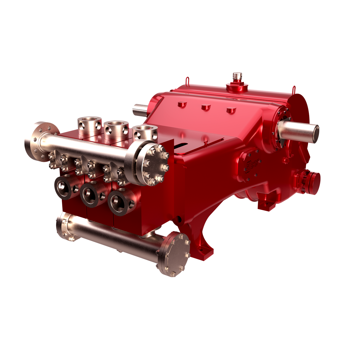
GDEP is the original creator of the drilling pump and continues to set the standard for durable, high-quality drilling pumps that can withstand the world’s toughest drilling environments. Starting with our PZ7 and rounding out with the market"s most popular pump, the PZ1600, our PZ Series of pumps are the perfect choice for today"s high-pressure drilling applications.

Triplex: This mud pump is used for drilling applications needing high pump pressure. This model works by decreasing the working fluid volume being discharged to generate pressure for producing the flow. There are three pistons in the triplex pump, with the middle piston generating more pressure on the crankshaft. High piston load can lead to excessive pressure and crankshaft failure if the components are not properly sourced.
Quintuplex:Quintuplex mud pump is perfect for pumping fluid at the time of drilling operations. It works as a continuous duty return piston. This is used in terms of its external bearings to provide crankshaft support to ensure the proper functioning of the sheaves.
Duplex: These mud pumps ensure that the mud circulation reaches the well"s bottom from the mud cleaning system. Duplex pumps have binocular floating seals as well as safety valves.
Saigao offers high-quality OEM mud pump spares, consumables, expendables and spare parts. Our mud pump parts are made with the highest standards of quality, offering competitive pricing and exceptional durability.

The present invention relates to reciprocating pumps, such as pumps of the duplex or triplex type and, more specifically, to liners for use in such pumps.
DESCRIPTION OF THE PRIOR ART In certain applications, corrosive or abrasive fluids (for example, oil well drilling fluid, commonly known as "mud"), must be pumped. Pumps used in these applications are reciprocating pumps typically of the duplex or triplex type provided with two or three cylinders, as the case may be, a piston being reciprocally disposed in each cylinder. Each cylinder communicates with a suction and discharge valve equipped chamber located at what is commonly referred to as the fluid end of the pump so that, as the piston is reciprocated by the piston rod, drilling fluid will be ultimately drawn into and discharged from the working chambers. Since the material pumped is of an abrasive character, and frequently corrosive as well, wear on the piston and cylinder wall is quite severe, and it has been common practice, in order to more easily repair a worn pump, to provide each cylinder with a replaceable steel liner that reciprocably supports the piston in the cylinder. Nevertheless, the abrasive fluid— e.g., mud— results in a relatively short lifetime of the liner and the piston, necessitating frequent replacement. It will be apparent that because of the abrasive nature of the fluids being pumped, the liner must have a hard interior surface. Additionally, because the pressures and forces that act on the liner are extreme, the liner is typically quite large and heavy.
Attempts to address the issue of making a liner that resists abrasion and corrosion and that is economical are numerous. As illustrated in U.S. Patent No. 5,617,773, incorporated herein by reference for all purposes, the industry has generally settled on a dual-metal pump liner having an abrasive and corrosive-resistant inner sleeve and a
machinable outer shell. One such liner is centrifugally cast, wherein a carbon steel outer shell is cast on the spinning mold and a high-chrome steel is then poured into the interior of a hot outer shell. Upon cooling, the result is a metallurgical bond between the inner sleeve and the outer shell, and the liner has a hard inner surface ami a machinable outer surface. However, critical spinning speeds, pour temperatures, and other parameters make such a liner process expensive and the liners difficult to make. Another method that has been used in the manufacturing of liners is a shrink fit, wherein the carbon steel shell is heated and the high chrome sleeve is cooled. The two are then press-fitted together. Upon reaching a common temperature, the sleeve has expanded and the shell has slirunk, thus creating a tight fit. Still other attempts have been made at static casting the steel shell in the sleeve; however, that method was abandoned as a failure because the brittle sleeve tended to crack.
Thus, there remains a need for a pump liner that is corrosion- and abrasion- resistant, that can withstand the pressures and forces exerted on the liner, and that is lightweight to permit easier field installation.
In copending U.S. Patent Application Serial No. 09/330,448, there is disclosed a pump liner wherein the shell is made of a composite material. As disclosed in the aforementioned U.S. patent application, the pump liners were constructed primarily by using the sleeve as a mandrel to form the shell around the sleeve // situ. While pump liners of this construction are suitable in certain applications, it has been found that in certain cases, and depending upon the construction of the pump liner, failure problems can occur. Specifically, it was noted that if the sleeve were made, as it frequently is, of a material exhibiting negligible elasticity, e.g., less than 1% elongation, the sleeve would fracture under the high pressures. In this regard, it is to be noted that most reinforcing fillers and/or materials used to form the composite shell present much greater elasticity, e.g., they exhibit elongation greater than 1%, and frequently 4 to 6%.
In mud pumps of the type under consideration, the pressures are quite high at the fluid end of the pump. Accordingly, regardless of the construction of the pump liner, e.g., whether or not the inner sleeve and the outer shell are both of metal and are essentially two separate pieces, provision must be made to ensure that the high pressures at the fluid end of the pump do not force the sleeve out of the shell.
In accordance with the present invention, there is provided a pump liner comprising a tubular sleeve having an inner corrosion- and abrasion-resistant sleeve surface and an outer sleeve surface, and a shell having an outer shell surface and an inner shell surface, the inner shell surface being in surface-to-surface engagement with the outer sleeve surface, the shell comprising a reinforcing filler supported in a polymeric matrix selected from the group consisting of thermoplastic resins, thermosetting resins, and mixtures thereof. In accordance with another embodiment of the present invention, there is provided a pump liner comprising (i) a tubular sleeve having an inner sleeve surface of a corrosion- and abrasion-resistant material and an outer sleeve surface, the outer sleeve surface being frustoconical, and (ii) a shell in surrounding relationship to the tubular sleeve, the shell having an outer shell surface and an inner shell surface, the inner shell surface being frustoconical and complementary to the outer sleeve surface. In a preferred case, the outer sleeve surface and the inner shell surface arc in interference engagement.
BRIEF DESCRIPTION OF THE DRAWINGS Fig. 1 is a simplified schematic diagram, partially in section, illustrating the pump liner of the present invention in operative position in a triplex mud pump. Fig. 2 is a sectional view taken through an axial radial plane of one embodiment of the pump liner of the present invention.
Fig. 4 is an enlarged sectional view similar to Figs. 2 and 3 showing in greater detail one form of the composite shell of the pump liner of the present invention.
Fig. 6 is a view similar to Fig. 2 showing another embodiment of the pump liner of the present invention. Fig. 7 is a view similar to Fig. 2 showing still another embodiment of the pump liner of the present invention.
DESCRIPTION OF THE PREFERRED EMBODIMENTS With reference first to Fig. 1, there is shown a triplex mud pump 10 having a cylinder 12 communicating with valve-equipped intake and exhaust chambers 14, which in turn are connected with mud supply lines, not shown. The cylinder 12 is equipped with a sleeve-like liner 16 projecting at one open end outwardly of the cylinder 12 in the direction of a piston rod 18 connected with a piston 20 for reciprocation in the liner 16 and pumping of mud from a mud circulating pit to a drill string, neither of which are shown. With reference now to Fig. 2, the pump liner 16 is seen to comprise a generally tubular, cylindrical body having an inner sleeve 22 and an outer shell 24. Inner sleeve 22 has an inner sleeve surface 26 that is corrosion- and abrasion-resistant and an outer sleeve surface 28, whereas shell 24 has an outer shell surface 30 and an inner shell surface 32. Pump liner 16 is constructed such that inner shell surface 32 is in positive, surface-to-surface contact with outer sleeve surface 28. As also seen, shell 24 has an upset portion 34 and an annular groove 36 that permit pump liner 16 to be adapted to the pump housing. The surface 26 of sleeve 22 must be of a material that is both abrasion- and corrosion-resistant. This can be accomplished by making sleeve 22 entirely of a material that possesses such properties. In this regard, typical materials that can be used include so-called white iron, which can contain alloying elements such as silicon, chromium, or nickel. For example, a cast sleeve of iron containing 23-28% chromium is frequently used as the sleeve in pump liners. Additionally, as disclosed in U.S. Patent No. 4,746,554, incorporated herein by reference for all purposes, the sleeve can be comprised of a steel tube on the internal surface on which is applied a cladding that is abrasion- and corrosion-resistant. Examples of such cladding materials that can be used to form the inner corrosion- and abrasion-resistant surface of the sleeve include Stellitc
Alloy No. 1, Stellitc Alloy No. 6, and Deloro 60, as well as various other metal oxides, borides, and carbides. Additionally, the entire sleeve can be made of a ceramic material such as a metal oxide, boride, or carbide.
Prior art pump liners use the sleeve as described above to provide the ahrasion- and corrosion-resistant inner surface upon which the seal on the piston rides, while the shell is typically made of cither a carbon steel or a low alloy steel that has sufficient wall thickness to resist the pressures and forces acting on the pump liner. Because of this construction, the pump liners of the prior art are quite heavy and difficult to manipulate in the field. In the pump liner of the present invention, the shell is a composite comprised of a reinforcing filler supported in a polymeric matrix selected from the group consisting of thermoplastic resins, thermosetting resins, and mixtures thereof. As used herein, the term "composite" means a reinforcement, referred to herein as a filler, such as fibers or particles encapsulated in and or supported by a suitable matrix or binder material such as a thermosetting and/or thermoplastic polymeric material. Generally speaking, composites of the type used herein have a discontinuous phase foπned by the filler— e.g.. fiber, particles, or the like—that is stiffer and stronger than the continuous matrix phasc- e.g., the thermosetting or thermoplastic resin. Generally speaking, the filler will be present in the composite in an amount of 7% or greater. The fillers or reinforcements that make up the composite can be fibrous, laminar, or particulate in nature. The fiber reinforcements can in turn be divided into those containing discontinuous or continuous fibers or filaments. Fiber-reinforced composites contain fillers having lengths much greater than their cross-sectional dimensions. As noted, the fibrous filler can be of the discontinuous or continuous type, a discontinuous fiber being one in which its properties vary with its length. On the other hand, a continuous fiber or filament can be considered one in which, in general, any further increase in its length does not further increase certain physical properties, e.g., the elastic modulus. Continuous reinforcing fibers or fillers are available in many product forms ranging from monofilament to multi-filament fiber bundles, and from unidirectional ribbons to single-layer fabrics and multi-layer fabric mats. Particulates are not generally useful as reinforcements in and by themselves but can be used with fiber fillers as reinforcements. Composites that are useful in the
present invention are discussed in Engineered Materials Handbook, Vol. 1: Composites, ASM International, 1987, incorporated herein by reference for all purposes.
In addition to a filler or reinforcement, the composites used in the pump liners of the present invention include, as a matrix or binder, a thermosetting resin, a thermoplastic resin, or mixtures thereof. Non-limiting examples of thermosetting resins include epoxy resins, bismaleimidc resins, polyimide resins, phenolic resins, polyurcthancs, etc., and mixtures thereof. Non-limiting examples of thermoplastic resins that can be used in the composites of the present invention include polyether etherketones, polyphenylene sulfides, polyetherimides, polyamideimides, polypropylenes, polyurethanes, etc., and mixtures thereof. It will also be appreciated that in certain cases it may be possible to use mixtures of thermoplastic and thermosetting resins, just as it is possible to use more than one type of filler or reinforcement in the composites used to make the pump liners of the present invention.
Returning to Fig. 2, shell 24, in one form, can be formed as a composite comprising windings of a suitable continuous filament coated or impregnated with a suitable thermosetting resin. For example, continuous filaments such as carbon fiber or glass fiber coated or impregnated with epoxy can be wound around sleeve 22 in successive layers until the desired radial thickness to form shell 24 is achieved. Following this, the pump liner blank can be cured to harden the epoxy matrix, following which the shell can be machined, for example, such that the upset 34 and groove 36 are formed. It will be appreciated that by using successive layers of windings as described above, a pump liner can be formed wherein the shell exhibits a very high hoop force to resist forces acting against and radially outward of the inner surface.
With reference to Fig. 5, there is shown an enlarged section of the pump liner of the present invention wherein continuous windings consisting of a suitable fibrous reinforcement have been wound around sleeve 22 to form successive layers, the layers being placed one upon the other until the desired radial thickness, indicated as D, has been achieved. It will be appreciated that the windings 50 arc essentially surrounded by a suitable thermosetting or thermoplastic matrix such that the windings 50 in combination
with the matrix essentially form a monolithic structure, the reinforcements or windings being primarily responsible for the structural strength, the matrix being responsible for bonding together the windings such that the shell retains its overall structural integrity. Alternatively, the windings of a continuous filament such as a carbon fiber or glass fiber that has been coated or impregnated with a suitable thermosetting or thermoplastic resin can be wound in various other patterns around sleeve 22 again to the desired radial thickness, whereupon the pump liner blank can then be cured and the outer surface machined.
With reference now to Fig. 3, there is shown another embodiment of the pump liner of the present invention. In the embodiment shown in Fig. 3, the pump liner shown generally as 16a has a sleeve 22 as described above; but unlike the pump liner shown in Fig. 2, the outer shell is comprised of two concentric cylindrical portions, an innermost cylindrical portion 38, and an outermost cylindrical portion 40. As can be seen, the inner surface 42 of inner cylindrical portion 38 is in surface-to-surface contact with the outer surface 28 of sleeve 22, while the outer surface 44 of inner cylindrical portion 38 is in contact with the inner cylindrical surface 46 of second or outer cylindrical portion 40. The outer surface 48 of second cylindrical portion 40, as surface 30 in the pump liner shown in the embodiment in Fig. 2, can be machined to form the upset 34 and the recess 36. Pump liner 16a, in one embodiment, could be constructed such that first or inner cylindrical portion 38 is formed of a high modulus, continuous carbon filament using an epoxy matrix, while outer or second cylindrical portion 40 could" be formed ofa medium modulus continuous glass filament using an epoxy matrix. As described above with respect to the embodiments shown in Figs.2 and 5, the respective cylindrical portions 38 and 40 could be formed in a variety of ways. For example, both cylindrical portions 38 and 40 could be formed using windings of a continuous filament to form successive layers to achieve the desired radial thickness of cylindrical portion 38 or 40, as the case may be. Alternatively, one of the cylindrical portions-e.g., cylindrical portion 38~could be of layered windings, such as shown in Fig. 5, while the outer cylindrical portion 40 could be of windings ofa continuous filament in a different form. With reference to Fig. 4, the shell is shown as being comprised of discontinuous fibers 60 of a suitable material embedded in a suitable polymeric matrix 62, the discontinuous fibers 60 having a length to diameter ratio so as to provide structural
integrity to the shell. Returning to the embodiment of Fig. 3, inner cylindrical portion 38 could be formed of windings, as shown in Fig. 5, to gain the requisite hoop force, while outer cylindrical portion 40 could be formed of discontinuous fibers in the manner shown in Fig. 4. And in still further variations, cylindrical proportions 38 and 40 could he formed in the manner shown in Fig. 4, cylindrical portion 38 using one type of discontinuous fiber and one type of thermosetting or thermoplastic resin, while outer cylindrical portion 40 is formed of a different discontinuous fiber and a different thermosetting or thermoplastic resin. It will be apparent that numerous variations of (he various embodiments described with respect to Figs. 2-5 can be employed. In addition to windings of continuous filament fillers or reinforcements, the pump liners of the present invention could be formed by compression molding or ejection or transfer molding of a suitable composite around the inner sleeve. Such a composite could use discontinuous fibers in a suitable polymeric matrix. Additionally, a flowable thermosetting resin could be transferred into a fiber-packed mold and cured around the sleeve.
In a specific method of making the pump liner of the present invention, a continuous filament— e.g., carbon, glass, or the like— is coated or impregnated with a thermosetting resin such as an epoxy resin, the coated filament being wrapped around the inner sleeve to the appropriate outer dimension— i.e., radial thickness. This preform is then placed in an oven at the appropriate temperature for a specified time to achieve a full cure. Following cooling, the pump liner preform is machined to the appropriate dimensions to fit the appropriate pump.
In another specific technique that has been employed, a thermoplastic matrix has been employed. In this technique, a suitable continuous filament such as carbon, glass, or the like is coated or impregnated with a thermoplastic resin that has been heated so as to stay in a molten or flowable state while the continuous, coated filament is wrapped around the inner sleeve. Following cooling, the composite sets and the shell can be machined to its final dimension. It will also be apparent that the pump liner could be formed by first wrapping the sleeve with the appropriate rcinfoicemcnt-e.g., a continuous fiber wound around to the desired thickness— to foπn a prcfonn, which could then be placed into a mold and a thermoplastic or thermosetting resin added to the mold, which would then be cured in the appropriate fashion, depending upon whether the
plastic matrix was thermosetting or thermoplastic in nature. Once the composite is cured, the outer surface of the shell could then be machined to the desired configuration and dimension. In this last method of forming the pump liner—more specifically, the shell-it will be appreciated that the filler is not coated or impregnated with the thermoplastic or thermosetting resin in the more conventional fashion wherein, for example, the continuous filament of the reinforcement is calendered through a bath of the resin and then wound around the sleeve. Nonetheless, the thermosetting or thermoplastic resin would still support the reinforcement, e.g., the continuous filament.
With reference now to Fig. 6, a pump liner according to the present invention, shown generally as 70, is seen to comprise a composite shell 72 in surrounding relationship to a sleeve 74, sleeve 74 being of metallic construction. Pump liner 70 has a first end 76 and a second end 78. Pump liner 70 is provided with an upset portion 79 adjacent the first end 76, which, as described above with respect to the other pump liners, permits pump liner 70 to be connected to a pump housing and, more specifically, to the fluid end of the pump. Rather than having a cylindrical outer surface as discussed above with respect to the other pump liner, sleeve 74 has a frustoconical surface 80, the largest diameter of which is located adjacent the first end 76 of pump liner 70. In like fashion, rather than having a cylindrical inner surface, shell 72 is provided with a frustoconical inner surface 82, the smallest diameter of which is located adjacent first end 76. As can be seen, frustoconical surfaces 80 and 82 are complementary to one another. More particularly, in a preferred embodiment, shell 72 is formed separately from sleeve 74 by any of the techniques discussed above or any other suitable technique, after which sleeve 74 is press-fitted into shell 72, sleeve 74 and shell 72 being dimensioned such that there is interference engagement between outer surface 80 of sleeve 74 and inner surface 82 of shell 72. The degree of interference engagement between the sleeve 74 and the shell 72 is dependent upon the respective materials from which the sleeve and shell are made; however, in general, the radial interference between sleeve 74 and shell 72 will be greater than about 0.001 inches, although greater radial interferences, e.g., 0.015 to 0.030 inches, are typically employed. By providing interference engagement between outer surface 80 and inner surface 82, sleeve 74 is subjected to what can be characterized as hoop stress exerted by shell 72, the hoop stress being sufficient to maintain a radially inward compressive force on sleeve 74, preventing its fracture when subjected to the high
pressures normally encountered. It is also to be observed that any force exerted by hydraulic pressure from the fluid end of the pump-i.e., adjacent end 76 of pump liner 70— and that acts against sleeve 74 in the direction of arrow A will only serve to force frustoconical surfaces 80 and 82 into tighter engagement. Moreover, because of the engaged frustoconical surfaces 80, 82, it can be seen that hydraulic pressure from the fluid end of the pump cannot force sleeve 74 out of shell 72.
With reference now to Fig. 7, there is shown a variation of the pump liner 70 shown in Fig. 6. Pump liner 90 is comprised of a shell 92 having a radially outermost portion 94 and a radially innermost portion 96, portions 94 and 96 being composite in nature as that term is used above. Pump liner 90 further includes a sleeve 104, shell 92 being in surrounding relationship to sleeve 104. Pump liner 90 further has a first end 98 and a second end 100, first end 98 being adapted be connected to the fluid end of the pump, an upset portion 102 being formed on outer shell portion 94 for this purpose. Whereas sleeve 74 in pump liner 70 is metallic in construction, sleeve 104 is of ceramic construction. As can be seen, radially innermost portion 96 of shell 92 has an inner surface 106 that is frustoconical, while sleeve 104 has an outer surface 108 that is likewise frustoconical and is complementary to frustoconical surface 106.
As described above with respect to pump liner 70, pump liner 90 is typically constructed by forming shell 92 as a separate piece and press-fitting sleeve 104 into shell 92, the dimensioning of shell 92 and sleeve 104 being such that surfaces 108 and 106 arc in interference engagement. As in the case of pump liner 70, pump liner 90 provides a structure wherein the sleeve 104 can be made ofa material possessing low elasticity but which nonetheless is prevented from fracturing even under high pressures because of the radially inwardly directed compressive force exerted by shell 92. Additionally, it can be seen that sleeve 104, when subjected to pressure in the direction of arrow B, is forced into even tighter engagement with shell 92 and is prevented from being expelled from shell 92 because of the engaged frustoconical surfaces 106 and 108.
While pump liners 70 and 90 have been described above with respect to an interference fit between the sleeves and the shells, it is to be understood that, depending upon the type of pressures to which the pump liner is subjected, the material of construction of the sleeve, and the material of construction of the shell, a true interference fit may not be necessary, albeit that the sleeves and the shells would have frustoconical
surfaces for the purpose of preventing the sleeves from being dislodged from the shells. In such circumstances, the shell would exert no radially inward compressive force on the sleeve, albeit that the outer surface of the sleeve and the inner surface of the shell may be in surface engagement. Accordingly, for purposes herein, the term "interference" or "interference fit" is intended to mean a condition wherein because of relative dimensioning or otherwise, e.g., the application of some external force around the outer surface of the shells, there is a radially inwardly directed compressive force exerted by the shell on the sleeve. As noted above, this is most easily accomplished by dimensioning the sleeve and the shell such that the sleeve can be press-fitted into the shell under the exertion ofa force that results in at least some degree of radially outward elastic deformation of the shell, resulting in a continuous radially inwardly directed compressive force on the sleeve. By achieving an interference fit between the sleeve and the shell, the sleeve can be constructed of materials that exhibit excellent corrosion and abrasion resistance but possess little or no elasticity. Non-limiting examples of such materials include cl rome cast iron, ceramics, and the like.
It will be understood that the discussion herein regarding the composition of the composites is applicable to the embodiments of Figs. 6 and 7, as well as the embodiments shown in Figs. 2-5. Additionally, it will be appreciated that the sleeve of the embodiments shown in Figs. 6 and 7 can be comprised of materials described above with respect to any of the embodiments shown in Figs. 2-5. Lastly, the principles of construction of the pump liner shown in Figs. 6 and 7 can be used wherein the sleeve and shell are both of metallic construction.
The term "support" as used herein, and with reference to the relationship between the filler/reinforcement and the polymeric matrix, is intended to encompass impregnation or coating of the filler prior to forming the shell, winding a matrix-free, continuous filament around the sleeve or a mandrel to the desired radial thickness, and then adding the polymeric matrix in a mold; filling a mold with discontinuous fibers, and then adding a suitable polymeric matrix, etc. In general, the word "support" is intended to encompass any structural relationship between the filler/ reinforcement and the polymeric matrix wherein the filler/reinforcement is essentially immobilized in the shell once the shell has been cured, whether the shell is formed in situ on the sleeve or separately from the sleeve. For example, in the embodiment shown in Fig. 5, where a continuous filament is wound
It will be appreciated that with respect to the embodiments shown in Figs. 2-5, the outer sleeve surface can be a smooth, cylindrical surface or, more preferably, can have formations that serve to grip the inner surface of the shell to prevent relative movement between the sleeve and the shell. Thus, for example, the outer surface of the sleeve could be provided with serrations, threads, or other such projections that would effectively mechanically grip the shell, preventing any relative rotation or longitudinal movement between the shell and the sleeve. As noted above, one of the drawbacks of conventional pump liners that are used in mud pumps is their weight, and the concomitant difficulty is replacing the pump liners in the field. A conventional six-inch pump liner weighs approximately 130 to 140 lbs., whereas a pump liner of the same dimension made in accordance with the present invention would weigh approximately 40 to 50 lbs. The advantages of such a dramatic reduction in weight arc obvious. Additionally, in conventional pump liners, while the inner sleeve is corrosion-resistant, the shell that is normally made of carbon steel is not corrosion-resistant. However, with the pump liners of the present invention, both the sleeve and the shell would be corrosion-resistant.
Lake Petro provides high quality Mud Pump Parts including Mud Pump Liners, Mud Pump Fluid End Module, piston, Valve and Seat etc. With more than 10 years of experience in the oil and gas industry, we are dedicated to help and support our loyal clients with the most cost-effective and quality Liners and Pistons. We also provide mud pump price and mud pump for sale.
We offer Liners with Ceramic (Zirconia and Aluminium oxide) and Steel (Metal and Bi-metal) materials for all common brands of the mud pump and triplex mud pump.
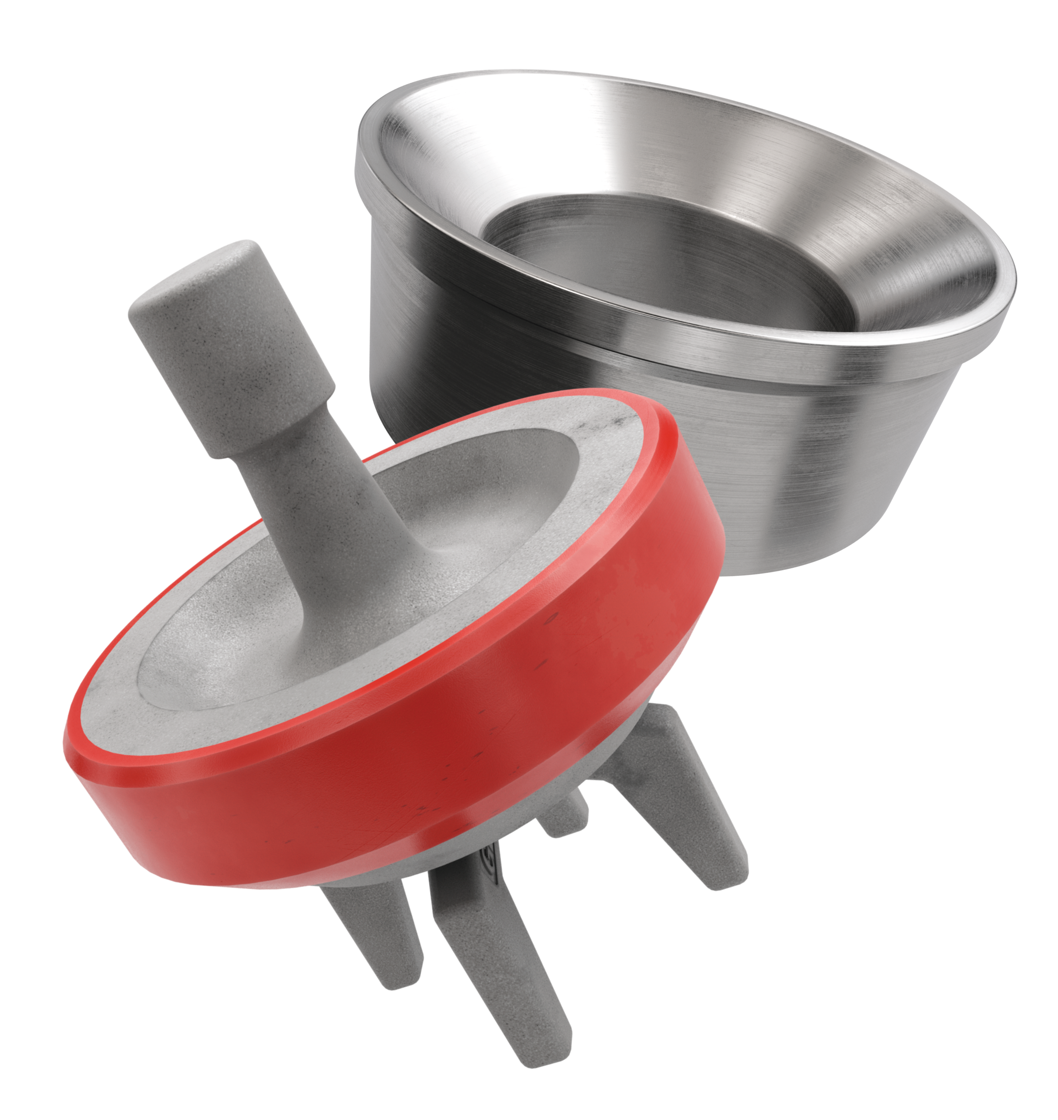
Bi-metal liners (double metal liners) are made of forged steel shell and wear-resistant sleeve of high chromium iron. In the production process, the size accuracy should be strictly controlled, which can ensure that they can be easily and stably installed. The inner sleeve with high finish and hardness is wear-resistant, corrosion-resistant and has a long service life. The bi-metal liners are suitable for a lot of bad working conditions. Its service life is more than 800 hours.
Ceramic Liners are made of a ceramic inner sleeve and a forged steel outer shell. The service life of ceramic liners is about 4000 to 10000 hours, the minimum time is at least 2000 hours, which is a lot more than bi-metal liners. Because of the phase transformation toughen technology, the ceramic liners have the features of wear-resistance, erosion-resistance, high-pressure-resistance, high hardness and strength. Zirconia type and Alumina type are common type of ceramic sleeve. Compared with Alumina type, Zirconia type liners have better toughness properties and a much longer service life. Piston wear and water consumption for lubrication can be reduced as well.
Seal Rings for Liner packing are also important. Liner Seal Rings is designed and made with hard corner which is an integral part of seal rings and soft nitrile element rubber center. We could provide reliable liner Seal Rings for our customers could order them at the same time.
All Lake Petro liner products are interchangeable with O.E.M. products. Meanwhile, we provide customized Liners according to drawings. Our liners, also with our other mud pump spares, are supplied for use in Honghua, F-Series, Bomco, Emsco and National lines of triplex drilling pumps. Let Lake Petro be your one-stop shop for your whole fleet of pumps. Please refer to “Suitable Pump Models” Lable for more details.

A steamboat is a boat that is propelled primarily by steam power, typically driving propellers or paddlewheels. Steamboats sometimes use the prefix designation SS, S.S. or S/S (for "Screw Steamer") or PS (for "Paddle Steamer"); however, these designations are most often used for steamships.
The term steamboat is used to refer to smaller, insular, steam-powered boats working on lakes and rivers, particularly riverboats. As using steam became more reliable, steam power became applied to larger, ocean-going vessels.
Early steamboat designs used Newcomen steam engines. These engines were large, heavy, and produced little power, which resulted in an unfavorable power-to-weight ratio. The Newcomen engine also produced a reciprocating or rocking motion because it was designed for pumping. The piston stroke was caused by a water jet in the steam-filled cylinder, which condensed the steam, creating a vacuum, which in turn caused atmospheric pressure to drive the piston downward. The piston relied on the weight of the rod connecting to the underground pump to return the piston to the top of the cylinder. The heavy weight of the Newcomen engine required a structurally strong boat, and the reciprocating motion of the engine beam required a complicated mechanism to produce propulsion.
James Watt"s design improvements increased the efficiency of the steam engine, improving the power-to-weight ratio, and created an engine capable of rotary motion by using a double-acting cylinder which injected steam at each end of the piston stroke to move the piston back and forth. The rotary steam engine simplified the mechanism required to turn a paddle wheel to propel a boat. Despite the improved efficiency and rotary motion, the power-to-weight ratio of Boulton and Watt steam engine was still low.
The high-pressure steam engine was the development that made the steamboat practical. It had a high power-to-weight ratio and was fuel efficient. High pressure engines were made possible by improvements in the design of boilers and engine components so that they could withstand internal pressure, although boiler explosions were common due to lack of instrumentation like pressure gauges.Boulton and Watt patent in 1800. Shortly thereafter high-pressure engines by Richard Trevithick and Oliver Evans were introduced.
The compound steam engine became widespread in the late 19th century. Compounding uses exhaust steam from a high pressure cylinder to a lower pressure cylinder and greatly improves efficiency. With compound engines it was possible for trans ocean steamers to carry less coal than freight.
The most efficient steam engine used for marine propulsion is the steam turbine. It was developed near the end of the 19th century and was used throughout the 20th century.
An apocryphal story from 1851 attributes the earliest steamboat to Denis Papin for a boat he built in 1705. Papin was an early innovator in steam power and the inventor of the steam digester, the first pressure cooker, which played an important role in James Watt"s steam experiments. However, Papin"s boat was not steam-powered but powered by hand-cranked paddles.
A steamboat was described and patented by English physician John Allen in 1729.Jonathan Hulls was granted a patent in England for a Newcomen engine-powered steamboat (using a pulley instead of a beam, and a pawl and ratchet to obtain rotary motion), but it was the improvement in steam engines by James Watt that made the concept feasible. William Henry of Lancaster, Pennsylvania, having learned of Watt"s engine on a visit to England, made his own engine, and put it in a boat. The boat sank, and while Henry made an improved model, he did not appear to have much success, though he may have inspired others.
The first steam-powered ship Newcomen steam engine; it was built in France in 1783 by Marquis Claude de Jouffroy and his colleagues as an improvement of an earlier attempt, the 1776 Palmipède. At its first demonstration on 15 July 1783, Pyroscaphe travelled upstream on the river Saône for some fifteen minutes before the engine failed. Presumably this was easily repaired as the boat is said to have made several such journeys.
Similar boats were made in 1785 by John Fitch in Philadelphia and William Symington in Dumfries, Scotland. Fitch successfully trialled his boat in 1787, and in 1788, he began operating a regular commercial service along the Delaware River between Philadelphia and Burlington, New Jersey, carrying as many as 30 passengers. This boat could typically make 7 to 8 miles per hour (11 to 13 km/h) and travelled more than 2,000 miles (3,200 km) during its short length of service. The Fitch steamboat was not a commercial success, as this travel route was adequately covered by relatively good wagon roads. The following year, a second boat made 30-mile (48 km) excursions, and in 1790, a third boat ran a series of trials on the Delaware River before patent disputes dissuaded Fitch from continuing.
Meanwhile, Patrick Miller of Dalswinton, near Dumfries, Scotland, had developed double-hulled boats propelled by manually cranked paddle wheels placed between the hulls, even attempting to interest various European governments in a giant warship version, 246 feet (75 m) long. Miller sent King Gustav III of Sweden an actual small-scale version, 100 feet (30 m) long, called Experiment.William Symington to build his patent steam engine that drove a stern-mounted paddle wheel in a boat in 1785. The boat was successfully tried out on Dalswinton Loch in 1788 and was followed by a larger steamboat the next year. Miller then abandoned the project.
The failed project of Patrick Miller caught the attention of Lord Dundas, Governor of the Forth and Clyde Canal Company, and at a meeting with the canal company"s directors on 5 June 1800, they approved his proposals for the use of "a model of a boat by Captain Schank to be worked by a steam engine by Mr Symington" on the canal.
The boat was built by Alexander Hart at Grangemouth to Symington"s design with a vertical cylinder engine and crosshead transmitting power to a crank driving the paddlewheels. Trials on the River Carron in June 1801 were successful and included towing sloops from the river Forth up the Carron and thence along the Forth and Clyde Canal.
In 1801, Symington patented a horizontal steam engine directly linked to a crank. He got support from Lord Dundas to build a second steamboat, which became famous as the Carron Company.
The first sailing was on the canal in Glasgow on 4 January 1803, with Lord Dundas and a few of his relatives and friends on board. The crowd were pleased with what they saw, but Symington wanted to make improvements and another more ambitious trial was made on 28 March. On this occasion, the Charlotte Dundas towed two 70 ton barges 30 km (almost 20 miles) along the Forth and Clyde Canal to Glasgow, and despite "a strong breeze right ahead" that stopped all other canal boats it took only nine and a quarter hours, giving an average speed of about 3 km/h (2 mph). The Charlotte Dundas was the first practical steamboat, in that it demonstrated the practicality of steam power for ships, and was the first to be followed by continuous development of steamboats.
The American Robert Fulton was present at the trials of the Charlotte Dundas and was intrigued by the potential of the steamboat. While working in France, he corresponded with and was helped by the Scottish engineer Henry Bell, who may have given him the first model of his working steamboat.River Seine in 1803.
Fulton later obtained a Boulton and Watt steam engine, shipped to America, where his first proper steamship was built in 1807,Clermont), which carried passengers between New York City and Albany, New York. Clermont was able to make the 150-mile (240 km) trip in 32 hours. The steamboat was powered by a Boulton and Watt engine and was capable of long-distance travel. It was the first commercially successful steamboat, transporting passengers along the Hudson River.
In October 1811 a ship designed by John Stevens, Little Juliana, would operate as the first steam-powered ferry between Hoboken and New York City. Stevens" ship was engineered as a twin-screw-driven steamboat in juxtaposition to Clermont"s Boulton and Watt engine.Phoenix, the first steamship to successfully navigate the open ocean in its route from Hoboken to Philadelphia.
The Margery, launched in Dumbarton in 1814, in January 1815 became the first steamboat on the River Thames, much to the amazement of Londoners. She operated a London-to-Gravesend river service until 1816, when she was sold to the French and became the first steamboat to cross the English Channel. When she reached Paris, the new owners renamed her Elise and inaugurated a Seine steamboat service.
The first sea-going steamboat was Richard Wright"s first steamboat "Experiment", an ex-French lugger; she steamed from Leeds to Yarmouth, arriving Yarmouth 19 July 1813.
Steamships required carrying fuel (coal) at the expense of the regular payload. For this reason for some time sailships remained more economically viable for long voyages. However, as the steam engine technology improved, more power could be generated by the same quantity of fuel and longer distances could be traveled. A steamship built in 1855 required about 40% of its available cargo space to store enough coal to cross the Atlantic, but by the 1860s, transatlantic steamship services became cost-effective and steamships began to dominate these routes. By the 1870s, particularly in conjunction with the opening of the Suez Canal in 1869, South Asia became economically accessible for steamships from Europe. By the 1890s, the steamship technology so improved that steamships became economically viable even on long-distance voyages such as linking Great Britain with its Pacific Asian colonies, such as Singapore and Hong Kong. This resulted in the downfall of sailing.
The era of the steamboat in the United States began in Philadelphia in 1787 when John Fitch (1743–1798) made the first successful trial of a 45-foot (14-meter) steamboat on the Delaware River on 22 August 1787, in the presence of members of the United States Constitutional Convention. Fitch later (1790) built a larger vessel that carried passengers and freight between Philadelphia and Burlington, New Jersey on the Delaware. His steamboat was not a financial success and was shut down after a few months service, however this marks the first use of marine steam propulsion in scheduled regular passenger transport service.
Oliver Evans (1755–1819) was a Philadelphian inventor born in Newport, Delaware, to a family of Welsh settlers. He designed an improved high-pressure steam engine in 1801 but did not build itOruktor Amphibolos. It was built but was only marginally successful.power-to-weight ratio, making it practical to apply it in locomotives and steamboats.
Robert Fulton constructed a steamboat to ply a route between New York City and Albany, New York on the Hudson River. He successfully obtained a monopoly on Hudson River traffic after terminating a prior 1797 agreement with John Stevens, who owned extensive land on the Hudson River in New Jersey. The former agreement had partitioned northern Hudson River traffic to Livingston and southern to Stevens, agreeing to use ships designed by Stevens for both operations.Clermont after Livingston"s estate, could make a profit. The Clermont was nicknamed "Fulton"s Folly" by doubters. On Monday, 17 August 1807, the memorable first voyage of the Clermont up the Hudson River was begun. She traveled the 150 miles (240 km) trip to Albany in a little over 32 hours and made the return trip in about eight hours.
The use of steamboats on major US rivers soon followed Fulton"s 1807 success. In 1811 the first in a continuous (still in commercial passenger operation as of 2007Pittsburgh to steam down the Ohio River to the Mississippi and on to New Orleans.Sackets Harbor, New York, funded the construction of the first US steamboat, Ontario, to run on Lake Ontario and the Great Lakes, beginning the growth of lake commercial and passenger traffic.river pilot and author Mark Twain described much of the operation of such vessels.
By 1849 the shipping industry was in transition from sail-powered boats to steam-powered boats and from wood construction to an ever-increasing metal construction. There were basically three different types of ships being used: standard sailing ships of several different types,clippers, and paddle steamers with paddles mounted on the side or rear. River steamboats typically used rear-mounted paddles and had flat bottoms and shallow hulls designed to carry large loads on generally smooth and occasionally shallow rivers. Ocean-going paddle steamers typically used side-wheeled paddles and used narrower, deeper hulls designed to travel in the often stormy weather encountered at sea. The ship hull design was often based on the clipper ship design with extra bracing to support the loads and strains imposed by the paddle wheels when they encountered rough water.
The first paddle-steamer to make a long ocean voyage was the 320-ton 98-foot-long (30 m) SS Savannah, built in 1819 expressly for packet ship mail and passenger service to and from Liverpool, England. On 22 May 1819, the watch on the Savannah sighted Ireland after 23 days at sea. The Allaire Iron Works of New York supplied Savannah"s"s engine cylinder,Speedwell Ironworks of New Jersey. The 90-horsepower (67 kW) low-pressure engine was of the inclined direct-acting type, with a single 40-inch-diameter (100 cm) cylinder and a 5-foot (1.5 m) stroke. Savannah"s engine and machinery were unusually large for their time. The ship"s wrought-iron paddlewheels were 16 feet in diameter with eight buckets per wheel. For fuel, the vessel carried 75 short tons (68 t) of coal and 25 cords (91 m3) of wood.
The SS Savannah was too small to carry much fuel, and the engine was intended only for use in calm weather and to get in and out of harbors. Under favorable winds the sails alone were able to provide a speed of at least four knots. The Savannah was judged not a commercial success, and its engine was removed and it was converted back to a regular sailing ship. By 1848 steamboats built by both United States and British shipbuilders were already in use for mail and passenger service across the Atlantic Ocean—a 3,000 miles (4,800 km) journey.
Since paddle steamers typically required from 5 to 16 short tons (4.5 to 14.5 t) of coal per day to keep their engines running, they were more expensive to run. Initially, nearly all seagoing steamboats were equipped with mast and sails to supplement the steam engine power and provide power for occasions when the steam engine needed repair or maintenance. These steamships typically concentrated on high value cargo, mail and passengers and only had moderate cargo capabilities because of their required loads of coal. The typical paddle wheel steamship was powered by a coal burning engine that required firemen to shovel the coal to the burners.
By 1849 the screw propeller had been invented and was slowly being introduced as iron increasingly was used in ship construction and the stress introduced by propellers could be compensated for. As the 1800s progressed the timber and lumber needed to make wooden ships got ever more expensive, and the iron plate needed for iron ship construction got much cheaper as the massive iron works at Merthyr Tydfil, Wales, for example, got ever more efficient. The propeller put a lot of stress on the rear of the ships and would not see widespread use till the conversion from wood boats to iron boats was complete—well underway by 1860. By the 1840s the ocean-going steam ship industry was well established as the Cunard Line and others demonstrated.
In the mid-1840s the acquisition of Oregon and California opened up the West Coast to American steamboat traffic. Starting in 1848 Congress subsidized the Pacific Mail Steamship Company with $199,999 to set up regular packet ship, mail, passenger, and cargo routes in the Pacific Ocean. This regular scheduled route went from Panama City, Nicaragua and Mexico to and from San Francisco and Oregon. Panama City was the Pacific terminus of the Isthmus of Panama trail across Panama. The Atlantic Ocean mail contract from East Coast cities and New Orleans to and from the Chagres River in Panama was won by the United States Mail Steamship Company whose first paddle wheel steamship, the SS Falcon (1848) was dispatched on 1 December 1848 to the Caribbean (Atlantic) terminus of the Isthmus of Panama trail—the Chagres River.
The SS California (1848), the first Pacific Mail Steamship Company paddle wheel steamship, left New York City on 6 October 1848 with only a partial load of her about 60 saloon (about $300 fare) and 150 steerage (about $150 fare) passenger capacity. Only a few were going all the way to California.California Gold Rush had reached the East Coast. Once the California Gold Rush was confirmed by President James Polk in his State of the Union address on 5 December 1848 people started rushing to Panama City to catch the SS California. The SS California picked up more passengers in Valparaiso, Chile and Panama City, Panama and showed up in San Francisco, loaded with about 400 passengers—twice the passengers it had been designed for—on 28 February 1849. She had left behind about another 400–600 potential passengers still looking for passage from Panama City. The SS Californiahad made the trip from Panama and Mexico after steaming around Cape Horn from New York—see SS California (1848).
The trips by paddle wheel steamship to Panama and Nicaragua from New York, Philadelphia, Boston, via New Orleans and Havana were about 2,600 miles (4,200 km) long and took about two weeks. Trips across the Isthmus of Panama or Nicaragua typically took about one week by native canoe and mule back. The 4,000 miles (6,400 km) trip to or from San Francisco to Panama City could be done by paddle wheel steamer in about three weeks. In addition to this travel time via the Panama route typically had a two- to four-week waiting period to find a ship going from Panama City, Panama to San Francisco before 1850. It was 1850 before enough paddle wheel steamers were available in the Atlantic and Pacific routes to establish regularly scheduled journeys.
Other steamships soon followed, and by late 1849, paddle wheel steamships like the SS McKim (1848)Sacramento–San Joaquin River Delta to Stockton, California, Marysville, California, Sacramento, etc. to get about 125 miles (201 km) closer to the gold fields. Steam-powered tugboats and towboats started working in the San Francisco Bay soon after this to expedite shipping in and out of the bay.
As the passenger, mail and high value freight business to and from California boomed more and more paddle steamers were brought into service—eleven by the Pacific Mail Steamship Company alone. The trip to and from California via Panama and paddle wheeled steamers could be done, if there were no waits for shipping, in about 40 days—over 100 days less than by wagon or 160 days less than a trip around Cape Horn. About 20–30% of the California Argonauts are thought to have returned to their homes, mostly on the East Coast of the United States via Panama—the fastest way home. Many returned to California after settling their business in the East with their wives, family and/or sweethearts. Most used the Panama or Nicaragua route till 1855 when the completion of the Panama Railroad made the Panama Route much easier, faster and more reliable. Between 1849 and 1869 when the first transcontinental railroad was completed across the United States about 800,000 travelers had used the Panama route.Panama Railroad across Panama. After 1855 when the Panama Railroad was completed the Panama Route was by far the quickest and easiest way to get to or from California from the East Coast of the U.S. or Europe. Most California bound merchandise still used the slower but cheaper Cape Horn sailing ship route. The sinking of the paddle steamer SS Central America (the Ship of Gold) in a hurricane on 12 September 1857 and the loss of about $2 million in California gold indirectly led to the Panic of 1857.
Steamboat traffic including passenger and freight business grew exponentially in the decades before the Civil War. So too did the economic and human losses inflicted by snags, shoals, boiler explosions, and human error.
During the US Civil War the Battle of Hampton Roads, often referred to as either the Battle of the Merrimack or the Battle of Ironclads, was fought over two days with steam-powered ironclad warships, 8–9 March 1862. The battle occurred in Hampton Roads, a roadstead in Virginia where the Elizabeth and Nansemond Rivers meet the James River just before it enters Chesapeake Bay adjacent to the city of Norfolk. The battle was a part of the effort of the Confederate States of America to break the Union Naval blockade, which had cut off Virginia from all international trade.
Although Union forces gained control of Mississippi River tributaries, travel there was still subject to interdiction by the Confederates. The Ambush of the steamboat J. R. Williams, which was carrying supplies from Fort Smith to Fort Gibson along the Arkansas River on 16 July 1863 demonstrated this. The steamboat was destroyed, the cargo was lost, and the tiny Union escort was run off. The loss did not affect the Union war effort, however.
For most of the 19th century and part of the early 20th century, trade on the Mississippi River was dominated by paddle-wheel steamboats. Their use generated rapid development of economies of port cities; the exploitation of agricultural and commodity products, which could be more easily transported to markets; and prosperity along the major rivers. Their success led to penetration deep into the continent, where Canada–US border on the Red River. They would also be involved in major political events, as when Louis Riel seized Fort Garry, or Gabriel Dumont was engaged by Batoche. Steamboats were held in such high esteem that they could become state symbols; the Steamboat Iowa (1838) is incorporated in the Seal of Iowa because it represented speed, power, and progress.
At the same time, the expanding steamboat traffic had severe adverse environmental effects, in the Middle Mississippi Valley especially, between St. Louis and the river"s confluence with the Ohio. The steamboats consumed much wood for fuel, and the river floodplain and banks became deforested. This led to instability in the banks, addition of silt to the water, making the river both shallower and hence wider and causing unpredictable, lateral movement of the river channel across the wide, ten-mile floodplain, endangering navigation. Boats designated as snagpullers to keep the channels free had crews that sometimes cut remaining large trees 100–200 feet (30–61 m) or more back from the banks, exacerbating the problems. In the 19th century, the flooding of the Mississippi became a more severe problem than when the floodplain was filled with trees and brush.
Most steamboats were destroyed by boiler explosions or fires—and many sank in the river, with some of those buried in silt as the river changed course. From 1811 to 1899, 156 steamboats were lost to snags or rocks between St. Louis and the Ohio River. Another 411 were damaged by fire, explosions or ice during that period.museum ship at Winona, Minnesota, until its destruction in a fire in 1981. The replacement, built in situ, was not a steamboat. The replica was scrapped in 2008.
From 1844 through 1857, luxurious palace steamers carried passengers and cargo around the North American Great Lakes.Great Lakes passenger steamers reached their zenith during the century from 1850 to 1950. The SS Badger is the last of the once-numerous passenger-carrying steam-powered car ferries operating on the Great Lakes. A unique style of bulk carrier known as the lake freighter was developed on the Great Lakes. The St. Marys Challenger, launched in 1906, is the oldest operating steamship in the United States. She runs a Skinner Marine Unaflow 4-cylinder reciprocating steam engine as her power plant.
Women started to become steamboat captains in the late 19th century. The first woman to earn her steamboat master"s license was Mary Millicent Miller, in 1884.Callie Leach French earned her first class license.master"s license, becoming the only woman to hold both and operating on the Mississippi River.Blanche Douglass Leathers, who earned her license in 1894.Mary Becker Greene earned her license in 1897 and along with her husband started the Greene Line.
In the late 1830s, the steamboats in rivers on the west side of the Mississippi River were a long, wide, shallow draft vessel, lightly built with an engine on the deck. These newer steamboats could sail in just 20 inches of water. Contemporaries claimed that they could "run with a lot of heavy dew".
Walking the boat was a way of lifting the bow of a steamboat like on crutches, getting up and down a sandbank with poles, blocks, and strong rigging, and using paddlewheels to lift and move the ship through successive steps, on the helm. Moving of a boat from a sandbar was by its own action known as "walking the boat" and "grass-hoppering". Two long, strong poles were pushed forward from the bow on either side of the boat into the sandbar at a high degree of angle. Near the end of each pole, a block was secured with a strong rope or clamp that passed through pulleys that lowered through a pair of similar blocks attached to the deck near the bow. The end of each line went to a winch which, when turned, was taut and, with its weight on the stringers, slightly raised the bow of the boat. Activation of the forward paddlewheels and placement of the poles caused the bow of the boat to raise and move the boat forward perhaps a few feet. It was laborious and dangerous work for the crew, even with a Steam donkey driven capstan winch.
Double-tripping means making two voyages by leaving a cargo of a steamboat ashore to lighten boats load during times of extremely low water or when ice impedes progress. The boat had to return (and therefore make a second trip) to retrieve the cargo.
1862: The Allen steam engine (later called Porter-Allen) is exhibited at the London Exhibition. It is precision engineered and balanced allowing it to operate at from three to five times the speed of other stationary engines. The short stroke and high speed minimize condensation in the cylinder, significantly improving efficiency. The high speed allows direct coupling or the use of reduced sized pulleys and belting.
1867(1867): Stephen Wilcox and his partner George Herman Babcock patent the "Babcock & Wilcox Non-Explosive Boiler", which uses water inside clusters of tubing to generate steam, typically with higher pressures and more efficiently than the typical "firetube" boilers of that time. Babcock & Wilcox-type boiler designs become popular in new installations.
1884(1884): Charles Algernon Parsons develops the steam turbine. Used early on in electrical generation and to power ships, turbines were bladed wheels that created rotary motion when high pressure steam was passed through them. The efficiency of large steam turbines was considerably better than the best compound engines, while also being much simpler, more reliable, smaller and lighter all at the same time. Steam turbines would eventually replace piston engines for most power generation.
Five major commercial steamboats currently operate on the inland waterways of the United States. The only remaining overnight cruising steamboat is the 432-passenger Chautauqua Lake, New York, Lake George, New York, operating on Lake George; the Louisville, Kentucky, operating on the Ohio River; and the Riverboat article.
In Canada, the city of Terrace, British Columbia, celebrates "Riverboat Days" each summer. Built on the banks of the Skeena River, the city depended on the steamboat for transportation and trade into the 20th century. The first steamer to enter the Skeena was Union in 1864. In 1866 Mumford attempted to ascend the river, but it was only able to reach the Kitsumkalum River. It was not until 1891 Hudson"s Bay Company sternwheeler Caledonia successfully negotiated Kitselas Canyon and reached Hazelton. A number of other steamers were built around the turn of the 20th century, in part due to the growing fish industry and the gold rush.Steamboats of the Skeena River.
The simplicity of these vessels and their shallow draft made them indispensable to pioneer communities that were otherwise virtually cut off from the outside world. Because of their shallow, flat-bottomed construction (the Canadian examples of the western river sternwheeler generally needed less than three feet of water to float in), they could nose up almost anywhere along a riverbank to pick up or drop off passengers and freight. Sternwheelers would also prove vital to the construction of the railroads that eventually replaced them. They were used to haul supplies, track and other materials to construction camps.
The simple, versatile, locomotive-style boilers fitted to most sternwheelers after about the 1860s could burn coal, when available in more populated areas like the lakes of the Kootenays and the Okanagan region in southern BC, or wood in the more remote areas, such as the Steamboats of the Yukon River or northern BC.
In British Columbia, the Kootenay Lake in south-eastern BC until 1957. It has been carefully restored and is on display in the village of Kaslo, where it acts as a tourist attraction right next to information centre in downtown Kaslo. The Moyie is the world"s oldest intact stern wheeler. While the SS Sicamous and SS Naramata (steam tug & icebreaker) built by the CPR at Okanagan Landing on Okanagan Lake in 1914Okanagan Lake.
The SS Samson V is the only Canadian steam-powered sternwheeler that has been preserved afloat. It was built in 1937 by the Canadian federal Department of Public Works as a snagboat for clearing logs and debris out of the lower reaches of the Fraser River and for maintaining docks and aids to navigation. The fifth in a line of Fraser River snagpullers, the Samson V has engines, paddlewheel and other components that were passed down from the Samson II of 1914. It is now moored on the Fraser River as a floating museum in its home port of New Westminster, near Vancouver, BC.
The oldest operating steam driven vessel in North America is the RMS Segwun. It was built in Scotland in 1887 to cruise the Muskoka Lakes, District of Muskoka, Ontario, Canada. Originally named the S.S. Nipissing, it was converted from a side-paddle-wheel steamer with a walking-beam engine into a two-counter-rotating-propeller steamer.
Engineer Robert Fourness and his cousin, physician James Ashworth are said to have had a steamboat running between Hull and Beverley, after having been granted British Patent No. 1640 of March 1788 for a "new invented machine for working, towing, expediting and facilitating the voyage of ships, sloops and barges and other vessels upon the water". James Oldham, MICE, described how well he knew those who had built the F&A steamboat in a lecture entitled "On the rise, progress and present position of steam navigation in Hull" that he gave at the 23rd Meeting of the British Association for the Advancement for Science in Hull, England on 7 September 1853.
The first commercially successful steamboat in Europe, Henry Bell"s Firth of Clyde, and within four years a steamer service was in operation on the inland Loch Lomond, a


 8613371530291