
steam engine made from mud pump liners in stock
GDEP is the original creator of the drilling pump and continues to set the standard for durable, high-quality drilling pumps that can withstand the world’s toughest drilling environments. Starting with our PZ7 and rounding out with the market"s most popular pump, the PZ1600, our PZ Series of pumps are the perfect choice for today"s high-pressure drilling applications.
Manufactured 1998, 1602 hours, 4" plungers with hydraulic charge pump, Detroit Series 50 (rebuilt), 5 speed, Skid mounted with fuel tank, Rebuilt expendables with seals, valves, seats, packings and gaskets. Price: $72,500
Complete without traction motors. 9” bore x 15” stroke, single acting, working pressure up to 7500 psi, (3) interchangeable forged steel fluid end modules with separate suction and discharge sections, Premium grade fluid end expendables with 6-1/2” pistons and liners, suction manifold with (3) 12” flanged inlets, SD8 suction desurger, pressure manifold with (2) 5-1/8” 10,000# API flanged outlets, liner wash system, 1 x 1-1/2” mission centrifugal pump p/b 3 hp electric motor, external power end lubrication pump, steel skid, suction line pressure relief valve, set of standard service tools Price: $675,000
Manufactured 2017, 150 GPM, 400 PSI, Centerline Mono, used for one job to go to 200’ to pump water, unmounted, no engine, like new condition Price: $26,500
CENTERLINE 7-1/2 X 10 MUD PUMP(Ref#14556Tb) high pressure, no engine, needs retaining liner cage and (1) side suction manifold needs replacing, unmounted Price: $39,500
3 available in India. 1600 HP, rated pump speed 140 strokes per minute, maximum fluid cylinder liner bore 6-3/4", stroke 10", 10,000 PSI hydrostatic pressure of standard cylinder. 2.853 ratio of gears. 10" suction connection, 6" discharge connection. Valve pot mod .7., steel fluid ends, 5,000 psi pulsation dampener. Oilfield skid mounted. Performance Data: at 120 strokes per minute with 6-3/4" liners, pump will produce 4305 PSI and 574gpm. Set up for electric power. Dimensions and weight: 84,000 lbs, 209"L x 113"W x 75"H. Built 1976. Located India, removed from offshore drilling rig. Price: $75,000 each
approx. 7000 hours, Cat 3512C (1476 hp), 5000 psi fluid end cylinder, 5-1/2" piston cylinder, antifreeze heaters, WPT W21-CG-300 Type 1 PTO clutch, 16 grooove drive sheave, 16 groove bullwheel, 16 groove Kevlar belt with necessary guards, 5 x 6 x 11 charge pump c/w 50 hp@1200 rpm electric motor. Discharge plumbing: 2" 5M XXH B/W Oteco gate valve, 4" 5M XXH b/w Oteco gate valve, 3" 5M Oteco popoff valve w/1502 connection, 2" 5M type D Oteco mud gauge with 1502 connection, Hydril 20 gal 5M pulsation damper. Mounted on oilfield skid with separate, with expendables cabinet, knowledge box and removable engine skid for breaking the engine and pump into separate smaller loads. Winterization package, oilfield lighting, explosion proof starters for charge pump, rod oiler pump and liner wash pumps. Price: $695,000 - Make Offer
Two Available, each complete with Cat 3508 diesel engines, pulsation dampener, and mud tanks with desander, desilter, etc. Price for Package: $110,000
Cat 3408 engine air start with pump drive and belt guard, PD55 Hydril dampener, 750 gallon fuel tank, mounted on heavy duty drop deck tandem trailer, low hours Price: $87,500
14" stroke, 2" rod size, 400 hp, 75 strokes per minute, cast fluid ends, unitized on oilfield skid with Cat 3406 diesel engines, air start, new filters, oil and coolant, air receiver on deck, fluorescent lighting, drive belts with air clutch. Gone over and in good operating condition, ready to be put into service. Pumps currently have new 6" liners with production being 480 gpm @ 1000 psi. All fluid end parts are brand new and never used, including the valves, gears, liners, pistons, rods, head gasket, and rod packing, equipped with pulsation dampener. 32" long x 11" wide x 7" high 50,000# weight
Manufactured 1996, new condition of gear and fluid ends, no engine, new 4" liners, new pistons, new chrome rods, new valves, new liner studs in head, new suction flange and gasket, new 2" steel discharge flange Price: $13,500
GARDNER DENVER TEE MUD PUMP(Ref#6440T) New, unused, manufactured 2014, 4 available, bare pumps Price: $39,500 each New Cat C7 engines available at additional cost
Pump only. 5" stroke, 300 hp, steel billet fluid end, 2-3/4" ceramic plungers, Delrim disc valves, 838 packing, 6" RF suction connection, 3" RTJ discharge connection, 231 gpm max, 2020 psi, max 360 rpm Price: $82,500
Two available, rebuilt, cast ductile iron fluid ends, used for oil service, bare pumps, no engines, unmounted, one is flanged for suction/discharge, one is threaded Price: $20,000 each
Cummins 150 hp reconditioned engine with snap-in clutch, 90 gal diesel tank with lock cap, Dayton oiler pump system and tank, 4” suction hose and winch boom, 4’ back up drill pipe bumper guard, front and rear loading hitches, epoxy primer and enamel paint, 44” bull wheel with power band belt, large belt guard Price: $82,500
Detroit 671 engine with Snap-In clutch (Gen Set approx. 1500 hours), replaced fluid end parts with 4” liners, mounted on 8’ x 12’ trailer with adjustable pintle and DOT lighting, 75 gal diesel tank with lock cap, Dayton oiler pump system and tank, 4” suction hose and winch boom, epoxy primer and enamel paint, 44” bull wheel with power band belt, large belt guard, 2’ x 2’ x 5’ lockable HD toolbox, mouting beams and steel/bolts Price: $41,500
8" x 17" base (mud boat), John Deere 145 hp reconditioned engine with WPI snap in clutch, 90 gal diesel tank, Dayton oiler pump system and tank, 4" suction hose and winch boom, 4" backup drill pipe bumper guard, front and rear loading hitches, 42" bull wheel with power band belt, belt guard Price: $99,000 PRICE REDUCED: $73,500
Cat engines, 4 speed transmissions, rigged up with secondary containment, onboard lighting, winterization canvas for cold weather operations, Also available with Cummins or John Deere engines Priced from $77,500 to $97,500
16” stroke, 500 hp, ductile iron fluid end, Cat D353 diesel engine with radiator, 640 hp, 1300 rpm, inline 6 cylinder, 4 stroke, 6-1/4” bore x 8” stroke, (1473 in3) displacement, turbo charged (air to air aftercooled) aspiration, capable of 268 gpm @ 2720 psi with 4-3/4” pistons or 751 gpm @ 970 psi with 7-1/2” pistons. Price: $37,500
379 Cat didsel engine, Matco hi pressure forged steel fluid end, quick change valve heads, Hydril dampener, brand new expendables sill in box Price: $59,500
3 available, overhauled by National Oilwell (ready in 2-3 weeks after purchase), 1600 hp @ 120 stroke per minute, 12” stroke, 5000 psi, skid mounted, GE Amerimex 752 traction motors, new liners, seats, valves and pistons Price: $295,000 each
750 hp, 8" stroke, 6" suction inlet, 4" discharge outlet, piston size 4-1/2" - 7", max rod load 85,000#, approx. weight 11,500#, lubrication force fed, steel pump power end, double helical gears, 4.95:1 gear ratio, rod bearings sheel type replaceable, main bearings straight roler, pinion bearings spherical roller, crankshaft 1pc forged alloy steel, connecting rod knuckle joint, crosshead guide bronze replaceable, piston type fluid end Monoblock design, from high strength alloy steel, treated and sonic tested, Cat D379 diesel engine, 500 HP max linear bore size 3-1/2 - 6-1/4 x 7-3/4" stroke, test pressure 10,000 psi, gear ratio 2.742.8" suction line to 4 discharge stroke, location South America Price: $110,000
Two available, Skidded, Detroit Series 60 diesel engine DDEC V (475 hp), Allison 750 (6-speed) transmission with lock up control pane, Mission 4 x 5 centrifugal suction pump, 4” plungers, pulsation dampener, pressure gauge, safety valve, 10,000 psi fluid end, 5000 psi working pressure, NOV plug valve control manifold (4-valve) configured for 15k operation. Can be configured to kill wells, acidize, cement, reverse circulate, drill out frac plugs or run in tandem. Self-contained with fuel and fluid tanks and controls. Steel canopy over skids, covered battery boxes, new batteries and disconnect switches. Well maintained and in excellent condition. Low hours on pumps and motors. Ready to work. Price: $154,500 each
Series 60 Detroit diesel, 14 liter engine w/Allison transmission, mounted on oilfield skid, major overhaul, completely unitized with fuel tank, fluid end rebuilt by Matco Price: $195,000
1600 hp, 12" stroke, 5000 psi, pulsation dampeners, pop off pressure release valve, pump pressure gauge, forged discharge manifold, overhead track for chain hoist, mounted on shipping skid, line washer pump, 6" liners, overall size: 192 x 128 x 105-3/4", inspection report available Price: $137,500
Manufactured 2018, 1800 hours, very excellent condition, Detroit 60 Series engine, Allison transmission, 800 psi, dims/weight 20’ x 10’ x 8’, 20,000 lbs Price: $320,000
14 liter Detroit Diesel, 6061 Allison automatic transmission, rebuilt power end, new expendables in fluid end, new charge pump, skid, tanks, Pilfer 5 valve manifold, 15k fluid end, new paint Price: $215,000
Manufactured 1999, 1000 gal holding tank, (2) 3 x 4 Mission Magnum pumps with mechanical seals, MC255-2C mud cleaner, sand guzzler, Versa-drill rig jacks, Perkisn engine, spare hyd pump and filters, well maintained, ready to work Price: $59,500PRICE REDUCED: $49,500
Mounted on 12K GVRW trailer, hydraulic powered spool with approximately 500 of 2” hose, internally routed power and safety cable, 7.5 HP pump and motor, Whisper Watt 25kva 3-phase diesel generator with approx. 3100 hours Price: $45,000
We have a large stock of Double-Acting Duplex Pumps that are used for various applications such as fluid (including heavy oil) transfers in pipelines, mud pumping, cement pumping, water well drilling etc. in the Oil & Gas, Agriculture, Mining, Municipal & Manufacturing sectors. Duplex Pumps have two cylinders and are capable of handling different pressures, volumes and flow rates. We supply new, used and refurbished API 674 Double Acting Duplex Pumps of all leading manufacturers including Gaso, Wheatley, Gardner Denver, National & Oilwell.

We provide oilfield spares and spare parts for many major U.S. manufacturers and equipment, including: Airesearch, Elliott, Emerson Process, Continental Emsco Mud Pumps, Gardner Denver Triplex Pumps, Gaso Mud Pumps , Garrett, Harrisburg , Centrifugal Pump, Honeywell, Mission Centrifugal mud pumps, Mud Pump Expendables, National Mud Pump , NOV, Pratt & Whitney, Trico, Rosemount Analytical, Union Pump, Varco, Veritrak, Web Wilson, Wilson Snyder, Wheatley Mud Pumps, and Westinghouse Transmitters and obsolete and hard to source items.
From annular blowout preventer’s parts to RAM BOPs, from mud pump parts to Drawworks spares our goal is to provide our customers with the best quality and value in aftermarket, OEM, and reverse engineered replacement parts for such commodities as oil field equipment, refineries, and pipelines.
Titan Oil Tools understands our customer"s critical need for high-quality USA made oil tools and parts, delivered on time, when and where you need them. Titan Oil Tools will provide the highest quality oil tools and oilfield parts and equipment made in the USA. We offer a complete line of oilfield supplies; equivalent repair parts and used equipment for Garret, Mission, Elliott, Varco, Airesearch, Continental, Guiberson type replacement parts and more.
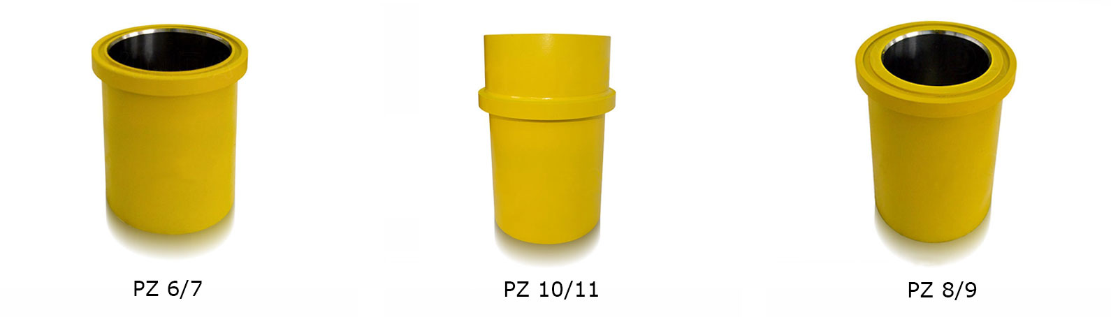
Mud Pump Spares; Mud Pump Consumables - "L" Modules - We sell high quality mud pumps spares, mud pump parts, and mud pump expendables including; mud pump liners and mud pumps pistons. They are competitively priced and have an outstanding service life. Manufactures include; Brewster, Continental Emsco, Ellis Williams, Gaso, Gardner Denver, IDECO, National, Oilwell, OPI, Wheatley, and Wilson.
Mission type mud pump liners. We are one of the few companies worldwide specializing in; and stocking “Mission” type high temperature mud pump liners. Our "Mission" type liners are formulated with two rare metals not found in common everyday liners. All of our "Mission" type mud pump liners include the seal ring and are individually packed for immediate export, offshore or domestic oilfield use. Manufactured to OEM specifications, our Mission type Discharge Module and Mission type Suction Module come complete with studs and nuts installed.
Titan Oil Tools is major supplier of expendables for mud pumps. We stock pistons, seats, valves for popular brand duplex mud pump parts and triplex mud pump parts. Call us for all your mud pump expendables.
We supply Wheatley mud pump parts, Ideco mud pump parts, Emsco mud pump spares and Gardner Denver mud pump parts and many more manufacturers. Call us for quality and the best prices.
We supply quality swabbing equipment which may include the swabbing assembly, shut-off valve on the well, also called a swabbing valve and also the lubricator. Parts may include Guiberson style oil tools replacement parts under the Titan name. Titan brand has equal specifications to Guiberson oil tools and is made in the USA. We can provide replacements for Guiberson Rope Sockets, Guiberson Hydraulic Oil Savers, Guiberson Safety Tools, Guiberson Sinker Bars, and Guiberson Tubular Jars.
Blowout preventer parts, Blowout preventer spares and blowout preventer replacement parts made in the USA. Our BOP parts , BOP spares, feature outstanding quality. We have Cameron BOP parts, Hydril BOP parts and Shaffer BOP parts.
Downhole tools for high-performance torque reduction and hole enlargement. These tools also will provide a major resistance reduction. Call us for genuine GE drilling motors, motor optimizers, mud motors, shock subs, drilling jars, downhole tool data loggers and more.
Elliott steam turbine parts have a reputation as one of the most reliable and versatile in the industry. Elliott steam turbine parts have rugged designs and are built to perform for years of reliable service. Steam turbines have extreme value and work well in a broad range of mechanical and power generation applications, around the world 24X 7 365 days per week.
OIlfield supply parts include: Hydraulic gate valves, hydraulic check valves, blowout preventer parts, BOP parts, mud pump parts, mud pump spares, drawworks parts, drawworks tubing drum, drawworks bearings, drawworks seals.
Cameron BOP parts or USA equivalents are field-replaceable and the system may be field removed change-out without removing the BOP from the stack. Call for parts needed for the BOP Stack, Choke Manifold, BOP Control Systems, and Pressure Gauges.
We sell only the best quality, high durability valve parts for Cameron Valves. All of our Cameron valve parts are made in the USA. Our valve spares offer exceptional quality and peformance.
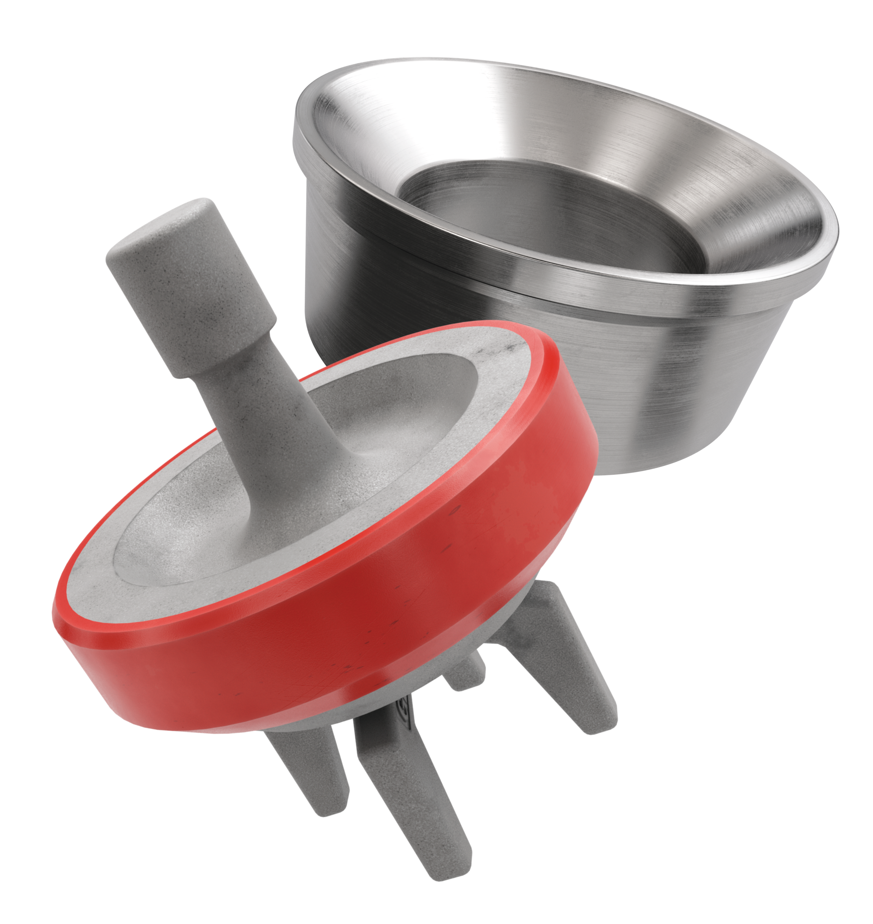
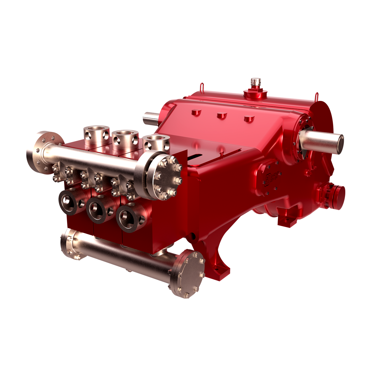
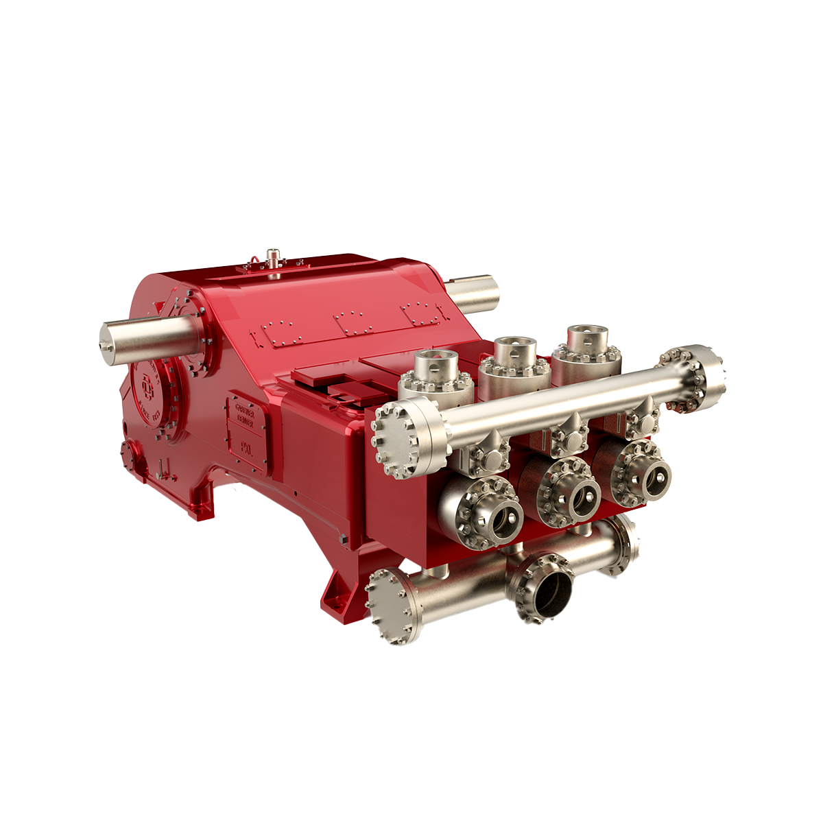
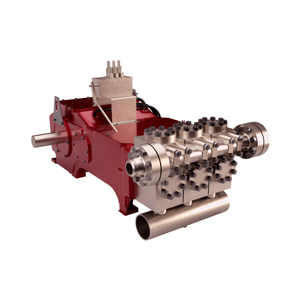
The 2,200-hp mud pump for offshore applications is a single-acting reciprocating triplex mud pump designed for high fluid flow rates, even at low operating speeds, and with a long stroke design. These features reduce the number of load reversals in critical components and increase the life of fluid end parts.
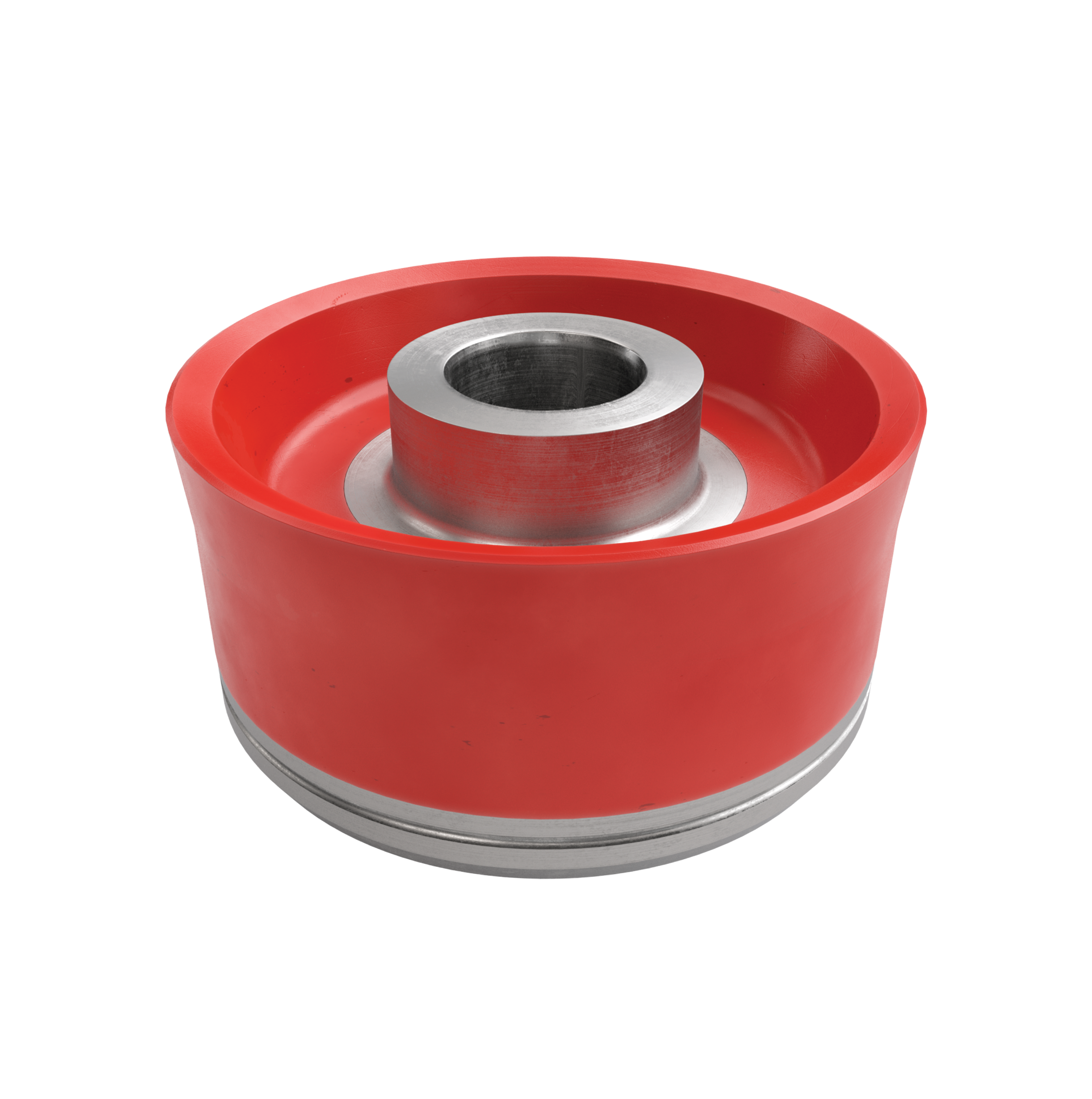
The pump’s critical components are strategically placed to make maintenance and inspection far easier and safer. The two-piece, quick-release piston rod lets you remove the piston without disturbing the liner, minimizing downtime when you’re replacing fluid parts.
This website is using a security service to protect itself from online attacks. The action you just performed triggered the security solution. There are several actions that could trigger this block including submitting a certain word or phrase, a SQL command or malformed data.
—–Liners——Mission Ceramic Liner——Mission Supreme Liner—–Piston Rods——Blak-JAK HydrA-LIGN Piston Rod System——Mission Self Aligning Piston Rod—–Pistons——Mission Green Duo Piston——Mission Slip Seal Bullitt Piston——Mission Supreme Piston——Mission Blue Lightning Piston——Mission White Lightning Bonded Piston——Mission White Lightning Slip Seal Piston—–Valves and Seats——Mission FK-1 Valve——Mission FK-N Valve——Mission Roughneck™ and Roughneck™ HP——Mission Service Master II——Mission Silver Top Valves and Seats——Mission Super Service Vavles and Seats——Service Master Drilling Valve——Supreme Valve and Seat—–Fluid End Modules and Accessories——Fluid End Accessories——-Blak-JAK Torque Pro——-Blak-JAK Torque Pro Lite——-Mission Bushing X-tractor——Liner Retention Systems——Modules (Mission L 7500 Module)—–Fluid Transfer Systems——Brine Filtration System——Centrifugal Pump Unitization Configurations——Custom Cooling Solutions——High Pressure Wash down Systems——NOV Mission Potable/Sanitary Water Pressure Sets——Resources—–Handling Tools——Adapter Rings——Air Operated Elevators——-A-Series Collar Type——-G-Series 18 Degree Center Latch——-Y-Series Slip Type——BHAT——Bushings——-Casing Bushings——-Casing Spiders——-MBH 1250——-MDSP Series——-MPCH Series——-MSPC Series——-MSP Series——-Roller Kelly Bushings——Casing Running Tools——-CRT 350 and 500 Casing Running Tool——Custom Dies and Inserts——Elevator Spiders and FMS——-BJ-250——-BJ-350——-FMS-275——-FMS-375——-V-1000——-V-500——-V-750——Hydraulic Elevators——-BX-3——BX-4-35——BX-4-50——BX-4-75——BX-5——BX-7——BXS Series——H-SJH Type——UX Horse Shoe——Links——-Perfection Links——-Weldless Links——Manual Elevators——-A-Series Collar Type——-DC Dolly——-G-Series 18 Degree Center Latch——-S-Series Auxiliary——-SBX7——-X-Series Collar Type Side Door——-Y-Series Slip Type——Manual Tongs——-HT Manual Tongs——Power Slips——-Power Slip Frame——-PS-15 Power Slip——-PS-16 Power Slip——-PS-21 Power Slip——-PS-30 Power Slip——-PF495 Power Slip——-SLT——Power Tools——-KS-6600——-KS-6800——-SSW-30——-SSW-40——-TW-61 Hydraulic Torque Wrench——Rotary Support Tables——-RST375——-RST495——-RST495 False——-RST495 Heavy——-RST495 Without Slip Ring——-RST605——-RST605 False——-RST605 Heavy——-RST605 Without Slip Ring——-RST755 Without Slip Ring——Slips——-CMS-XL——-DCS Series——-MP Series——-SD Series——-Type C——-UC-3——Resources——-BX Elevators TMS 1 of 2——-BX Elevators TMS 2 of 2——-Handling Tools TMS——-Rotary Support Table TMS—–Hoisting——Drawworks——-AHD Drawworks——–AHD-1000 Active Heave Drilling Drawworks——–AHD-1250 Active Heave Drilling Drawworks——–AHD-500 Active Heave Drilling Drawworks——–AHD-750 Active Heave Drilling Drawworks——-Drilling Drawworks——–AC Gear Driven Drawworks———ADS-10T AC Electric Gear Driven Drawworks———ADS-30Q AC Electric Gear Driven Drawworks———SSGD-1000 AC Gear Driven Drawworks———SSGD-1250 AC Gear Driven Drawworks———SSGD-360 AC Gear Driven Drawworks———SSGD-500 AC Gear Driven Drawworks———SSGD-750 AC Gear Driven Drawworks——–DC Chain Driven Drawworks———1625-UDBE DC Chain Driven Drawworks—–Iron Roughnecks——AR3200 Automated Iron Roughneck——HydraTong™ ARN-270——HydraTong™ MPT-270——Iron Roughneck Accessories——-Casing Module——-Hydraulic Mud Bucket——-Pipe Doper System——Resources——ST 100 Iron Roughneck——ST-120 Iron Roughneck——ST-160 Iron Roughneck——Jacking and Skidding——-Jacking Systems——-Jacking Claw Skidding Systems——-Rack and Pinion Skidding Systems——-Toggle Gripper System ——Lifting and Handling——-Market Segments——–Construction———SUBSEA CONSTRUCTION VESSEL———PIPELAY AND CABLELAY VESSEL———WINDMILL INSTALLATION VESSEL———CRANE VESSEL/ LIFT BOAT———IMR / WELL INTERVENTION VESSEL———ANCHOR HANDLING VESSEL——–Drilling———DRILLSHIP———JACK UP———SEMI SUBMERSIBLE———-FPSO/FPS———-SEMI SUBMERSIBLE/ SPAR/ TLP———-JACKET/ FIXED INSTALLATION——–Production———-FPSO/FPS———-SEMI SUBMERSIBLE/ SPAR/ TLP———-JACKET/ FIXED INSTALLATION——-Product Catalogue——–Anchor Handling Systems———Anchor Handling and Towing Winch———Anchor Handling Equipment Package———Secondary Winch——–Cranes———Next Generation Subsea Knuckle Boom Cranes———Box Boom Cranes———-Knuckle Boom Crane———-Single Boom Crane———-Telescopic Boom Crane———Lattice Boom Cranes———-Around the Leg Crane———-DNS Crane———-MSB Crane———-OC L Crane———-Unit Crane———Heavy Lift Cranes———-Around the Leg Crane———-MSB Crane———-Post Crane———-Tub Mounted Crane———Other Cranes———-A-Frame———-Stevedoring Cranes———Subsea Cranes———-Subsea Box Boom Crane———-Subsea MSB Crane——–Hose Loading Stations——–Mooring Systems———Mooring System for Drilling Units———Mooring System for Production Units——–Pipe Lay and Cable Lay Systems———Cable Lay Systems———Pipe Lay Systems———Tensioner———Upending Control Systems——–Riser Pull In Systems——Motion Compensation——-Crown Mounted Compensators (CMC)——-Direct Line Compensators (DLCs)——-Drill String Compensators (DSCs)——-N-Line Tensioner system——-Resources——-Tensioners——Offshore Units——-Drillship——-Fixed Platforms——-Jackup Rig——-Semi-submersible——-Well Intervention——Pipe Handling——-Horizontal Pipe Handling——–Catwalk Machines——–Catwalk Shuttle——–Pipe Deck Machines (PDM)——–Pipe – Riser Gantry Cranes——–Pipe Transfer Conveyor (PTC)——–PipeCat™ Laydown System——–Robotic Arms———DFMA-P——–DFMA-U——–UHT——-Horizontal-To-Vertical Pipe Handling——–Custom Dies and Inserts——–Hydraulic Mousehole——–Service and Access Baskets——-Pipe Handling Accessories——-Pipe Handling Cranes——-Resources——-Vertical Pipe Handling——–Racking Systems———PRS 4i/HR III———PRS5,6/HR IV———PRS8i and Hydraracker XY (HRXY)——–Standguard——Power Systems——-Hydraulic Power Units——-Motors——-Resources——-Energy Recovery——–Rotary Tables——Rotating Equipment——Structures——-Derricks——Top Drive Systems——-Fixed Electric Top Drives——-Resources——-Washpipe Systems
Technical Specification Pre-Shipment And Storage PS-4030 02 Preservation For New-Build NOV Triplex Mud Pumps
Product Information Bulletin Triplex Mud Pumps Power 01-05-01-MP 06 End Lubrication Oil Additive and wear-in Period
RIG/PLANT REFERENCE REFERENCE DESCRIPTION Triplex Mud PumpADDITIONAL CODE SDRL CODE TOTAL PGS This document contains proprietary and confidential information National Oilwell Varco which belongs to National-Oilwell Varco, L.P., its affiliates orREMARKS subsidiaries (all collectively referred to hereinafter as "NOV"). It is loaned for limited purposes only and remains the property of NOV. 11000 Corporate Centre Drive Reproduction, in whole or in part, or use of this design or Suite 200MAIN TAG NUMBER DISCIPLINE distribution of this information to others is not permitted without the Houston, Texas 77041 express written consent of NOV. This document is to be returned to NOV upon request and in any event upon completion of the use for U.S.A.CLIENT PO NUMBER which it was loaned. This document and the information contained and represented herein is the copyrighted property of NOV. Phone: +1-281-854-0400 National Oilwell Varco Fax: +1-281-854-0607CLIENT DOCUMENT NUMBER DOCUMENT NUMBER REV
This specification covers the preservation and storage procedure for shipment of new-build NOV Triplex Mud Pumps shipped from the manufacturing plant.
This specification is intended to provide preservation of new-build NOV Triplex Mud Pumps for six (6) months from the shipment of the mud pump from the manufacturing facility. If a pump is to be stored for a period of time exceeding six (6) months, additional precautions should be taken as outlined in this specification.
National Oilwell Varco recommends that all pumps are inspected for any signs of corrosion and for proper preservation at a minimum every three (3) months for pumps stored outside and every six (6) months for pumps stored indoors.
Drain all water and clean out liner wash tank. Remove drain plug in bottom of liner wash pump and drain water then reinstall plug. Remove discharge flange from liner wash pump and pour one (1) pint of inhibiting oil-based concentrate (Cortec VpCI 329 Vapor Corrosion Inhibiting oil-based concentrate or equivalent) into liner wash pump. Rotate two (2) revolutions by hand to distribute the product. Re-install discharge flange.
Drain all oil from pump power end sump and remove crosshead covers and inspection covers. Clean out oil sump as per National Oilwell PS-3081 (Mud Pump Cleanliness). Spray all internal machined parts of power end and crosshead area with inhibiting oil-based concentrate (Cortec VpCI 329 Vapor Corrosion Inhibiting oil-based concentrate or equivalent). Rotate pump turn and re-spray. Pour quantity of inhibiting oil-based concentrate specified in the table below into power end sump.
Mud Pump Models Quantity of Inhibitor 14P, FC 2200 5 Gallons 12P, 10P, HD or A1700/1400PT, FB/FC/FD 1600, FB 1300 3 Gallons 9P, 8P, B or A850-1100PT, F/FD 1000, F 800 2 Gallons 7P, A600PT, FD 500 1 Gallon
For pumps equipped with chain drives, spray internal machined parts inside chain cases with inhibiting oil-based concentrate (Cortec VpCI 329 Vapor Corrosion Inhibiting oil based concentrate or equivalent).
Remove fluid end valve covers, seals, valves springs and seats and treat internal cavities of fluid ends, discharge manifold, discharge strainer block and suction manifold with rust preventative (CRC SP400 or equivalent). Coat threads with anti-seize (KOPR KOTE 10002 or equivalent) and coat bottom side of valve cover with rust preventative. Reinstall seals and fluid end valves covers hand tight. Customer liners, pistons, piston rods, valves, seats, springs and liner retention parts are not used for plant testing. These expendables are checked for preservation when packed and then shipped with the loose parts.
Remove breather and pack with loose parts for later shipment with pump. Seal breather hole with a greased solid plug. Affix a warning label near the breather opening (see Exhibit 1).
Spray all machined unpainted loose parts and expendables to be shipped with pump with rust preventative (CRC SP400 or equivalent). All parts will be wrapped or boxed to prevent damage.
Affix one (1) warning label (see Exhibit 2) to the power end pump cover and one (1) warning label on the fluid end assembly of the pump. Affix warning labels on each loose part container. In cases where the equipment will be boxed at an offsite export packer, a sufficient number of warning labels will be supplied with the shipment.
Indoor storage is preferred whenever possible; but if outside storage is required, ensure pump is stored away from salt water spray, sand blast or other adverse conditions. It is highly recommended that ship loose parts be stored indoors to eliminate conditions that promote condensation and direct sources of moisture.
Note: It is recommended that inspections be carried out on six (6) month cycles when pumps are in indoors and three (3) month cycles when stored outside.
Any pump that has been in storage will need a thorough inspection prior to start-up to insure it has not been damaged in any way and that all parts are properly in place. Failure to observe the following points can result in serious damage. Before servicing the pump, the power end sump and chain drives housings will need to be drained of any inhibiting additive. The Cortec brand products used for preservation are compatible with all lubricating oils and need not be totally removed when putting equipment into service.
To service the Fluid End after storage and prior to start-up, remove covers and thoroughly clean and inspect inside of the fluid end cylinders. Properly install valves, pistons, liners and all other fluid end parts. Carefully tighten all bolts, nuts, studs and working connections to specified torque requirements.
www.nov.com DOCUMENT OR DRAWING NO. PAGE 1 of ENGINEERING EDN-1688 12SUBJECT COMMISSIONING PROCEDURE, FB/FD-1600 APPROVED REVISED DATE REV.
TRIPLEX MUD PUMP GDH 02PREPARED BY DATE CHECKED BY DATE
DOCUMENT TITLE: Commissioning Procedure, FB/FD-1600 Triplex Mud Pump DOCUMENT OR DRAWING NO. PAGE 2 of ENGINEERING EDN-1688 12SUBJECT COMMISSIONING PROCEDURE, FB/FD-1600 APPROVED REVISED DATE REV.
TRIPLEX MUD PUMP GDH 02PREPARED BY DATE CHECKED BY DATE
1. Power End.................................................................................................. 3 2. Main Electric Drive Motors 3 3. Auxiliary A/C Motors. 4 4. Instrumentation........................................................................................... 4 5. Liner Wash System..................................................................................... 4 6. Fluid End.................................................................................................... 4 7. Suction Dampener/Desurger....................................................................... 4 8. Pulsation Dampener.................................................................................... 4 9. Pressure Gauge............................................................................................ 5 10. Reset Relief Valve....................................................................................... 5 11. Discharge Strainer 5 12. Mud Pump Drive Assembly. 5 a. Belt Drive Units 5 b. Chain Drive Units. 5
1. Pre-Commission Checks.. 6 2. Commissioning Operational Test. 8 3. Inspections/Check-Offs during Test Program.. 9 DOCUMENT OR DRAWING NO. PAGE 3 of ENGINEERING EDN-1688 12SUBJECT COMMISSIONING PROCEDURE, FB/FD-1600 APPROVED REVISED DATE REV.
TRIPLEX MUD PUMP GDH 02PREPARED BY DATE CHECKED BY DATE
The initial startup procedures are written to assist the operator in preparing the pump packages for normaloperation. The startup procedures are separated into two categories: Part I: Pre-Commissioning, and PartII: Commissioning Procedures. It is suggested that a copy of these pages be made for each pump to beused as a check-off sheet.
Note: The rust preventative on the internal surfaces of the pump is oil-soluble and is compatible with the lubricants recommended above. It is not necessary to flush and drain unless the preservative has become contaminated (water, sand etc.).
Megger test the motors. Check each motor separately for the correct rotation. Reconnect if necessary. Megger test the blower motors. Check blower motors for correct rotation and quantity of air flow. DOCUMENT OR DRAWING NO. PAGE 4 of ENGINEERING EDN-1688 12SUBJECT COMMISSIONING PROCEDURE, FB/FD-1600 APPROVED REVISED DATE REV.
TRIPLEX MUD PUMP GDH 02PREPARED BY DATE CHECKED BY DATE
Clean liner wash tank, if needed, and fill with fresh clean water. Ensure that supply hoses and spray nipples are installed correctly. Start pump and adjust regulating valve to maximum flow without splash onto the extension rods.
Check to assure that all liners, valves, and pistons are installed properly in accordance with the installation instructions. Ensure that the liner end covers are installed on the rear end of the liners. Ensure that the baffle discs are installed on the end of the crosshead extension rods. Clean grease and paint from the exposed parts of the extension rods, checking for burrs. Coat rods with a light oil.
NOTE: When charging the bladder, make sure that the mud pump suction line valve has been closed and that all pressure has been bled off of the suction manifold surrounding the suction desurger
If a dampener is used, charge dampener with a hand-operated air pump to 10 PSI (0.7 bar). Once pump operations have been started, check the operation of the suction dampener by inspecting the sight glass. Add or release air pressure through the Shraeder valve to keep the diaphragm between the midpoint and the bottom of the sight glass.
Refer to manufacturers instructions for charging the dampener. USE ONLY NITROGEN OR AIR! DO NOT USE OXYGEN. DOCUMENT OR DRAWING NO. PAGE 5 of ENGINEERING EDN-1688 12SUBJECT COMMISSIONING PROCEDURE, FB/FD-1600 APPROVED REVISED DATE REV.
TRIPLEX MUD PUMP GDH 02PREPARED BY DATE CHECKED BY DATE
Check the installation and the setting. NO SHUT-OFF VALVE is to be between the pump discharge and the relief valve. Ensure that piping from the discharge port goes directly to the mud tank/pit and is securely tied down, with a minimum downward slope of 1/4 per foot. Ensure that piping has pressure rating equal to the relief valve highest setting.
Remove the strainer screen from the housing and assure that it is clean and free from obstructions. Check the stud nuts for proper make-up torque.
Check the chain guards to ensure that the chains will not drag on the guard. Check the oil pump to ensure that the relief valve is installed on the suction side. Start the pump and ensure that the spray nozzles are spraying oil over the full width of the chain. Adjust the relief valve to 15-25 PSI output with the warm oil. DOCUMENT OR DRAWING NO. PAGE 6 of ENGINEERING EDN-1688 12SUBJECT COMMISSIONING PROCEDURE, FB/FD-1600 APPROVED REVISED DATE REV.
TRIPLEX MUD PUMP GDH 02PREPARED BY DATE CHECKED BY DATE
The power end and the fluid end have gone through rigorous tests prior to being shipped from the manufacturing site; therefore, the following recommendations for the commissioning test are made for the purpose of checking the overall unitization functions, including instrumentation, and to assure that there are no problems which may have occurred during transportation and storage.
Operation of the pump in parallel to check the SCR-Motor assignments and controls, volumetric displacement and mudline systems are at the option of the purchaser.
Check the discharge mudline to assure that all necessary valves are open. Ensure that the mud tanks are full of test fluid (mud/water) prior to startup.
Make the desired assignment of the SCR-Motor Control System to the pump motors, and open the throttle slightly. Check to ensure that charge pump and liner wash motors have started.
If no immediate problems are encountered, slowly throttle the pump to approximately 60 SPM and continue operating the mud pump while making the following inspections to assure that all systems are working properly:
4) Check for interference or dragging in the belt/chain drive assemblies. DOCUMENT OR DRAWING NO. PAGE 7 of ENGINEERING EDN-1688 12SUBJECT COMMISSIONING PROCEDURE, FB/FD-1600 APPROVED REVISED DATE REV.
TRIPLEX MUD PUMP GDH 02PREPARED BY DATE CHECKED BY DATE
Pump A/C motor operating properly. Valves open for the proper volume of drilling fluid. Gauges/controls functioning properly.
Check the valve for proper relief setting. The valve should be set 10% above the pressure rating for the liner size being used. Refer to the nameplates on each side of the pump or the pump datasheet to obtain the operating pressure for that particular size liner. DOCUMENT OR DRAWING NO. PAGE 8 of ENGINEERING EDN-1688 12SUBJECT COMMISSIONING PROCEDURE, FB/FD-1600 APPROVED REVISED DATE REV.
TRIPLEX MUD PUMP GDH 02PREPARED BY DATE CHECKED BY DATE
The following are basic guidelines for conducting of an eight (8) hour operational test. The pump was test run under pressure in the manufacturing plant but with different motors and drives.
RATED LINER PRESSURE*...180 min. @ 100 SPM _______ _______ * Not to exceed pressure rating of fluid end. DOCUMENT OR DRAWING NO. PAGE 9 of ENGINEERING EDN-1688 12SUBJECT COMMISSIONING PROCEDURE, FB/FD-1600 APPROVED REVISED DATE REV.
TRIPLEX MUD PUMP GDH 02PREPARED BY DATE CHECKED BY DATE
The overall performance of the unitized pump package should be continuously monitored during the eight hour test program. The following checks should be made and recorded each two hours of operation.
LOAD SHARE (YES/NO).. ______ _____ _____ _____ _____ DOCUMENT OR DRAWING NO. PAGE 10 of ENGINEERING EDN-1688 12SUBJECT COMMISSIONING PROCEDURE, FB/FD-1600 APPROVED REVISED DATE REV.
TRIPLEX MUD PUMP GDH 02PREPARED BY DATE CHECKED BY DATE
SUCTION MANIFOLD PRESS. ______ _____ _____ _____ _____ DOCUMENT OR DRAWING NO. PAGE 11 of ENGINEERING EDN-1688 12SUBJECT COMMISSIONING PROCEDURE, FB/FD-1600 APPROVED REVISED DATE REV.
TRIPLEX MUD PUMP GDH 02PREPARED BY DATE CHECKED BY DATE
_____________________________________________________________________________________ DOCUMENT OR DRAWING NO. PAGE 12 of ENGINEERING EDN-1688 12SUBJECT COMMISSIONING PROCEDURE, FB/FD-1600 APPROVED REVISED DATE REV.
TRIPLEX MUD PUMP GDH 02PREPARED BY DATE CHECKED BY DATE
Triplex Mud Pump For Models: FD-500, FD-800, FD-1000 & FD-1600
RIG/PLANT REFERENCE REFERENCE DESCRIPTION Triplex Mud PumpADDITIONAL CODE SDRL CODE TOTAL PGS This document contains proprietary and confidential information National Oilwell VarcoREMARKS which belongs to National Oilwell Varco; it is loaned for limited 1530 W Sam Houston Pkwy. N purposes only and remains the property of National Oilwell Varco. Reproduction, in whole or in part; or use of this design or Houston, TX 77043MAIN TAG NUMBER DISCIPLINE distribution of this information to others is not permitted without the Phone 713-935-8000 express written consent of National Oilwell Varco. This document is Fax 713-935-8382 to be returned to National Oilwell Varco upon request and in anyCLIENT PO NUMBER event upon completion of the use for which it was loaned. National Oilwell VarcoCLIENT DOCUMENT NUMBER DOCUMENT NUMBER REV
All specifications are in accordance with Engineering designs and should be adhered to in allrepairs. Operation and maintenance information on equipment other than National Oilwell Varcosis taken in part from the various manufacturers manuals. If the equipment manufacturers issuelater instructions, or in the event of conflict, the manufacturers information will take precedenceover that shown in this manual, unless specifically stated otherwise.
When operating all mechanical and electrical equipment, all safety devices must beengaged, properly adjusted, and in good operating condition, including overtravel devicesfor traveling blocks, warning or shutdown devices for engines, etc.
PREFACE.................................................................................................................................... 31 INSTALLATION OF NEW PUMP ................................................................................... 112 SETTING THE PUMP ..................................................................................................... 11 2.1 Land Installations.................................................................................................. 113 SUCTION SYSTEM REQUIREMENTS........................................................................... 16 3.1 Caution ................................................................................................................. 164 PREPARATION OF POWER END ................................................................................. 17 4.1 Power End Lubrication.......................................................................................... 17 4.2 Installation of Crosshead Extension Rods and Diaphragm Stuffing Box Seals..... 185 PISTON AND LINER COOLING SYSTEM ..................................................................... 19 5.1 Stationary spray (View A, Fig. 6) .......................................................................... 20 5.2 Moving Nozzle ...................................................................................................... 206 ASSEMBLY OF FLUID END PARTS ............................................................................. 23 6.1 Valves and Seats.................................................................................................. 237 FD-500, FD-800 & FD-1000............................................................................................ 24 7.1 Liners.................................................................................................................... 25 7.2 Piston Rod ............................................................................................................ 25 7.3 Piston Rod Clamps ............................................................................................... 25 7.4 Liner Cage and Lower Valve Guide ...................................................................... 26 7.5 Cylinder head ....................................................................................................... 26 7.6 Discharge Valve Pot Covers ................................................................................. 268 FD-1600 .......................................................................................................................... 27 8.1 Liner...................................................................................................................... 28 8.2 Piston Rod ............................................................................................................ 28 8.3 Piston Rod Clamps ............................................................................................... 29 8.4 Lower Valve Guide and Cylinder Head................................................................. 29 8.5 Discharge Valve Pot Covers ................................................................................. 29 8.6 Discharge Manifold all models .............................................................................. 30
Your National Oilwell Varco pump has been completely assembled and test operated under pressure before being shipped to the field. Unless otherwise instructed, the lubrication is drained from the power end and the expendable parts are removed from the fluid end. Before putting the pump into service, the following precautions and operations must be performed or checked.
2 SETTING THE PUMP The skids under the National Oilwell Varco pumps are suitable for most any type of installation. It should be noted, however, that the box type construction of the power frame has high resistance to bending but relatively less resistance against twist. Therefore, the support under the pump must be level and adequate to support the weight and operating forces exerted by the pump.
2.1 Land Installations In land installations, a mat of 3 X 12 (76.20 mm x 304.8 mm) boards laid side crosswise to the pump skids for the entire length, or at a minimum, at the points indicated in Fig. 2, is usually sufficient. The boards should be a few feet wider than the width of the pump skid runners. Wet or marshy locations may require a more stable foundation.
Suitable means, such as National Oilwell Varco pump spacers as shown in Fig. 3, should be used to keep the pump anchored and the drive in alignment. National Oilwell Varco mud pump spacers provide 8-1/2 (215.9mm) adjustment. Any desired length may be obtained by lengthening the standard pipe spacer, which is made of 3 (76.20mm) extra strong pipe.
2.1.1 Permanent Installations On permanent installations such as barge, platform, structural base, or concrete slab, where pump skids are bolted down, it is essential that the skids be properly shimmed to prevent possibility of twisting or distorting the power frame. The pump skids must sit solid on all shim points with bolts loose.
On barge installations, the pump skids are generally bolted down to T-beams running parallel and in line with the pump skids. Install shims at points shown in Figs. 2 and 4 and observe caution of proper shimming to prevent twist or distortion.
On installations where the power unit or electric motor is mounted integrally with the pump skids, the preferred installation would be to set the pump package on the T-beam skids and provide retention blocks rather than bolts to hold it in place. This will allow the pump to float and minimize the transfer of barge deck or platform distortion into the frame.
2.1.2 Installation of the Drive The drive between the mud pumps and the power source, whether V-belts or multi-width chains, should be installed with the greatest care to assure maximum operating life with minimum of unexpected or undesirable shutdowns due to drive failures.
When installing the drive sheave or sprocket, make sure all grease or rust preventative is removed from the shaft and the bore of the drive. Remove all burrs or rough spots from the shaft, key, and keyway. Fit key to the keyways in both the shaft and drive and install key into shaft keyway.
The final alignment of the V-belt sheaves should be checked after the V-belts have been installed and adjusted to their operating tension. If the sides of the sheaves are of equal distance from the centerline of the groove, check alignment by stretching TWO strings (fish line or piano wire preferred) along one side of the two sheaves, one above and one below the centerline, and moving one of the sheaves until the strings touch four points on the side of the sheave rims. This will determine that the centerline of the drives are parallel and the faces of the sheaves are square.
Adjust the belt tension by moving the sheaves apart until all of the sag has just been eliminated from the tight side of the belt and some of the belts on the slack side. Then increase the centers approximately (13mm) for each 100 (2540 mm) center distance. Example: On 150 (3810 mm) center, move pump an additional (19.5 mm).
DO NOT OBTAIN BELT TENSION BY PICKING UP END OF PUMP AND ALLOWING BELTS TO TIGHTEN UNDER WEIGHT OF PUMP AS END IS BEING LOWERED TO THE GROUND.
Proper installation and maintenance of the sprocket and chain drives are essential if good service life is to be obtained. Since many factors, such as chain width, center distances, speeds, and loads must be considered when determining the allowable tolerance for sprocket alignment, no good rule of thumb can be applied. The chain alignment must simply be held as nearly perfect as possible. A more precise alignment can be made by stretching two steel wires (piano wire) along one face of the two sprockets, one above and one below the centerline, and moving one of the sprockets until the wires touch at four points. This will determine that the centerlines of the drives are parallel and the faces of the sprockets are square.
The pump drive chain lubrication system on the majority of National Oilwell Varco pumps is an independent system having its own oil pump, reservoir, and drive. Fill chain case to the indicated level with a non-detergent oil as follows:
- Daily check of oil level. - Daily check on condition of oil. - Frequent check on oil pressure. (5-15 psi) (.352 - 1.06 kg/cm) - Volume of oil being applied to chain. - Condition of nozzles in spray tube. - Condition of oil pump drive (V-belts or chain)
NOTE: Oil pressure may be adjusted with the pressure relief adjusting screw on the rear of the pump housing. Pressure drops may also indicate suction and discharge filter screens need cleaning.
3 SUCTION SYSTEM REQUIREMENTS Individual installation conditions will dictate the design of the suction system. The suction of the FD-series pumps must have a positive head (pressure) for satisfactory performance. The optimum suction manifold pressure is 20-30 psi (1.75-2 kg/cm) for maximum volumetric efficiency and expendable parts life. This head pressure is best supplied by a 5 x 6 centrifugal pump with 40 h.p. 1150 rpm electric motor. This type of drive requires a device to automatically start and stop the centrifugal pump motor simultaneously with the triplex pump. On DC electric powered rigs a signal can usually be supplied from the DC control panel to energize a magnetic starter when the mud pump clutch air line will provide a set of contacts for energizing the magnetic starter when clutch is engaged.
The charging pump can also be belt driven from the triplex pinion shaft charging type of drive is not as efficient at slow speeds with viscous fluids.
Under some conditions the FD-Series pumps may be operated without a charging pump, provided the fluid level in mud pits is higher than the top of the liners, fluid being pumped is low viscosity and suction line must be short, straight and of at least the same diameter as suction manifold inlet.
The suction lines should be piped with valve arrangements so the charging pump can be by-passed so operation can be continued in event of charging pump failure or for maintenance. Operation without a charging pump can be improved by replacing the suction valve springs with a weaker spring.
Suction desurgers are a very effective aid for complete filling of the liners and dampening pulsations in the suction line which results in a smoother flow in the discharge line. If your pump is equipped with a suction desurger it must be pre-charged with compressed air before operations are begun. See suction desurger manual for charging instructions.
3.1 Caution Do not pipe the return line from the shear relief valve back into the suction system as a relief valve operation will cause a sudden pressure rise in the system vastly greater than the system pressure ratings, resulting in damage to manifold, suction desurger and centrifugal pump.
4 PREPARATION OF POWER END Your National Oilwell Varco pump has been completely assembled and test operated before being shipped to the field. Unless otherwise instructed, the lubrication is drained from the power end, and the expendables are removed from the fluid end for storage protection. Before operating the pump, the following must be performed or checked:
Before installing lubricant, open inspection door in cover and check oil reservoir for possible accumulation of condensation, etc., and drain and flush by removing the pipe plugs on each side of the pump.
Add the proper type and quantity of lubrication in the power end. Refer to the Lubrication Section of this manual, or lubrication plate on pump frame for type and quantity required.
Recheck oil level after pump has operated for a period of 15 minutes. Shut pump down and allow approximately five minutes for the oil level to equalize. Check at oil level gauge, Item 1, Fig. 1. It is usually necessary for a few more gallons of oil to be added due to a certain amount being retained in the crosshead area and frame cavities.
With reference to Figure 5, remove the diaphragm stuffing box and plate (1) and rotate pump so that crosshead is at the front of the stroke. Thoroughly clean the front of the crosshead and the face of the crosshead extension rod. Insert alignment boss on crosshead extension rod into the crosshead bore and tighten the retainer bolts (2) to the following torque. Safety wire bolt heads.
a. Remove pressure spring (5) from single lip oil seal (6) and place seal in the inner (power end) p


 8613371530291