
triplex mud pump calculation manufacturer

Rig pump output, normally in volume per stroke, of mud pumps on the rig is one of important figures that we really need to know because we will use pump out put figures to calculate many parameters such as bottom up strokes, wash out depth, tracking drilling fluid, etc. In this post, you will learn how to calculate pump out put for triplex pump and duplex pump in bothOilfield and Metric Unit.

Continental Emsco Drilling Products, Inc., which consisted of Emsco drilling machinery and Wilson mobile rigs, was purchased by National-Oilwell, Inc on July 7, 1999. To our knowledge, no pumps have been manufactured and sold under the Emsco brand name since National-Oilwell acquired them.
Fairbanks Morse pumps are currently manufactured in Kansas City, Kansas. Fairbanks Morse is a division of Pentair ever since August, 1997 when Pentair purchased the General Signal Pump Group.
Gaso pumps are manufactured by National Oilwell Varco. Gaso was acquired as "Wheatley Gaso" by National-Oilwell in the year 2000. At the time, Wheatley Gaso was owned by Halliburton.
Skytop Brewster pumps are no longer available as new pumps. Skytop Brewster(Cnsld Gold), a unit of Hansen PLC"s Consolidated Gold Fields subsidiary, was acquired while in bankruptcy by National-Oilwell, Inc. in November, 1999.

Pump Output per Stroke (PO): The calculator returns the pump output per stroke in barrels (bbl). However this can be automatically converted to other volume units (e.g. gallons or liters) via the pull-down menu.
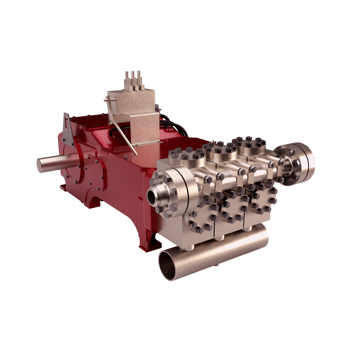
A triplex mud (or slush) pump has three horizontal plungers (cylinders) driven off of one crankshaft. Triplex mud pumps are often used for oil drilling.

Oil and Gas drilling process - Pupm output for Triplex and Duplex pumpsTriplex Pump Formula 1 PO, bbl/stk = 0.000243 x ( in) E.xample: Determine the pump output, bbl/stk, at 100% efficiency for a 7" by 12". triplex pump: PO @ 100%,= 0.000243 x 7 x12 PO @ 100% = 0.142884bbl/stk Adjust the pump output for 95% efficiency: Decimal equivalent = 95 + 100 = 0.95 PO @ 95% = 0.142884bbl/stk x 0.95 PO @ 95% = 0.13574bbl/stk Formula 2 PO, gpm = [3(D x 0.7854)S]0.00411 x SPM where D = liner diameter, in. S = stroke length, in. SPM = strokes per minute Determine the pump output, gpm, for a 7" by 12". triplex pump at 80 strokes per minute: PO, gpm = [3(7 x 0.7854) 1210.00411 x 80 PO, gpm = 1385.4456 x 0.00411 x 80 PO = 455.5 gpm
Example:Duplex Pump Formula 1 0.000324 x (liner diameter, in) x ( stroke lengh, in) = ________ bbl/stk -0.000162 x (rod diameter, in) x ( stroke lengh, in) = ________ bbl/stk Pump out put @ 100% eff = ________bbl/stk Example: Determine the output, bbl/stk, of a 5 1/2" by 14" duplex pump at 100% efficiency. Rod diameter = 2.0": 0.000324 x 5.5 x 14 = 0.137214bbl/stk -0.000162 x 2.0 x 14 = 0.009072bbl/stk Pump output @ 100% eff. = 0.128142bbl/stk Adjust pump output for 85% efficiency: Decimal equivalent = 85 100 = 0.85 PO@85%)= 0.128142bbl/stk x 0.85 PO@ 85% = 0.10892bbl/stk Formula 2
PO. bbl/stk = 0.000162 x S[2(D) - d] where S = stroke length, in. D = liner diameter, in. d = rod diameter, in. Example: Determine the output, bbl/stk, of a 5 1/2". by 14". duplex pump @ 100% efficiency. Rod diameter = 2.0in.: PO@100%=0.000162 x 14 x [ 2 (5.5) - 2 ] PO @ 100%)= 0.000162 x 14 x 56.5 PO@ 100%)= 0.128142bbl/stk Adjust pump output for 85% efficiency: PO@85%,= 0.128142bb/stkx 0.85 PO@8.5%= 0.10892bbl/stk Metric calculation Pump output, liter/min = pump output. liter/stk x pump speed, spm. S.I. units calculation Pump output, m/min = pump output, liter/stk x pump speed, spm. Mud Pumps Mud pumps drive the mud around the drilling system. Depending on liner size availability they can be set up to provide high pressure and low flow rate, or low pressure and high flow rate. Analysis of the application and running the Drill Bits hydraulics program will indicate which liners to recommend. Finding the specification of the mud pumps allows flow rate to be calculated from pump stroke rate, SPM. Information requiredo Pump manufacturer o Number of pumps o Liner size and gallons per revolution Weight As a drill bit cutting structure wears more weight will be required to achieve the same RoP in a homogenous formation. PDC wear flats, worn inserts and worn milled tooth teeth will make the bit drill less efficiently. Increase weight in increments of 2,000lbs approx. In general, weight should be applied before excessive rotary speed so that the cutting structure maintains a significant depth of cut to stabilise the bit and prevent whirl. If downhole weight measurements are available they can be used in combination with surface measurements to gain a more accurate representation of what is happening in the well bore.

Pump OutputDuplex Pump OutputLitres/Stroke @ 90% Efficiency (2” Rod Diameter)Liner Diamerter (mm)StrokeLength(mm)101 108 114 121 127 133 140 146 152 159 165 170 178 184 190 197 203 209 216203 5.40 6.19 6.99 7.78 8.73 6.69 10.6 11.5 12.7 13.8 15 16.2 17.4 18.9254 6.67 7.62 8.58 6.69 10.8 12.0 13.3 14.6 15.9 17.3 18.7 20.0 21.9 23.6305 7.78 9.90 10.10 11.40 12.9 14.3 15.9 17.3 19.1 20.7 22.6 24.3 26.2 28.3 30.4356 14.6 16.4 18.0 19.9 21.8 23.8 25.9 28.0 30.2 32.4 35.0 37.4 39.9381 15.6 17.3 19.2 21.1 23.2 25.3 27.5 29.7 32.3 34.7 37.4 39.9 42.8406 16.7 18.6 20.5 22.6 24.8 27.0 29.4 32.3 34.5 37.0 39.7 42.8 45.6 48.6457 18.4 20.7 22.7 25.3 27.8 30.2 32.7 35.6 38.5 41.3 44.5 47.7 51.1 54.4508 20.3 22.7 25.1 28.0 30.5 33.4 36.4 39.4 46.2 45.9 49.4 53.1 56.8 60.4559 49.8 53.5 57.3 61.1 65.1 69.2 73.5610 71.1 75.6 80.2Note: For pump output in m 3 /stroke, move the decimal point 3 places to the left.Duplex Mud PumpsThe pistons on a duplex mud pump work in both directions, so that the rear cylinder has thepump rod moving through its swept volume and occupying some volume. The difference incalculations for a duplex vs. a triplex pump is that the displacement volume of this pump rodmust be subtracted from the volume in one of the cylinders, plus the difference in number ofpumping cylinders; 4 for a duplex and 3 for a triplex. Duplex pumps generally have longerstrokes (in the 10 to 18 in. range) and operate at lower rate; in the 40 to 80 stroke/minrange.The general equation to calculate output of a duplex pump is:Pump output (litres/stroke) = ,Where:ID = ID of the linerOD = OD of the rodL = Length of the pump strokeEff = Pump efficiency (decimal)1800, 505 – 3 rd Street SW Calgary, Alberta, Canada T2P 3E6 Telephone: 403.547.2906 Fax: 403.547.3129Email: info@hitechfluid.com Web: www.hitechfluid.com
This application claims the benefit of Provisional U.S. Patent Application No. 62/655,927, filed Apr. 11, 2018, and entitled “SYSTEM AND METHODS FOR NON-INVASIVE PUMP STROKE, RPM AND PUMP HEALTH DETECTION” the entire content and disclosure of which, both express and implied, is incorporated herein by reference. FIELD OF THE INVENTION
The present invention relates to apparatus and methods for monitoring pumps, and in particular, positive displacement triplex pumps. BACKGROUND OF THE INVENTION
Positive displacement pumps are used in oil fields to circulate high volumes of drilling fluid/mud under high pressure down the drill string and back up the annulus. There are two common types of positive displacement pumps: duplex pumps and triplex pumps. Duplex pumps have two pistons while triplex pumps have three pistons that move back and forth in liners.
Triplex pumps have three intake valves and three discharge valves. The three pistons in triplex pumps can be moved back, also called back stroke, to pull in drilling mud through open intake valves on the same side of the piston. When the pistons are moved forward, also called forward or discharge stroke, the drilling fluid is pushed out through open discharge valves on the same side of the piston and down a discharge line. Due to this, the triplex pumps are also called “single acting”.
Triplex mud pumps produce pulsating flows which lead to pressure spikes. In order to accelerate the drilling fluid to maximum velocity, each piston stroke must overcome the inertia of the columns of fluid in the suction/intake and discharge pipe work. At the end of each stroke, this inertia must again be overcome to bring the fluid columns to rest. This cycle of alternate acceleration and deceleration is the primary cause of fluid pulsations or pressure spikes.
In order to avoid these pressure spikes, the drilling industry uses pulsation dampeners or dampers. For example, a triplex pump includes a pulsation dampener in the discharge line. The pulsation dampener smooths out surges or pulses created by the pistons as they discharge mud. A pulsation dampener creates an area of low pressure in the system with enough volume to absorb the pulsation. The pulsation dampener has a membrane with a “cushion” of compressible gas/air behind it that flexes to absorb the pulse, allowing a laminar flow downstream of the dampener.
Positive displacement pumps can produce the same flow at a given speed (RPM) irrespective of the discharge pressure. However, a slight increase in internal leakage as the pressure increases prevents a substantially constant or linear flow rate.
When a triplex mud pump is in operation, the driller requires information on the amount of mud flowing down hole in order to keep the operation running at peak efficiency. Many service companies provide services related to obtaining this information. Typically, this involves monitoring the pump strokes and then calculating the flow out from the pump using a standard formula involving the pump strokes per minute and the pump volume. Electronic pump stroke counters can also assist the driller by measuring the mud pump"s strokes per minute and total strokes.
Triplex mud pumps are basic pumps with minimal technology. Current techniques for monitoring the pump strokes involve physically altering the pump. Two conventional solutions involve a C-clamp pump stroke sensor and a proximity switch sensor. Both techniques require the installer to make mechanical modifications to the triplex pump in order to install the sensors so that they can detect the piston stroke rate inside the pump. In order to install these sensors, the operator either needs to drill holes in the pumps in order to run cables or may be required to leave the lids or covers off the pump after installation.
These installation techniques have inherent risks and problems. For example, leaving the lids off can potentially cause drilling fluids to spill over or other similar safety hazards. If the spills exceed certain pre-determined limits, the operator may be required to report it to regulatory bodies, such as the United States Environmental Protection Agency. Modifying or drilling holes into existing pumps can also cause safety issues. Additionally, there is an associated cost with stopping drilling operations during such an installation. This may expose the environment and personnel to danger and can create liability for the drilling contractor as well as the operator of the oil and gas field.
Accordingly, there is a need for a non-invasive solution to measure desired pump characteristics, such as, piston strokes in triplex pumps. Ideally, such a solution should also monitor the speed (PRM) and health of the pump and valves. SUMMARY OF THE INVENTION
According to an embodiment, an apparatus for detecting a characteristic of a pump includes: a housing having a first planar surface and a second planar surface opposite the first planar surface, a mount structure located on the second planar surface, wherein the mount structure is configured to facilitate attachment of the apparatus on an external surface of the triplex pump, and wherein the mount structure avoids penetrating an inside surface of the triplex pump. The housing is configured to enclose one or more sensors, such as, an accelerometer for detecting the pump characteristic. In one or more embodiments, the pump is a triplex pump having three cylinders. The mount structure can be a magnet or a similar coupling device for affixing the apparatus to a metal pump. The magnet facilitates a non-intrusive detection of the pump characteristic. The non-intrusive detection of the pump characteristic substantially eliminates production downtime at an oil rig. The housing has a third planar surface, wherein the third planar surface comprises a plurality of LED lights. At least one LED light is configured to provide an indicator of a pump characteristic, such as, the speed of rotation of the pump.
In another embodiment, a method for determining health of a triplex pump involves the steps of: providing the magnetic-base apparatus discussed above, wherein the apparatus is configured to be mounted on a pump head. The apparatus is configured to detect a first signal waveform indicative of at least one of a valve signature and a pump speed. The detected signal is input into a signal shaper circuit and a comparator circuit. The first signal is filtered to generate a second signal waveform having one or more defined peak forms. Each peak is representative of a valve signature. The method further involves putting the second signal waveform through a relay circuit to generate a third signal waveform. The relay is configured to divide the frequency of the second signal waveform by three to generate a single signal pulse representative of the speed of the pump. Each of the three waveforms is digitally transmitted to a display terminal and displayed in a single graph. The method further comprises flagging the pump for inspect when a deviance from a baseline speed is observed.
In another embodiment, a method for determining health of a triplex pump involves: providing the magnetic-base apparatus discussed above, wherein the apparatus is configured to detect one or more pump stroke signal waves, and wherein the apparatus includes a microprocessor running an algorithm for sampling detected pump stroke signal waves over a period of time or space and dividing it into one or more frequencies. This is followed by generating a graphical display of the frequencies. A first peak frequency is selected and its data is obtained from the graph. The pump stroke data can be obtained by converting the first peak frequency data into revolutions per minute (RPM). The method further comprises flagging the pump for inspect when a deviance from a predetermined baseline RPM is observed. BRIEF DESCRIPTION OF THE DRAWINGS
As shown in FIGS. 1A and 1B, an apparatus 100 is provided for detecting pump strokes. The apparatus 100 can be configured to detect pump valve and cylinder sealing health by monitoring valve noise and “valve signatures”. A set of valve positions and the corresponding signals is known as a valve signature. The apparatus 100 is also configured to non-intrusively detect pump speed in revolutions per minute (RPM). The apparatus 100 is configured as a compact and portable device that can be mounted at any location on the exterior of a pump.
The apparatus 100 includes a housing 110 having a first planar surface 120A and an opposing planar surface 120B. The housing 110 can include a metallic aluminum enclosure. The housing 110 includes a mount structure 130 located on its base or second planar surface 120B. The mount structure 130 allows for fast mounting to the exterior of metal pumps. In an exemplary embodiment, the mount structure 130 is a magnet.
A third planar surface 120C of the housing includes two LED indicators 150A, 150B. A first LED indicator 150A is configured to be illuminated when the apparatus 100 is synchronized with the signature of a pump cylinder while a second LED indicator 150B is configured to be illuminated when the apparatus 100 detects the RPM of the pump.
The housing 110 is configured to enclose one or more sensors, such as, accelerometers, vibration sensors, pressure sensors, displacement sensors and/or other sensors. The housing 110 can further include electronic circuitry, microprocessors which are configured to improve digital signal processing and firmware to process the valve signature data and pump stroke data and digitally transmit it a display unit. The housing 110 can further enclose a pulse shaper circuit and a comparator circuit to shape the raw signal detected by the apparatus 100. In some embodiments, the housing 110 can further include a divide by three relay circuit. As shown, the housing 110 can be substantially square in shape. However, in other embodiments, the housing 110 can be circular, elliptical, ovoid or any other desired shape.
In certain embodiments, the magnet 130 may include a suitable cover 135. The cover 135 is removed before the magnet 130 can be mounted or attached to metallic pumps. As shown in FIG. 1C, the apparatus 100 can be mounted on any desired location on an exterior housing of a triplex pump 140.
Conveniently, since the apparatus 100 is installed on the outside of the pump 140, it does not require the opening of the pump or any modifications to the inside or surface of the pump. Therefore, this advantageously avoids the risks and issues associated with current techniques for installing pump sensors. For instance, it avoids the need for opening or modifying or removing the pump covers which could potentially lead to spills of potentially hazardous fluids. The apparatus 100 does not have to be bonded to the pump. The apparatus 100 is installed on an exterior surface of the pump using the magnet 130 located at the base of the housing. As such, it does not affect or stop the drilling process which, advantageously, does not impact rig productivity. The apparatus 100 is, therefore, easy and convenient to install. The apparatus 100 is environmentally friendly in comparison to current techniques. Thus, there is also no requirement to comply with cumbersome EPA regulations since it significantly reduces or eliminates any potential spills of hazardous material.
The apparatus 100 provides a non-intrusive magnetic mounting means for quickly installing it on pumps. The magnetic-base apparatus 100 is configured to determine the speed or RPM of a triplex, multi-cylinder pump by producing a digital output signal which facilitates precise calculations of the RPM. In certain embodiments, the signatures of each cylinder can be used to derive the speed.
In one embodiment, a method for determining pump and valve health is disclosed. The method involves providing the apparatus 100 having one or more accelerometers mounted inside its housing. The method involves attaching the apparatus 100 on an external surface of the triplex pump to detect movements of the pump surface, and therefore, the pump strokes. For instance, the apparatus 100 can attached to the pump head using the magnet at the base of its housing. As the pistons in the triplex pump are actuated, the accelerometers sense the actuation of the valves and detect the forces generated by the actuator to measure the motion of the valves. In the case of triplex pump having three cylinders, three valve signals are detected per revolution. The apparatus 100 can then subject the detected raw signal to pulse shaping. With reference to FIG. 1C, pulse shaping involves inputting the raw signal in its signal shaper circuit 105 to filter it and trace an upper profile or peak of the signal waveform. The signal shaper circuit can include a diode that charges a capacitor to track/trace an upper profile of the waveform. The method can further include adding a bleeder resistor on the capacitor. This can allow the capacitor charge to trace the upper shape of the waveform. The method further involves inputting the waveform into the built-in comparator circuit 107 which can be adjusted to track the higher peaks of the signal which represent each valve signature. The shaped signal is then put through the built-in divide by three relay circuit 108 (for triplex pumps) to divide the frequency of the shaped signal by three in order to generate a single signal pulse representative of the speed or “RPM” of the pump. These signals can be digitally transmitted to a display terminal.
FIG. 2 illustrates an exemplary signal plot of the raw, shaped and single pulses. The output signal or “raw” signal from the accelerometers is shown on the first row. The shaped signal is shown in the second row while the single pulse signal is illustrated on the third row of FIG. 2. The plot provides a convenient mechanism for a user/pump operator to track and detect any problems with the pump.
In the oilfield, the inflow to the well is critical. The inflow to the well is the product of the speed of the pump and pump volume. Historically, pump rate was monitored for standard drilling purposes, so the pumps were typically running at a pump stroke rate of 30 RPM or higher. Newer techniques, such as under balanced drilling, may necessitate monitoring at much lower pumping rates—which could be as low as 3 RPM. In the traditional 1 pulse per RPM sensor devices, most computer counter calculations would detect the pumps during periods and not pumping if they were expecting a pulse every few seconds as a minimum. In certain embodiments, the method can involve inputting either one pulse per valve (three pulses per RPM) to obtain a better rotational resolution. Additionally, to get better resolutions, advanced techniques may be employed to observe the phase of the signature to get better than three positions per revolution emulating a resolver type output. Thus, the apparatus 100 facilitates improved pump position by monitoring multiple cylinders to derive the speed of slow moving pumps for applications like under balanced drilling.
In certain embodiments, the method further involves locating a drive motor of the pump to install a resolver on its shaft. In certain other embodiments, the method can involve monitoring the drive motor drive gear sprocket teeth to detect extreme low pump RPM based on drive gear movement or position in order to capture higher resolutions.
The method further involves plotting the pulse in a graphical format for user convenience. The method involves comparing the pump strokes detected by the apparatus 100 against a baseline at the time of install to track changes. Changes can be flagged for inspection after a defined deviation from expected profiles. The method further involves alerting a user to any predetermined material deviances from the baseline. This allows the user to rectify any issues and conduct preventive maintenance of the pump and its components before the problems worsen. In lieu of the apparatus 100, other pressure detection devices can also be used such as, a pressure strap (disclosed in U.S. Pat. No. 9,746,386), strain gauges, or pressure sensors can be used for monitoring pressure changes inside the pump cylinder head.
In another embodiment, a method for monitoring pump health involves measuring pump strokes with a microprocessor 106 circuit using digital signal processing. The method involves providing the apparatus 100 having one or more accelerometers mounted inside its housing. The method involves attaching the apparatus 100 on an external surface of the triplex pump to detect movements of the pump surface, and therefore, the pump strokes. The method involves using a microprocessor running a “fast Fourier transform” (FFT) algorithm that samples detected pump stroke signals over a period of time (or space) and divides it into its frequency components. These components are single sinusoidal oscillations at distinct frequencies each with their own amplitude and phase. This process optimizes accuracy of the corrected data and eliminates erroneous data points. The corrected signal can be digitally communicated to a display terminal.
The method involves converting complex signals into a frequency spectrum. The frequency spectrum of the signals can be displayed at the bottom of a plot. As shown in FIG. 3, the results can be plotted in an Accelerometer X FFT plot and displayed on the display terminal. The method further involves selecting a correct frequency peak. This selection involves utilizing predetermined information on the pump and its mechanics. In some embodiments, a first peak frequency may be the correct frequency peak. However, in other pump set ups, it could be different. After the digital microprocessor has converted the signal, the useable data can be communicated either wirelessly or in a customer desired format.
The method further involves using the frequency data to extract the pump strokes per minute, RPM or other usable measurements that may be needed for the pumps/drilling operation. For instance, as shown in FIG. 3, the first peak is approximately 1 HZ. The user can convert the 1 HZ (1 cycle per second) to RPM by multiplying it by 60 (seconds). This is converted to approximately 60 RPM. Thus, the user can determine the pump rotation data from the detected pump strokes.
In another embodiment, a method for monitoring pump health involves monitoring waveforms and frequency spectrums to determine the performance of a cylinder. The method involves providing a plurality of the magnetic-base apparatus 100, wherein the apparatus includes a vibration sensor mounted within. A first apparatus 100 can be affixed proximal to a first cylinder of a three cylinder triplex pump. A second apparatus 100 can be affixed proximal to an intake or discharge valve. The apparatus 100 is configured to detect signatures of the first valve and first cylinder and determine their corresponding waveforms and frequencies. A leaking valve has more signals between its openings and it may have a typical smaller valve “opening” signature. A good valve/cylinder combination will, on the other hand, have a strong pressure response when the valve opens and is quieter between the openings of the valve because of proper valve and cylinder sealing. The method involves comparing the signatures of the waves detected by the apparatus 100 against a baseline at the time of install to track changes. Changes can be flagged for inspection after a defined deviation from expected profiles. For example, the changes could indicate pump valve wear or cylinder leaks. Problems in this category can then be planned for maintenance before catastrophic failures occur resulting in non-productive downtime.
In another embodiment, a method for monitoring a pulsation dampener is disclosed. The method involves providing the apparatus 100, wherein the apparatus includes one or more pressure sensors mounted inside its housing. Pulsation dampeners are commonly used wherever a triplex pump discharges flow in an unsteady manner, and where the pulse is not desired for the optimal operation of the pump system. The method involves affixing the magnetic-base apparatus 100 on a top pressure port of the pulsation dampener. The apparatus 100 detects the pressure changes and generates an output signal. The output signal can be converted into a pulse stream using a conditioning circuit. The pulse stream can be configured to be representative of the working movements of the pulsation dampener. By monitoring the pulsation dampener, the pulses and therefore, the pump strokes can be detected. In lieu of the apparatus 100, other pressure detection devices can also be used such as, a pressure strap (disclosed in U.S. Pat. No. 9,746,386), strain gauges, or pressure sensors can be used to monitor pressure changes inside the pulsation damper.
The embodiments of the invention utilize acoustic, displacement and pressure measurements to monitor pump characteristics. The apparatus and methods disclosed herein do not require any interruption to production operations and there is no undue exposure to hazardous fluids. The apparatus can be conveniently mounted using its magnetic base at any desired location on the pump housing surface.
Although the embodiments are discussed with reference to monitoring pumps for the oil and gas industry, a person skilled in the art can understand that these embodiments be used in any industry that employs pumps and require the monitoring of valve and cylinder health. For example, the embodiments may also be used in refineries, chemical plants, water and waste water treatment plants, pulp and paper plants, etc.

Whether onshore or offshore, well drilling sites rely on a multitude of systems to successfully perform the drilling operation. The mud pump is a key component tasked with circulating drilling fluid under high pressure downhole. The mud pump can be divided into two key sections: the power end or crosshead and the fluid end. Proper alignment of the pump’s crosshead to the fluid end liner is necessary to maximizing piston and liner life. Misalignment contributes to
accelerated wear on both the piston and the liner, and replacing these components requires downtime of the pump. Traditional methods of inspecting alignment range from using uncalibrated wooden rods, Faro Arms and micrometers to check the vertical and horizontal alignment of the piston rod OD to the piston liner ID. These are time consuming and cumbersome techniques that are ultimately not well suited to troubleshoot and solve alignment issues.
A “Mud Pump Laser Alignment Kit” enables you to measure where the piston will run through the liner at various positions along the pump’s stroke. It will also project a laser centerline from the fluid end back towards the rear power end of the pump that can be used to determine how much shimming is required to correct any alignment issues. The kit can include either a 2-Axis receiver or a 4-Axis which accepts the laser beam and documents where it falls on the active surface of the receiver. The 4-Axis receiver can decrease alignment time by as much as 50% as it will measure angularity as well as X and Y while the 2-Axis does not and will need multiple measurement locations to get the same information. In addition, the alignment system is a non-intrusive service requiring the removal of only the piston rod which allows for much quicker service and less down time on the pump. As the mud pumps in question are located globally both on and offshore, having a small, portable system is another great advantage. Our recommendation would be Pinpoint laser System’s “Mud Pump Alignment Kit”. They are being used by many of the leading repair service companies and have been their main alignment tool for over 15 years. Manufacturers are also utilizing these for new pump set-up.

Mechanical pumps serve in a wide range of applications such as pumping water from wells, aquarium filtering, pond filtering and aeration, in the car industry for water-cooling and fuel injection, in the energy industry for pumping oil and natural gas or for operating cooling towers and other components of heating, ventilation and air conditioning systems. In the medical industry, pumps are used for biochemical processes in developing and manufacturing medicine, and as artificial replacements for body parts, in particular the artificial heart and penile prosthesis.
When a pump contains two or more pump mechanisms with fluid being directed to flow through them in series, it is called a multi-stage pump. Terms such as two-stage or double-stage may be used to specifically describe the number of stages. A pump that does not fit this description is simply a single-stage pump in contrast.
In biology, many different types of chemical and biomechanical pumps have evolved; biomimicry is sometimes used in developing new types of mechanical pumps.
Pumps can be classified by their method of displacement into positive-displacement pumps, impulse pumps, velocity pumps, gravity pumps, steam pumps and valveless pumps. There are three basic types of pumps: positive-displacement, centrifugal and axial-flow pumps. In centrifugal pumps the direction of flow of the fluid changes by ninety degrees as it flows over an impeller, while in axial flow pumps the direction of flow is unchanged.
Some positive-displacement pumps use an expanding cavity on the suction side and a decreasing cavity on the discharge side. Liquid flows into the pump as the cavity on the suction side expands and the liquid flows out of the discharge as the cavity collapses. The volume is constant through each cycle of operation.
Positive-displacement pumps, unlike centrifugal, can theoretically produce the same flow at a given speed (rpm) no matter what the discharge pressure. Thus, positive-displacement pumps are constant flow machines. However, a slight increase in internal leakage as the pressure increases prevents a truly constant flow rate.
A positive-displacement pump must not operate against a closed valve on the discharge side of the pump, because it has no shutoff head like centrifugal pumps. A positive-displacement pump operating against a closed discharge valve continues to produce flow and the pressure in the discharge line increases until the line bursts, the pump is severely damaged, or both.
A relief or safety valve on the discharge side of the positive-displacement pump is therefore necessary. The relief valve can be internal or external. The pump manufacturer normally has the option to supply internal relief or safety valves. The internal valve is usually used only as a safety precaution. An external relief valve in the discharge line, with a return line back to the suction line or supply tank provides increased safety.
Rotary-type positive displacement: internal or external gear pump, screw pump, lobe pump, shuttle block, flexible vane or sliding vane, circumferential piston, flexible impeller, helical twisted roots (e.g. the Wendelkolben pump) or liquid-ring pumps
Drawbacks: The nature of the pump requires very close clearances between the rotating pump and the outer edge, making it rotate at a slow, steady speed. If rotary pumps are operated at high speeds, the fluids cause erosion, which eventually causes enlarged clearances that liquid can pass through, which reduces efficiency.
Hollow disk pumps (also known as eccentric disc pumps or Hollow rotary disc pumps), similar to scroll compressors, these have a cylindrical rotor encased in a circular housing. As the rotor orbits and rotates to some degree, it traps fluid between the rotor and the casing, drawing the fluid through the pump. It is used for highly viscous fluids like petroleum-derived products, and it can also support high pressures of up to 290 psi.
Vibratory pumps or vibration pumps are similar to linear compressors, having the same operating principle. They work by using a spring-loaded piston with an electromagnet connected to AC current through a diode. The spring-loaded piston is the only moving part, and it is placed in the center of the electromagnet. During the positive cycle of the AC current, the diode allows energy to pass through the electromagnet, generating a magnetic field that moves the piston backwards, compressing the spring, and generating suction. During the negative cycle of the AC current, the diode blocks current flow to the electromagnet, letting the spring uncompress, moving the piston forward, and pumping the fluid and generating pressure, like a reciprocating pump. Due to its low cost, it is widely used in inexpensive espresso machines. However, vibratory pumps cannot be operated for more than one minute, as they generate large amounts of heat. Linear compressors do not have this problem, as they can be cooled by the working fluid (which is often a refrigerant).
Reciprocating pumps move the fluid using one or more oscillating pistons, plungers, or membranes (diaphragms), while valves restrict fluid motion to the desired direction. In order for suction to take place, the pump must first pull the plunger in an outward motion to decrease pressure in the chamber. Once the plunger pushes back, it will increase the chamber pressure and the inward pressure of the plunger will then open the discharge valve and release the fluid into the delivery pipe at constant flow rate and increased pressure.
Pumps in this category range from simplex, with one cylinder, to in some cases quad (four) cylinders, or more. Many reciprocating-type pumps are duplex (two) or triplex (three) cylinder. They can be either single-acting with suction during one direction of piston motion and discharge on the other, or double-acting with suction and discharge in both directions. The pumps can be powered manually, by air or steam, or by a belt driven by an engine. This type of pump was used extensively in the 19th century—in the early days of steam propulsion—as boiler feed water pumps. Now reciprocating pumps typically pump highly viscous fluids like concrete and heavy oils, and serve in special applications that demand low flow rates against high resistance. Reciprocating hand pumps were widely used to pump water from wells. Common bicycle pumps and foot pumps for inflation use reciprocating action.
These positive-displacement pumps have an expanding cavity on the suction side and a decreasing cavity on the discharge side. Liquid flows into the pumps as the cavity on the suction side expands and the liquid flows out of the discharge as the cavity collapses. The volume is constant given each cycle of operation and the pump"s volumetric efficiency can be achieved through routine maintenance and inspection of its valves.
This is the simplest form of rotary positive-displacement pumps. It consists of two meshed gears that rotate in a closely fitted casing. The tooth spaces trap fluid and force it around the outer periphery. The fluid does not travel back on the meshed part, because the teeth mesh closely in the center. Gear pumps see wide use in car engine oil pumps and in various hydraulic power packs.
A screw pump is a more complicated type of rotary pump that uses two or three screws with opposing thread — e.g., one screw turns clockwise and the other counterclockwise. The screws are mounted on parallel shafts that have gears that mesh so the shafts turn together and everything stays in place. The screws turn on the shafts and drive fluid through the pump. As with other forms of rotary pumps, the clearance between moving parts and the pump"s casing is minimal.
Widely used for pumping difficult materials, such as sewage sludge contaminated with large particles, a progressing cavity pump consists of a helical rotor, about ten times as long as its width. This can be visualized as a central core of diameter x with, typically, a curved spiral wound around of thickness half x, though in reality it is manufactured in a single casting. This shaft fits inside a heavy-duty rubber sleeve, of wall thickness also typically x. As the shaft rotates, the rotor gradually forces fluid up the rubber sleeve. Such pumps can develop very high pressure at low volumes.
Named after the Roots brothers who invented it, this lobe pump displaces the fluid trapped between two long helical rotors, each fitted into the other when perpendicular at 90°, rotating inside a triangular shaped sealing line configuration, both at the point of suction and at the point of discharge. This design produces a continuous flow with equal volume and no vortex. It can work at low pulsation rates, and offers gentle performance that some applications require.
A peristaltic pump is a type of positive-displacement pump. It contains fluid within a flexible tube fitted inside a circular pump casing (though linear peristaltic pumps have been made). A number of rollers, shoes, or wipers attached to a rotor compresses the flexible tube. As the rotor turns, the part of the tube under compression closes (or occludes), forcing the fluid through the tube. Additionally, when the tube opens to its natural state after the passing of the cam it draws (restitution) fluid into the pump. This process is called peristalsis and is used in many biological systems such as the gastrointestinal tract.
Efficiency and common problems: With only one cylinder in plunger pumps, the fluid flow varies between maximum flow when the plunger moves through the middle positions, and zero flow when the plunger is at the end positions. A lot of energy is wasted when the fluid is accelerated in the piping system. Vibration and
Triplex plunger pumps use three plungers, which reduces the pulsation of single reciprocating plunger pumps. Adding a pulsation dampener on the pump outlet can further smooth the pump ripple, or ripple graph of a pump transducer. The dynamic relationship of the high-pressure fluid and plunger generally requires high-quality plunger seals. Plunger pumps with a larger number of plungers have the benefit of increased flow, or smoother flow without a pulsation damper. The increase in moving parts and crankshaft load is one drawback.
Car washes often use these triplex-style plunger pumps (perhaps without pulsation dampers). In 1968, William Bruggeman reduced the size of the triplex pump and increased the lifespan so that car washes could use equipment with smaller footprints. Durable high-pressure seals, low-pressure seals and oil seals, hardened crankshafts, hardened connecting rods, thick ceramic plungers and heavier duty ball and roller bearings improve reliability in triplex pumps. Triplex pumps now are in a myriad of markets across the world.
Triplex pumps with shorter lifetimes are commonplace to the home user. A person who uses a home pressure washer for 10 hours a year may be satisfied with a pump that lasts 100 hours between rebuilds. Industrial-grade or continuous duty triplex pumps on the other end of the quality spectrum may run for as much as 2,080 hours a year.
The oil and gas drilling industry uses massive semi trailer-transported triplex pumps called mud pumps to pump drilling mud, which cools the drill bit and carries the cuttings back to the surface.
One modern application of positive-displacement pumps is compressed-air-powered double-diaphragm pumps. Run on compressed air, these pumps are intrinsically safe by design, although all manufacturers offer ATEX certified models to comply with industry regulation. These pumps are relatively inexpensive and can perform a wide variety of duties, from pumping water out of bunds to pumping hydrochloric acid from secure storage (dependent on how the pump is manufactured – elastomers / body construction). These double-diaphragm pumps can handle viscous fluids and abrasive materials with a gentle pumping process ideal for transporting shear-sensitive media.
Devised in China as chain pumps over 1000 years ago, these pumps can be made from very simple materials: A rope, a wheel and a pipe are sufficient to make a simple rope pump. Rope pump efficiency has been studied by grassroots organizations and the techniques for making and running them have been continuously improved.
Impulse pumps use pressure created by gas (usually air). In some impulse pumps the gas trapped in the liquid (usually water), is released and accumulated somewhere in the pump, creating a pressure that can push part of the liquid upwards.
Instead of a gas accumulation and releasing cycle, the pressure can be created by burning of hydrocarbons. Such combustion driven pumps directly transmit the impulse from a combustion event through the actuation membrane to the pump fluid. In order to allow this direct transmission, the pump needs to be almost entirely made of an elastomer (e.g. silicone rubber). Hence, the combustion causes the membrane to expand and thereby pumps the fluid out of the adjacent pumping chamber. The first combustion-driven soft pump was developed by ETH Zurich.
It takes in water at relatively low pressure and high flow-rate and outputs water at a higher hydraulic-head and lower flow-rate. The device uses the water hammer effect to develop pressure that lifts a portion of the input water that powers the pump to a point higher than where the water started.
The hydraulic ram is sometimes used in remote areas, where there is both a source of low-head hydropower, and a need for pumping water to a destination higher in elevation than the source. In this situation, the ram is often useful, since it requires no outside source of power other than the kinetic energy of flowing water.
Rotodynamic pumps (or dynamic pumps) are a type of velocity pump in which kinetic energy is added to the fluid by increasing the flow velocity. This increase in energy is converted to a gain in potential energy (pressure) when the velocity is reduced prior to or as the flow exits the pump into the discharge pipe. This conversion of kinetic energy to pressure is explained by the
A practical difference between dynamic and positive-displacement pumps is how they operate under closed valve conditions. Positive-displacement pumps physically displace fluid, so closing a valve downstream of a positive-displacement pump produces a continual pressure build up that can cause mechanical failure of pipeline or pump. Dynamic pumps differ in that they can be safely operated under closed valve conditions (for short periods of time).
Such a pump is also referred to as a centrifugal pump. The fluid enters along the axis or center, is accelerated by the impeller and exits at right angles to the shaft (radially); an example is the centrifugal fan, which is commonly used to implement a vacuum cleaner. Another type of radial-flow pump is a vortex pump. The liquid in them moves in tangential direction around the working wheel. The conversion from the mechanical energy of motor into the potential energy of flow comes by means of multiple whirls, which are excited by the impeller in the working channel of the pump. Generally, a radial-flow pump operates at higher pressures and lower flow rates than an axial- or a mixed-flow pump.
These are also referred to as All fluid pumps. The fluid is pushed outward or inward to move fluid axially. They operate at much lower pressures and higher flow rates than radial-flow (centrifugal) pumps. Axial-flow pumps cannot be run up to speed without special precaution. If at a low flow rate, the total head rise and high torque associated with this pipe would mean that the starting torque would have to become a function of acceleration for the whole mass of liquid in the pipe system. If there is a large amount of fluid in the system, accelerate the pump slowly.
Mixed-flow pumps function as a compromise between radial and axial-flow pumps. The fluid experiences both radial acceleration and lift and exits the impeller somewhere between 0 and 90 degrees from the axial direction. As a consequence mixed-flow pumps operate at higher pressures than axial-flow pumps while delivering higher discharges than radial-flow pumps. The exit angle of the flow dictates the pressure head-discharge characteristic in relation to radial and mixed-flow.
Regenerative turbine pump rotor and housing, 1⁄3 horsepower (0.25 kW). 85 millimetres (3.3 in) diameter impeller rotates counter-clockwise. Left: inlet, right: outlet. .4 millimetres (0.016 in) thick vanes on 4 millimetres (0.16 in) centers
Also known as drag, friction, peripheral, traction, turbulence, or vortex pumps, regenerative turbine pumps are class of rotodynamic pump that operates at high head pressures, typically 4–20 bars (4.1–20.4 kgf/cm2; 58–290 psi).
The pump has an impeller with a number of vanes or paddles which spins in a cavity. The suction port and pressure ports are located at the perimeter of the cavity and are isolated by a barrier called a stripper, which allows only the tip channel (fluid between the blades) to recirculate, and forces any fluid in the side channel (fluid in the cavity outside of the blades) through the pressure port. In a regenerative turbine pump, as fluid spirals repeatedly from a vane into the side channel and back to the next vane, kinetic energy is imparted to the periphery,
As regenerative turbine pumps cannot become vapor locked, they are commonly applied to volatile, hot, or cryogenic fluid transport. However, as tolerances are typically tight, they are vulnerable to solids or particles causing jamming or rapid wear. Efficiency is typically low, and pressure and power consumption typically decrease with flow. Additionally, pumping direction can be reversed by reversing direction of spin.
Steam pumps have been for a long time mainly of historical interest. They include any type of pump powered by a steam engine and also pistonless pumps such as Thomas Savery"s or the Pulsometer steam pump.
Recently there has been a resurgence of interest in low power solar steam pumps for use in smallholder irrigation in developing countries. Previously small steam engines have not been viable because of escalating inefficiencies as vapour engines decrease in size. However the use of modern engineering materials coupled with alternative engine configurations has meant that these types of system are now a cost-effective opportunity.
Valveless pumping assists in fluid transport in various biomedical and engineering systems. In a valveless pumping system, no valves (or physical occlusions) are present to regulate the flow direction. The fluid pumping efficiency of a valveless system, however, is not necessarily lower than that having valves. In fact, many fluid-dynamical systems in nature and engineering more or less rely upon valveless pumping to transport the working fluids therein. For instance, blood circulation in the cardiovascular system is maintained to some extent even when the heart"s valves fail. Meanwhile, the embryonic vertebrate heart begins pumping blood long before the development of discernible chambers and valves. Similar to blood circulation in one direction, bird respiratory systems pump air in one direction in rigid lungs, but without any physiological valve. In microfluidics, valveless impedance pumps have been fabricated, and are expected to be particularly suitable for handling sensitive biofluids. Ink jet printers operating on the piezoelectric transducer principle also use valveless pumping. The pump chamber is emptied through the printing jet due to reduced flow impedance in that direction and refilled by capillary action.
Examining pump repair records and mean time between failures (MTBF) is of great importance to responsible and conscientious pump users. In view of that fact, the preface to the 2006 Pump User"s Handbook alludes to "pump failure" statistics. For the sake of convenience, these failure statistics often are translated into MTBF (in this case, installed life before failure).
In early 2005, Gordon Buck, John Crane Inc.’s chief engineer for field operations in Baton Rouge, Louisiana, examined the repair records for a number of refinery and chemical plants to obtain meaningful reliability data for centrifugal pumps. A total of 15 operating plants having nearly 15,000 pumps were included in the survey. The smallest of these plants had about 100 pumps; several plants had over 2000. All facilities were located in the United States. In addition, considered as "new", others as "renewed" and still others as "established". Many of these plants—but not all—had an alliance arrangement with John Crane. In some cases, the alliance contract included having a John Crane Inc. technician or engineer on-site to coordinate various aspects of the program.
Not all plants are refineries, however, and different results occur elsewhere. In chemical plants, pumps have historically been "throw-away" items as chemical attack limits life. Things have improved in recent years, but the somewhat restricted space available in "old" DIN and ASME-standardized stuffing boxes places limits on the type of seal that fits. Unless the pump user upgrades the seal chamber, the pump only accommodates more compact and simple versions. Without this upgrading, lifetimes in chemical installations are generally around 50 to 60 percent of the refinery values.
Unscheduled maintenance is often one of the most significant costs of ownership, and failures of mechanical seals and bearings are among the major causes. Keep in mind the potential value of selecting pumps that cost more initially, but last much longer between repairs. The MTBF of a better pump may be one to four years longer than that of its non-upgraded counterpart. Consider that published average values of avoided pump failures range from US$2600 to US$12,000. This does not include lost opportunity costs. One pump fire occurs per 1000 failures. Having fewer pump failures means having fewer destructive pump fires.
As has been noted, a typical pump failure, based on actual year 2002 reports, costs US$5,000 on average. This includes costs for material, parts, labor and overhead. Extending a pump"s MTBF from 12 to 18 months would save US$1,667 per year — which might be greater than the cost to upgrade the centrifugal pump"s reliability.
Pumps are used throughout society for a variety of purposes. Early applications includes the use of the windmill or watermill to pump water. Today, the pump is used for irrigation, water supply, gasoline supply, air conditioning systems, refrigeration (usually called a compressor), chemical movement, sewage movement, flood control, marine services, etc.
Because of the wide variety of applications, pumps have a plethora of shapes and sizes: from very large to very small, from handling gas to handling liquid, from high pressure to low pressure, and from high volume to low volume.
Typically, a liquid pump can"t simply draw air. The feed line of the pump and the internal body surrounding the pumping mechanism must first be filled with the liquid that requires pumping: An operator must introduce liquid into the system to initiate the pumping. This is called priming the pump. Loss of prime is usually due to ingestion of air into the pump. The clearances and displacement ratios in pumps for liquids, whether thin or more viscous, usually cannot displace air due to its compressibility. This is the case with most velocity (rotodynamic) pumps — for example, centrifugal pumps. For such pumps, the position of the pump should always be lower than the suction point, if not the pump should be manually filled with liquid or a secondary pump should be used until all air is removed from the suction line and the pump casing.
Positive–displacement pumps, however, tend to have sufficiently tight sealing between the moving parts and the casing or housing of the pump that they can be described as self-priming. Such pumps can also serve as priming pumps, so-called when they are used to fulfill that need for other pumps in lieu of action taken by a human operator.
One sort of pump once common worldwide was a hand-powered water pump, or "pitcher pump". It was commonly installed over community water wells in the days before piped water supplies.
In parts of the British Isles, it was often called the parish pump. Though such community pumps are no longer common, people still used the expression parish pump to describe a place or forum where matters of local interest are discussed.
Because water from pitcher pumps is drawn directly from the soil, it is more prone to contamination. If such water is not filtered and purified, consumption of it might lead to gastrointestinal or other water-borne diseases. A notorious case is the 1854 Broad Street cholera outbreak. At the time it was not known how cholera was transmitted, but physician John Snow suspected contaminated water and had the handle of the public pump he suspected removed; the outbreak then subsided.
Modern hand-operated community pumps are considered the most sustainable low-cost option for safe water supply in resource-poor settings, often in rural areas in developing countries. A hand pump opens access to deeper groundwater that is often not polluted and also improves the safety of a well by protecting the water source from contaminated buckets. Pumps such as the Afridev pump are designed to be cheap to build and install, and easy to maintain with simple parts. However, scarcity of spare parts for these type of pumps in some regions of Africa has diminished their utility for these areas.
Multiphase pumping applications, also referred to as tri-phase, have grown due to increased oil drilling activity. In addition, the economics of multiphase production is attractive to upstream operations as it leads to simpler, smaller in-field installations, reduced equipment costs and improved production rates. In essence, the multiphase pump can accommodate all fluid stream properties with one piece of equipment, which has a smaller footprint. Often, two smaller multiphase pumps are installed in series rather than having just one massive pump.
A rotodynamic pump with one single shaft that requires two mechanical seals, this pump uses an open-type axial impeller. It is often called a Poseidon pump, and can be described as a cross between an axial compressor and a centrifugal pump.
The twin-screw pump is constructed of two inter-meshing screws that move the pumped fluid. Twin screw pumps are often used when pumping conditions contain high gas volume fractions and fluctuating inlet conditions. Four mechanical seals are required to seal the two shafts.
These pumps are basically multistage centrifugal pumps and are widely used in oil well applications as a method for artificial lift. These pumps are usually specified when the pumped fluid is mainly liquid.
A buffer tank is often installed upstream of the pump suction nozzle in case of a slug flow. The buffer tank breaks the energy of the liquid slug, smooths any fluctuations in the incoming flow and acts as a sand trap.
As the name indicates, multiphase pumps and their mechanical seals can encounter a large variation in service conditions such as changing process fluid composition, temperature variations, high and low operating pressures and exposure to abrasive/erosive media. The challenge is selecting the appropriate mechanical seal arrangement and support system to ensure maximized seal life and its overall effectiveness.
Pumps are commonly rated by horsepower, volumetric flow rate, outlet pressure in metres (or feet) of head, inlet suction in suction feet (or metres) of head.
From an initial design point of view, engineers often use a quantity termed the specific speed to identify the most suitable pump type for a particular combination of flow rate and head.
The power imparted into a fluid increases the energy of the fluid per unit volume. Thus the power relationship is between the conversion of the mechanical energy of the pump mechanism and the fluid elements within the pump. In general, this is governed by a series of simultaneous differential equations, known as the Navier–Stokes equations. However a more simple equation relating only the different energies in the fluid, known as Bernoulli"s equation can be used. Hence the power, P, required by the pump:
where Δp is the change in total pressure between the inlet and outlet (in Pa), and Q, the volume flow-rate of the fluid is given in m3/s. The total pressure may have gravitational, static pressure and kinetic energy components; i.e. energy is distributed between change in the fluid"s gravitational potential energy (going up or down hill), change in velocity, or change in static pressure. η is the pump efficiency, and may be given by the manufacturer"s information, such as in the form of a pump curve, and is typically derived from either fluid dynamics simulation (i.e. solutions to the Navier–Stokes for the particular pump geometry), or by testing. The efficiency of the pump depends upon the pump"s configuration and operating conditions (such as rotational speed, fluid density and viscosity etc.)
For a typical "pumping" configuration, the work is imparted on the fluid, and is thus positive. For the fluid imparting the work on the pump (i.e. a turbine), the work is negative. Power required to drive the pump is determined by dividing the output power by the pump efficiency. Furthermore, this definition encompasses pumps with no moving parts, such as a siphon.
Pump efficiency is defined as the ratio of the power imparted on the fluid by the pump in relation to the power supplied to drive the pump. Its value is not fixed for a given pump, efficiency is a function of the discharge and therefore also operating head. For centrifugal pumps, the efficiency tends to increase with flow rate up to a point midway through the operating range (peak efficiency or Best Efficiency Point (BEP) ) and then declines as flow rates rise further. Pump performance data such as this is usually supplied by the manufacturer before pump selection. Pump efficiencies tend to decline over time due to wear (e.g. increasing clearances as impellers reduce in size).
When a system includes a centrifugal pump, an important design issue is matching the head loss-flow characteristic with the pump so that it operates at or close to the point of its maximum efficiency.
Most large pumps have a minimum flow requirement below which the pump may be damaged by overheating, impeller wear, vibration, seal failure, drive shaft damage or poor performance.
The simplest minimum flow system is a pipe running from the pump discharge line back to the suction line. This line is fitted with an orifice plate sized to allow the pump minimum flow to pass.
A more sophisticated, but more costly, system (see diagram) comprises a flow measuring device (FE) in the pump discharge which provides a signal into a flow controller (FIC) which actuates a flow control valve (FCV) in the recycle line. If the measured flow exceeds the minimum flow then the FCV is closed. If the measured flow falls below the minimum flow the FCV opens to maintain the minimum flowrate.
As the fluids are recycled the kinetic energy of the pump increases the temperature of the fluid. For many pumps this added heat energy is dissipated through the pipework. However, for large industrial pumps, such as oil pipeline pumps, a recycle cooler is provided in the recycle line to cool the fluids to the normal suction temperature.oil refinery, oil terminal, or offshore installation.
Engineering Sciences Data Unit (2007). "Radial, mixed and axial flow pumps. Introduction" (PDF). Archived from the original (PDF) on 2014-03-08. Retrieved 2017-08-18.
Tanzania water Archived 2012-03-31 at the Wayback Machine blog – example of grassroots researcher telling about his study and work with the rope pump in Africa.
C.M. Schumacher, M. Loepfe, R. Fuhrer, R.N. Grass, and W.J. Stark, "3D printed lost-wax casted soft silicone monoblocks enable heart-inspired pumping by internal combustion," RSC Advances, Vol. 4, pp. 16039–16042, 2014.
"Radial, mixed and axial flow pumps" (PDF). Institution of Diploma Marine Engineers, Bangladesh. June 2003. Archived from the original (PDF) on 2014-03-08. Retrieved 2017-08-18.
Quail F, Scanlon T, Stickland M (2011-01-11). "Design optimisation of a regenerative pump using numerical and experimental techni


 8613371530291