
triplex mud pump calculation supplier

Rig pump output, normally in volume per stroke, of mud pumps on the rig is one of important figures that we really need to know because we will use pump out put figures to calculate many parameters such as bottom up strokes, wash out depth, tracking drilling fluid, etc. In this post, you will learn how to calculate pump out put for triplex pump and duplex pump in bothOilfield and Metric Unit.

Continental Emsco Drilling Products, Inc., which consisted of Emsco drilling machinery and Wilson mobile rigs, was purchased by National-Oilwell, Inc on July 7, 1999. To our knowledge, no pumps have been manufactured and sold under the Emsco brand name since National-Oilwell acquired them.
Fairbanks Morse pumps are currently manufactured in Kansas City, Kansas. Fairbanks Morse is a division of Pentair ever since August, 1997 when Pentair purchased the General Signal Pump Group.
Gaso pumps are manufactured by National Oilwell Varco. Gaso was acquired as "Wheatley Gaso" by National-Oilwell in the year 2000. At the time, Wheatley Gaso was owned by Halliburton.
Skytop Brewster pumps are no longer available as new pumps. Skytop Brewster(Cnsld Gold), a unit of Hansen PLC"s Consolidated Gold Fields subsidiary, was acquired while in bankruptcy by National-Oilwell, Inc. in November, 1999.

Pump Output per Stroke (PO): The calculator returns the pump output per stroke in barrels (bbl). However this can be automatically converted to other volume units (e.g. gallons or liters) via the pull-down menu.
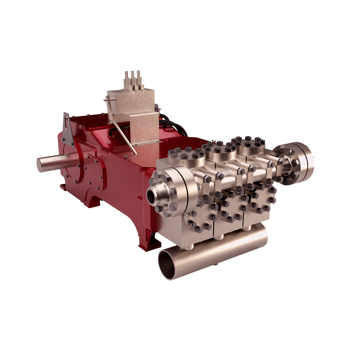
A triplex mud (or slush) pump has three horizontal plungers (cylinders) driven off of one crankshaft. Triplex mud pumps are often used for oil drilling.
Oil and Gas drilling process - Pupm output for Triplex and Duplex pumpsTriplex Pump Formula 1 PO, bbl/stk = 0.000243 x ( in) E.xample: Determine the pump output, bbl/stk, at 100% efficiency for a 7" by 12". triplex pump: PO @ 100%,= 0.000243 x 7 x12 PO @ 100% = 0.142884bbl/stk Adjust the pump output for 95% efficiency: Decimal equivalent = 95 + 100 = 0.95 PO @ 95% = 0.142884bbl/stk x 0.95 PO @ 95% = 0.13574bbl/stk Formula 2 PO, gpm = [3(D x 0.7854)S]0.00411 x SPM where D = liner diameter, in. S = stroke length, in. SPM = strokes per minute Determine the pump output, gpm, for a 7" by 12". triplex pump at 80 strokes per minute: PO, gpm = [3(7 x 0.7854) 1210.00411 x 80 PO, gpm = 1385.4456 x 0.00411 x 80 PO = 455.5 gpm
Example:Duplex Pump Formula 1 0.000324 x (liner diameter, in) x ( stroke lengh, in) = ________ bbl/stk -0.000162 x (rod diameter, in) x ( stroke lengh, in) = ________ bbl/stk Pump out put @ 100% eff = ________bbl/stk Example: Determine the output, bbl/stk, of a 5 1/2" by 14" duplex pump at 100% efficiency. Rod diameter = 2.0": 0.000324 x 5.5 x 14 = 0.137214bbl/stk -0.000162 x 2.0 x 14 = 0.009072bbl/stk Pump output @ 100% eff. = 0.128142bbl/stk Adjust pump output for 85% efficiency: Decimal equivalent = 85 100 = 0.85 PO@85%)= 0.128142bbl/stk x 0.85 PO@ 85% = 0.10892bbl/stk Formula 2
PO. bbl/stk = 0.000162 x S[2(D) - d] where S = stroke length, in. D = liner diameter, in. d = rod diameter, in. Example: Determine the output, bbl/stk, of a 5 1/2". by 14". duplex pump @ 100% efficiency. Rod diameter = 2.0in.: PO@100%=0.000162 x 14 x [ 2 (5.5) - 2 ] PO @ 100%)= 0.000162 x 14 x 56.5 PO@ 100%)= 0.128142bbl/stk Adjust pump output for 85% efficiency: PO@85%,= 0.128142bb/stkx 0.85 PO@8.5%= 0.10892bbl/stk Metric calculation Pump output, liter/min = pump output. liter/stk x pump speed, spm. S.I. units calculation Pump output, m/min = pump output, liter/stk x pump speed, spm. Mud Pumps Mud pumps drive the mud around the drilling system. Depending on liner size availability they can be set up to provide high pressure and low flow rate, or low pressure and high flow rate. Analysis of the application and running the Drill Bits hydraulics program will indicate which liners to recommend. Finding the specification of the mud pumps allows flow rate to be calculated from pump stroke rate, SPM. Information requiredo Pump manufacturer o Number of pumps o Liner size and gallons per revolution Weight As a drill bit cutting structure wears more weight will be required to achieve the same RoP in a homogenous formation. PDC wear flats, worn inserts and worn milled tooth teeth will make the bit drill less efficiently. Increase weight in increments of 2,000lbs approx. In general, weight should be applied before excessive rotary speed so that the cutting structure maintains a significant depth of cut to stabilise the bit and prevent whirl. If downhole weight measurements are available they can be used in combination with surface measurements to gain a more accurate representation of what is happening in the well bore.

Pump OutputDuplex Pump OutputLitres/Stroke @ 90% Efficiency (2” Rod Diameter)Liner Diamerter (mm)StrokeLength(mm)101 108 114 121 127 133 140 146 152 159 165 170 178 184 190 197 203 209 216203 5.40 6.19 6.99 7.78 8.73 6.69 10.6 11.5 12.7 13.8 15 16.2 17.4 18.9254 6.67 7.62 8.58 6.69 10.8 12.0 13.3 14.6 15.9 17.3 18.7 20.0 21.9 23.6305 7.78 9.90 10.10 11.40 12.9 14.3 15.9 17.3 19.1 20.7 22.6 24.3 26.2 28.3 30.4356 14.6 16.4 18.0 19.9 21.8 23.8 25.9 28.0 30.2 32.4 35.0 37.4 39.9381 15.6 17.3 19.2 21.1 23.2 25.3 27.5 29.7 32.3 34.7 37.4 39.9 42.8406 16.7 18.6 20.5 22.6 24.8 27.0 29.4 32.3 34.5 37.0 39.7 42.8 45.6 48.6457 18.4 20.7 22.7 25.3 27.8 30.2 32.7 35.6 38.5 41.3 44.5 47.7 51.1 54.4508 20.3 22.7 25.1 28.0 30.5 33.4 36.4 39.4 46.2 45.9 49.4 53.1 56.8 60.4559 49.8 53.5 57.3 61.1 65.1 69.2 73.5610 71.1 75.6 80.2Note: For pump output in m 3 /stroke, move the decimal point 3 places to the left.Duplex Mud PumpsThe pistons on a duplex mud pump work in both directions, so that the rear cylinder has thepump rod moving through its swept volume and occupying some volume. The difference incalculations for a duplex vs. a triplex pump is that the displacement volume of this pump rodmust be subtracted from the volume in one of the cylinders, plus the difference in number ofpumping cylinders; 4 for a duplex and 3 for a triplex. Duplex pumps generally have longerstrokes (in the 10 to 18 in. range) and operate at lower rate; in the 40 to 80 stroke/minrange.The general equation to calculate output of a duplex pump is:Pump output (litres/stroke) = ,Where:ID = ID of the linerOD = OD of the rodL = Length of the pump strokeEff = Pump efficiency (decimal)1800, 505 – 3 rd Street SW Calgary, Alberta, Canada T2P 3E6 Telephone: 403.547.2906 Fax: 403.547.3129Email: info@hitechfluid.com Web: www.hitechfluid.com

Pumps tend to be one of the biggest energy consumers in industrial operations. Pump motors, specifically, require a lot of energy. For instance, a 2500 HP triplex pump used for frac jobs can consume almost 2000 kW of power, meaning a full day of fracking can cost several thousand dollars in energy costs alone!
So, naturally, operators should want to maximize energy efficiency to get the most for their money. Even a 1% improvement in efficiency can decrease annual pumping costs by tens of thousands of dollars. The payoff is worth the effort. And if you want to remotely control your pumps, you want to keep efficiency in mind.
In this post, we’ll point you in the right direction and discuss all things related to pump efficiency. We’ll conclude with several tips for how you can maintain pumping efficiency and keep your energy costs down as much as possible.
In simple terms, pump efficiency refers to the ratio of power out to power in. It’s the mechanical power input at the pump shaft, measured in horsepower (HP), compared to the hydraulic power of the liquid output, also measured in HP. For instance, if a pump requires 1000 HP to operate and produces 800 HP of hydraulic power, it would have an efficiency of 80%.
Remember: pumps have to be driven by something, i.e., an electric or diesel motor. True pump system efficiency needs to factor in the efficiency of both the motor AND the pump.
Consequently, we need to think about how electrical power (when using electric motors) or heat power (when using combustion engines) converts into liquid power to really understand pump efficiency.
Good pump efficiency depends, of course, on pump type and size. High-quality pumps that are well-maintained can achieve efficiencies of 90% or higher, while smaller pumps tend to be less efficient. In general, if you take good care of your pumps, you should be able to achieve 70-90% pump efficiency.
Now that we have a better understanding of the pump efficiency metric, let’s talk about how to calculate it. The mechanical power of the pump, or the input power, is a property of the pump itself and will be documented during the pump setup. The output power, or hydraulic power, is calculated as the liquid flow rate multiplied by the "total head" of the system.
IMPORTANT: to calculate true head, you also need to factor in the work the pump does to move fluid from the source. For example, if the source water is below the pump, you need to account for the extra work the pump puts in to draw source water upwards.
*Note - this calculation assumes the pump inlet is not pressurized and that friction losses are minimal. If the pump experiences a non-zero suction pressure, or if there is significant friction caused by the distance or material of the pipe, these should be factored in as well.
You"ll notice that the elevation head is minimal compared to the discharge pressure, and has minimal effect on the efficiency of the pump. As the elevation change increases or the discharge pressure decreases, however, elevation change will have a greater impact on total head.
Obviously, that’s a fair amount of math to get at the pump efficiency, considering all of the units conversions that need to be done. To avoid doing these calculations manually, feel free to use our simple pump efficiency calculator.
Our calculations use static variables (pump-rated horsepower and water source elevation) and dynamic variables (discharge flow and pressure). To determine pump efficiency, we need to measure the static variables only once, unless they change.
If you want to measure the true efficiency of your pump, taking energy consumption into account, you could add an electrical meter. Your meter should consist of a current transducer and voltage monitor (if using DC) for electrical motors or a fuel gauge for combustion. This would give you a true understanding of how pump efficiency affects energy consumption, and ultimately your bank account.
Up until this point, we’ve covered the ins and outs of how to determine pump efficiency. We’re now ready for the exciting stuff - how to improve pump efficiency!
One of the easiest ways to improve pump efficiency is to actually monitor pumps for signs of efficiency loss! If you monitor flow rate and discharge (output power) along with motor current or fuel consumption, you’ll notice efficiency losses as soon as they occur. Simply having pump efficiency information on hand empowers you to take action.
Another way to increase efficiency is to keep pumps well-maintained. Efficiency losses mostly come from mechanical defects in pumps, e.g., friction, leakages, and component failures. You can mitigate these issues through regular maintenance that keeps parts in working order and reveals impending failures. Of course, if you are continuously monitoring your pumps for efficiency drops, you’ll know exactly when maintenance is due.
You can also improve pump efficiency by keeping pumps lubricated at all times. Lubrication is the enemy of friction, which is the enemy of efficiency (“the enemy of my enemy is my friend…”).
A fourth way to enhance pump efficiency is to ensure your pumps and piping are sized properly for your infrastructure. Although we’re bringing this up last, it’s really the first step in any pumping operation. If your pumps and piping don’t match, no amount of lubricant or maintenance will help.
In this post, we’ve given you the full rundown when it comes to calculating and improving pump efficiency. You can now calculate, measure, and improve pump efficiency, potentially saving your business thousands of dollars annually on energy costs.
For those just getting started with pump optimization, we offer purpose-built, prepackaged solutions that will have you monitoring pump efficiency in minutes, even in hazardous environments.

This approach works well but relying on a printed reference is not without the risk since the wrong value can still be selected from the fine print of a reference table, or the reference document can be damaged or lost (e.g., dropped in the mud pit) altogether.
So, let’s address the alternative approach of using simple mathematical formulas to determine the same information. Although the reliance on a single sheet of paper to obtain the needed value is avoided with this approach, the potential for human error or miscalculation remains, meaning regardless of the approach, great care in determining such values is prudent.
As we consider the various calculations that enable us to determine the values of length, weight, pressure, volume, flow velocity, etc., we should remain mindful of the units of measure we’re dealing with. The groundwater industry uses units of measure that are somewhat intermingled with other units from associated disciplines such as engineering, surface water hydrology, and the oil and gas drilling industry.
We want to know the volume of material (filter pack sand, cement grout, etc.) that is to be placed in the annulus to assure the annular void has been properly and completely filled (Figure 1). The conceptual diagram showing the variables used for calculating an annular void is shown in Figure 2, and the formula for the annular volume calculation is:
In this calculation, the “d” value is the diameter of the casing or pipe diameter, and the “D” value is the borehole diameter (Figure 2). The sump area below the base of the casing has only one diameter in the open borehole, so the “d” value is omitted, and the formula just becomes:
If excessive hydraulic pressures are exerted on a well casing, it will collapse. We generally know the collapse strength of the well casing from the casing supplier or from standard references such as the charts in American Water Works Association Standard A100. The hydraulic pressures applied to the outside of the well casing depend on the density of the liquid and the depth of submergence (Figure 1). Applying the fluid density (measured in the field) and depth (Figure 2), the formula for hydraulic pressure head calculation is:
The hydraulic head formula is applicable to the hydraulic pressure head for any liquid, but we most commonly use this calculation during cement seal installation, since cement grout is generally the heaviest liquid being introduced to the annulus during well construction.
The intermediate casing can be sealed using the pressure grouting technique (Figure 3) to pump cement slurry down through the drill pipe and out to the annulus through a float shoe (a drillable check valve connected to the base of the casing). The inside of the intermediate casing is kept full of water during the cement placement to equilibrate hydraulic pressures inside and outside the casing. After the intermediate casing is sealed with the pressure grouted cement, the float shoe can be drilled out and the borehole advanced for installation of the screen and filter pack in the lower part of the well.
Floating of a casing string introduces serious logistical and safety hazards and creates significant disruption to the integrity of the annular seal. The potential for floating of the intermediate casing can be easily mitigated by securing it at the land surface, but the driller needs to know that this is required before the cementing operations begin. Thus, a buoyancy calculation is a good idea prior to pressure grouting operations as illustrated in Figure 3.
The buoyancy calculation is more of a conceptual comparison than a pure mathematical formula. This analysis involves some visualization be made on the part of the groundwater professional.
If you apply the weight calculations for a 400-foot-long steel casing with a 16-inch diameter and a 5/16-inch wall thickness, which is filled with water, you’ll see that the downward force in this example is only 52,982 pounds. Thus, the casing in this example will float. The lesson from this counterintuitive scenario is that a casing can actually float. (I’ve seen it happen, and trust me, you don’t want to).
There are several calculations that are commonly applied by drilling fluid engineers (mud engineers) to determine the time period required for the fluid to move from one location in the borehole to another. Some of the more common equations are described below.
The uphole velocity calculation provides a determination of the speed at which the drilling mud will flow as it moves up the borehole. For direct air rotary or reverse circulation drilling methods, the uphole velocity is high, so this calculation is generally applicable only for the direct mud-rotary drilling method. The formula for uphole velocity is:
Notice the uphole velocity formula is similar to the annular volume formula in that both those calculations use the factor (D2 – d2) to address the cross-sectional area of the annulus. However, the constants in these two formulas are different (0.005454 versus 24.51), which can be confusing. Keep in mind, however, that the constants primarily just provide unit conversions.
Thebottoms-up time calculation enables us to determine the time period for the drilling fluid (and the cuttings it is carrying) to travel from the drill bit up to the land surface. This is illustrated in Figure 6(A).
We can calculate the bottoms-up time by using the uphole velocity formula with the borehole depth and drilling mud flow rate plugged in, but that flow rate is being generated by the mud pump, and positive displacement mud pumps (duplex or triplex) are almost never equipped with a flow meter. To determine the flow coming from the mud pump, we can use the formulas:
Remember the strokes are counted in both the forward and backward directions on a duplex pump, but only in the forward direction on a triplex pump. Drillers often have reference charts that provide oilfield barrels per stroke (bbl/stroke), which can be converted to gpm by timing the strokes per minute and converting barrels to gallons (1 barrel = 42 gallons).
The round-trip time enables us to see the result of drilling fluid additives, as indicated by the return flow of fluids at the land surface, as is illustrated in Figure 6(B). The round-trip time calculation is the same as bottoms-up time, but with the travel time of fluid to displace the drill pipe added in.
A specified volume of drilling fluids (called a pill) can be circulated to a particular depth interval within the borehole (called spotting), so that the additives in the pill of drilling mud can address the borehole problem at a particular depth of the borehole. This is shown in Figure 6(C).
The calculation for time required to spot a pill of drillingfluid involves determining the pumping time (at the calculated flow rate) required to displace the fluid so that the drilling mud additives are located adjacent to the problematic interval. This approach is used by mud engineers to address problems such as lost circulation or stuck drill pipe.
The formulas and calculations provided in this column and elsewhere provide important tools for us to quantify the variables we need for water well design and construction. However, it is important to remember that “doing the math” is not a replacement for applying professional knowledge and consideration to determine whether the mathematical result makes common sense.


 8613371530291