
vintage two man hand mud pump brands

In 1848 Seabury S. Gould purchased an interests in Downs, Mynderse & Co. and the firm became Downs & Co. Wooden pumps were produced in an old cotton factory building. In 1869, the name of the company was changed from Downs & Company to Goulds Manufacturing Company.
Seabury S. Gould, a man of unusual vision, was the founder of Goulds Manufacturing Company. He keenly watched as the first pump casting emerged from its mold of sand. An iron pump, he believed, would overcome all the disadvantages of a wooden pump. It would be strong and efficient and provide fresh flowing water for the pioneers. He ran the company until after the Civil War.
Because Goulds Manufacturing Company had a foundry, they produced all kinds of cast products such as corn shellers, bells, sad irons, sinks, tools, and a line of fire engines.
This Goulds bell, still rings loud and clear 169 years after it was manufactured. The bell sold for $8 and was used in farms, plantations, school houses and factories. It was dedicated at the opening of the new Goulds corporate headquarters on May 13, 1979.

Editor"s Note: This is the second of five parts of our feature, The History of Pumps. This timeline was developed through research, credible sources and the knowledge of friends in the industry, The history of pumps is long and illustrious. This account represents highlights of some of the major historical and technological developments. We welcome your contributions.
200 BC Greek inventor and mathematician Ctesibius invents the water organ, an air pump with valves on the bottom, a tank of water in between them and a row of pipes on top. This is the principal design that is now known as the reciprocating pump.
200 BC Archimedean screw pump is designed by Archimedes is considered one of the greatest inventions of all time and is still in use today for pumping liquids and granulated solids in both the industrialized world and in the third world—where it is a preferred way to irrigate agricultural fields without electrical pumps.
1475 According to Reti, the Brazilian soldier and historian of science, the first machine that could be characterized as a centrifugal pump was a mud lifting machine that appeared in a treatise by the Italian Renaissance engineer Francesco di Giorgio Martini.
1588 Sliding vane water pump technology is described by Italian engineer Agostino Ramelli in his book “The Diverse and Artifactitious Machines of Captain Agostino Ramelli,” which also included other pump and engine designs.
1636 Pappenheim, a German engineer, invents the double deep-toothed rotary gear pump, which is still used to lubricate engines. This gear pump made it possible to dispense with the reciprocating slide valves used by Ramelli. Pappenheim drove his machine by an overshot water wheel set in motion by a stream and was used to feed water fountains. The emperor Ferdinand II granted him a “privilege” - the equivalent of a patent - in respect of this invention.
1675 Sir Samuel Moreland—an English academic, diplomat, spy, inventor and mathematician—patents the packed plunger pump, capable of raising great quantities of water with far less proportion of strength than a chain or other pump. The piston had a leather seal. Moreland"s pump may have been the first use of a piston rod and stuffing box (packed in a cylinder) to displace water.
1790 Briton Thomas Simpson harnesses steam power to pumping engines for municipal water applications and founds the London company Simpson and Thompson Co. (predecessor to Worthington Simpson).
1845 Henry R. Worthington invents the first direct-acting steam pumping engine. Worthington Pump designed its first products to power canal boats and U.S. naval vessels. Worthington later pioneered pump designs for boiler feed, oil pipeline and hydro-electric applications.
1848 In Seneca Falls, N.Y., Seabury S. Gould purchases the interests of Edward Mynderse and H.C. Silsby in Downs, Mynderse & Co., forming Downs & Co., later known as Goulds Manufacturing Company.
1851 John Gwynne files his first centrifugal pump patent. His early pumps were used primarily for land drainage, and many can still be seen today in pump house museums. They were usually powered by Gwynnes" steam engines. By the end of the 19th century, Gwynne was producing pumps of all sizes to cover all industrial applications, from small electric pumps to those rated at 1,000 tons per minute. His company had also begun to produce scientific pumps, e.g., porcelain pumps for chemical works. In the 1930s they were producing almost 1,000 different models.
1860 Adam Cameron founds the Cameron Steam Pump Works, and becomes another pioneer in reciprocating steam pump engines. Like Worthington, Cameron"s first products were used to power merchant marine and U.S. naval vessels. Cameron pumps were later applied in water resources, oil pipeline and refining and boiler feed.
1871 Johannes Klein receives a patent on his “boiler feed apparatus.” With Friedrich Schanzlin and Jakob Becker, he founds the company “Frankenthaler Maschinen- & Armatur-Fabrik Klein, Schanzlin & Becker” (now known as KSB) to manufacture boiler feed equipment and valves.
1886 Jens Nielsen, founder of Viking Pump Company, invents the internal gear pumping principal while designing a pump to remove excess water that was seeping into his limestone quarry from a nearby creek.
1886 United Centrifugal Pumps is incorporated. It becomes the world"s foremost supplier of high-pressure crude oil and refined product pipeline pumps.
1899 Robert Blackmer invents rotary vane pump technology, a pump design that was an important departure from the old gear principle and predecessor to today"s sliding vane pumps.
1902 Aldrich Pump Company begins manufacturing the world"s first line of reciprocating positive displacement pumps for steel mills and mine dewatering.
1908 Hayward Tyler creates its first electric motor for use under water and develops the wet stator motor for use as a boiler circulation glandless motor-pump.
1911 Jens Nielsen builds the first internal gear pump, founding the Viking Pump Company. The Viking Rotary “Gear-Within-A-Gear” pump (the first of its kind) is placed on the market.
1912 Durion, a universally corrosion-resistant material, is invented by the Duriron Castings Company (later known as Durco Pump) and is applied to process equipment.
1915 Albert Baldwin Wood invents the Wood trash pump. Wood spearheads the reclamation from swamp and the efforts to develop much of the land now occupied by the city of New Orleans. Some of Wood"s pumps have been in continuous use for more than 80 years without need of repairs. New ones continue to be built from his designs.
1916 While Armais Sergeevich Arutunoff first invented submersible pumps in Russia in 1916, their use in the United States did not begin until the 1950s. Arutunoff first designed his pump for use in ships, water wells and mines. He altered the design to work in oil wells. Thanks to further refinements to Arutunoff"s design, there are more types of submersible pumps, allowing use in other applications such as pumping drinking water, creating fountains and pumping wastewater.
1921 Harry LaBour founds LaBour Pump Company. A pioneer in the development of pumps for the chemical industry, LaBour developed corrosion-resistant alloys to incorporate into his pumps. Until his time, sulfuric acid was always pumped with lead pumps, the only known material that could handle certain concentrations of the acid.
1921 Jeumont-Schneider begins manufacturing water and slurry pumps in Jeumont, France. It later develops solids-handling pumps and segmental ring section multistage pumps.
1924 Durco Pump introduces the world"s first pump specifically designed for chemical processing. It would go on to establish undisputed global leadership in ANSI pump design.
1926 O.H. Dorer receives a patent for the first inducer, which reduces the required NPSH. Inducers did not become incorporated into standard pump lines until the 1960s.
1929 Pleuger incorporates in Berlin, Germany. Its first offerings are submersible motor pumps for dewatering in the construction of underground railways and subways. Pleuger pioneers the first successful application of submersible motor pumps in offshore service.
1929 Stork Pompen produces the first concrete volute pump for drainage, integrating the pump housing in the civil construction of the pumping station.
1930 While inventing a compressor for jet engines, aviation pioneer René Moineau discovers that this principle could also work as a pumping system.The University of Paris awarded Moineau a doctorate of science for his thesis on “the new capsulism.” His pioneering dissertation laid the groundwork for the progressing cavity pump.
1933 The original version of the Bush Pump is designed as a closed-top cylinder pump. In 1960 the design was modernized. The base of the well was from then on bolted to the well casing and got its current name, The Zimbabwe Bush Pump, the National Standard for hand pumps in Zimbabwe. After Zimbabwe"s independence in 1980, the government creates its own modernized version of the pump, B-type Zimbabwe Bush Pump. The pump is today regarded as a national treasure. In 1997, it was pictured on a postal stamp.
1933 J.C. Gorman and Herb Rupp introduce a pump with a “non-clogging” feature. It outperforms any other self-priming centrifugal pump previously invented. The company Gorman-Rupp is established.
1936 Robert Sheen invents the metering pump. The core of his invention was a method of controlled volume that was inherent to the pump. The first pumps were assembled in the basement of his father, Milton Roy Sheen"s, home, where the initial patterns for castings were made.
1937-1939 Smith Precision Products Company (Smith Pumps) designs three pumps, two of which (models 300 and 200) were specifically designed for LP-gas transfer.
1939 Dorr-Oliver Pump Company develops the Oliver Diaphragm Slurry pump for slurry transfer. Originally designed for mining slurry transfer with their associated acids, it developed into a Primary Sludge Underflow Pump for the wastewater industry starting in the 1970s after the Clean Water Act.
1940 Reuben Smith, of Smith Precision Products Company (Smith Pumps), receives the first approval for an LP-gas pump from the California Industrial Accident Commission. This was for the model 4X pump and the approval was a "suitable for use" certificate.
1942 The Gorman-Rupp team creates the first commercially available solids-handling trash pump to respond to the contractor"s need for a pump to withstand the considerable rigors of pumping out trash-laden septic tanks, cesspools and outhouses.
1944 During World War II, Goulds extra-quiet trim pumps are installed in every U.S. Navy submarine. That year, 157 Goulds men went to war and 157 women took their places on the Goulds manufacturing floor. Goulds earned the prestigious Army-Navy “E” Award that year for outstanding production of war materials.
1947 Flygt"s Sixten Englesson, a master of engineering, develops a prototype for the first submersible drainage pump, which is later known as the “parrot cage,” or B-pump, used in mining for construction.
1948 Smith Precision Products Company receives the patent for the first mechanical seal supplied for liquefied gas transfer pumps. It was first put into production in 1947.
1950 Vanton develops the Flex-i-liner sealless self-priming rotary pump which handles corrosive, abrasive and viscous fluids as well as those that must be transferred free of product contamination.
1954 Smith Precision Products Company (Smith Pumps) begins working with the Underwriters Laboratories to develop their first Standard for liquefied gas pumps, UL-51, which is still in use today.
In 1955, Jim Wilden invented air-operated double-diaphragm pump technology. It had the right air valve and diaphragms needed and was tough and versatile enough to meet the stringent demands of the mining and heavy-construction industries. During the 1980s, Wilden introduced plastic AODD pumps that have the ability to stand up to the harsh operating conditions and corrosive media transferred throughout the global chemical market. Photo courtest of Wilden.
1960s New lines of industrial pumps are developed by Goulds Pumps, including large double suction pumps, higher pressure pumps and non-metallic pumps. In home water systems, the jet water system is improved and a complete line of submersible pumps is completed.
1965 Warren Rupp"s heavy-duty, diverse AODD pump is introduced to the industrial market to address the vigorous demands of the steel mills and other industrial market applications.
Below: Marvin and Kathryn Summerfield founded Cascade Pump Company in 1948. They are pictured here at an industry tradeshow in the early 1950s. Photo courtesy of Cascade Pump Company.
1968 The ownership of Stenberg-Flygt AB is transferred to the American multinational enterprise ITT (International Telephone & Telegraph Corporation). Prior to this transfer, Stenberg-Flygt AB, AB Flygts Pumpar and Flygt International AB are consolidated as a single company.
1980s Gorman-Rupp unveils the nutating pump, a special purpose small pump used in health care applications; additional energy-efficient, self-priming centrifugal pumps; a series of lightweight portable pumps and high-pressure pumps with the first digital-control panels.
1985 Sims manufactures the first structural composite pump, all Simsite Vertical Pit Pump. Sims later won the Innovative Product Award for these products in 1990.
In 1933, J.C. Gorman and Herb Rupp introduced a pump which had a "non-clogging" feature. Their competitors claimed the pump would not work in a savage public awareness campaign to discredit the new design, which resulted in about $100,00 worth of "free advertising." At least one customer was willing to try it. National Ice Company purchased the first pump, and the company Gorman-Rupp was established. Photo courtesy of Gorman-Rupp Company.
1994 Two new major products are introduced by Goulds Pumps, the Industrial Model 3298 Magnetic Drive Pump and the Water Technologies Model GS “Global Submersible.”
1994 Sims receives the honor of approval from the United States Navy for composite centrifugal pump intervals. Simsite was tested and qualified for centrifugal pump replacement parts and was the first composite to be certified.
1994 Baha Abulnaga invents the slurry and froth pump with a split vane impeller. The split impeller helps to reduce recirculation in slurry pumps by dividing the space between the main vanes without reducing the passageway at the narrowest point, which is the eye of the impeller. In froth pumps, it helps to break up air bubbles that form and tend to block the flow.
1995 Sims manufactures the largest structural composite pumps in the world - two Simsite vertical turbine pumps for Potomac Electric Power Company. They are 40 feet long and 3 feet in diameter.
2006 Sims manufactures the largest structural composite centrifugal impeller in the world. This huge impeller was installed in a cooling tower pump for Puerto Rican Electrical Power Company. It is 50 inches in diameter and consumes 2,000 horsepower.

Garden Antiques└ Architectural & Garden Antiques└ AntiquesAll CategoriesAntiquesArtBabyBooks & MagazinesBusiness & IndustrialCameras & PhotoCell Phones & AccessoriesClothing, Shoes & AccessoriesCoins & Paper MoneyCollectiblesComputers/Tablets & NetworkingConsumer ElectronicsCraftsDolls & BearsMovies & TVEntertainment MemorabiliaGift Cards & CouponsHealth & BeautyHome & GardenJewelry & WatchesMusicMusical Instruments & GearPet SuppliesPottery & GlassReal EstateSpecialty ServicesSporting GoodsSports Mem, Cards & Fan ShopStampsTickets & ExperiencesToys & HobbiesTravelVideo Games & ConsolesEverything Else
RM2MF3D54–Kikuube, Uganda. 24th Jan, 2023. A worker operates the Mud Pump Unit at the Kingfisher Oil Field in Kikuube, Uganda, on Jan. 24, 2023. Uganda on Tuesday started the drilling of oil for commercial production in the Western Region district of Kikuube on the shores of Lake Albert. Ugandan President Yoweri Museveni launched the drilling process at the Kingfisher Oil Field, operated by the Chinese oil giant China National Offshore Oil Corporation (CNOOC). Credit: Hajarah Nalwadda/Xinhua/Alamy Live News

Mud Pumps come in both electric and gas / diesel engine drive along with air motors. Most of these pumps for mud, trash and sludge or other high solids content liquid dewatering, honey wagon and pumper trucks. Slurry and mud pumps are often diaphragm type pumps but also include centrifugal trash and submersible non-clog styles.
WARNING: Do not use in explosive atmosphere or for pumping volatile flammable liquids. Do not throttle or restrict the discharge. Recommend short lengths of discharge hose since a diaphragm mud pump is a positive displacement type and they are not built with relief valves.

This ¼-horsepower sump pump weighs 6.8 pounds and moves up to 1,800 gallons per hour (gph) to keep your basement or low-lying area safe from floodwater. Built with thermoplastic, this sump pump is a durable flood-prevention device that includes a removable suction screen.
Customers with varying needs found this sump pump to be useful, stating that it operated efficiently and quietly. They added that the pump’s filter did a great job in preventing the unit from getting clogged due to dirt, debris, or algae build-up. Customers who were disappointed in this product wished that it would’ve lasted longer, citing reliability and longevity issues.
This submersible sump pump is built with cast-iron motor components that withstand a variety of conditions and keep your home protected from rising water. It includes a float-activated switch that automatically powers the pump when it detects rising water levels.
Although customer feedback was mixed, over 80% of reviewers gave this sump pump a five-star rating at the time of this review. Happy customers mentioned the pump’s simple installation and affordable price point in their positive reviews. Unhappy customers said that while the pump was heavy-duty, it shorted out after a few years, expecting greater longevity out of the product. Additionally, one user had issues with the flow valve leaking.
This sump pump has a 1⁄3-horsepower motor activated by a vertical float switch to keep your basement dry. It’s designed with quality cast iron and stainless steel, minimizing the risk of air locks and clogs. The sump pump works in sump basins that are 11 inches or larger.
Positively, customers who give this sump pump a four- or five-star rating reported that the unit consistently moved water without any issues, meeting or exceeding their expectations. In some reviews, they also mentioned that the manufacturer’s Halo mobile app was convenient for remotely monitoring the pump’s status. Negatively, there were complaints about the pump’s float switch working intermittently rather than consistently.
This unit is built for large 16-inch sump basins and has a built-in backup battery that pumps up to 10,000 gallons of water on a single charge. It has a ½-horsepower motor protected by a durable cast-iron and epoxy-coated steel frame, pumping 5,100 gallons of water per hour.
Positive aspects of this sump pump that users highlighted included its compact size, fast installation, quiet operation, and overall power. On the other hand, several reviewers reported that the manufacturer was slow to respond to their inquiries, or didn’t respond at all, despite multiple attempts. One user also complained about the plastic threads in the discharge outlet, stating that it was difficult to screw in adapters.
This model is equipped with a piggyback plug that lets homeowners automatically or manually turn on the pump to discharge up to 2,760 gallons of water per hour. It includes a ⅓-horsepower motor contained inside a heavy-duty cast-iron frame to secure the pump inside the pit.
Satisfied users who gave this pump positive reviews said that it was an effective pump that performed just as strongly after two years of use as it did on the first day of use. They also appreciated the pump’s effortless installation. Conversely, there were some reports of the sump pump’s cast iron materials prematurely rusting, rendering the unit useless for a handful of customers. Additionally, some users said that the float switch was too short, which lead to excess standing water.
With its thermoplastic materials and 1/4-horsepower motor, this sump pump will make sure that your property remains undamaged due to excess water intrusion. Its built-in bottom suction filter removes water down to a 1/4-inch of the surface to prevent dirt clogging.
Given the pump’s entry-level price point, several customers were impressed with how reliable and powerful it was. They mentioned that the pump was effective for draining pools, adding that the 10-foot power cord offered some flexibility with the positioning of the pump. Alternatively, there were some complaints about the unit’s inability to pump viscous, muddy water, and others wished that the unit pumped water faster.
Submersible sump pumps are completely submerged in the pit, or sump basin, that’s located below your basement’s floor. Once the pit fills with a certain amount of water, a sensor is triggered, which turns on the sump pump to pump the water out. This type of sump pump is typically quieter than other types of sump pumps because its motor is inside the pump, but it’s more expensive than other pumps.
Pedestal sump pumps sit in a basin that’s level with your basement floor and remove water through a pipe that leads to a drainage area in your yard. They’re more affordable than submersible sump pumps, but their motor is attached to the outside of the device, making them noisier.
Unlike submersible and pedestal models that run solely on electricity through a power cord, battery backup sump pumps have a battery-powered backup pump that kicks on when the main unit can’t run due to a power outage. The battery on the backup pump can typically last for a few hours on a single charge. While this is enough for short surges, the battery will eventually die if it’s pumping a lot of water during an hours-long outage.
Combination sump pumps include the power cord of pedestal and submersible models and the backup battery of battery models, allowing them to work in all situations. They usually sit in a below-the-floor basin like submersible sump pumps, but they’re larger, which means you can’t use the basin you dug for your old submersible sump pump for your new combination sump pump.
Before purchasing and installing a sump pump, it’s important to understand how each model’s design and specifications impact its performance. Here are a few factors to consider when buying a sump pump.
Most sump pumps are powered by electricity, but some models include a battery backup that powers the device in the event of a blackout. For example, some pumps include a battery that can pump thousands of gallons on a single charge. Models that don’t have a battery backup can pump thousands of gallons of water per hour as long as electricity is available.
The horsepower (HP) of a sump pump’s motor refers to its overall power, with a higher HP motor being able to pump more water per hour than a lower HP motor. Many sump pumps contain ½-HP or ⅓-HP engines, though some models contain more powerful ¾-HP engines. While higher HP motors can pump more water per hour, they’re typically more expensive.
Most sump pumps use either a digital or manual switch to start their motors. Manual models contain floats that rise with the flood water, turning on the pumps when the water reaches a certain level. When the floats dip below the set level, the pump stops.
Other models feature digital on-and-off sensors. When the water rises to meet the on sensor, the pump starts working. Once the water lowers and reaches the off sensor, the pump turns off. The benefit of digital switches is that they continue pumping water until they reach the off sensor, even if the water level dips below the on sensor.
Sump pumps are usually made of plastic or some sort of metal, such as aluminum, stainless, steel, or cast iron. Plastic sump pumps are more affordable, but they’re not as durable as metal sump pumps.
A sump pump is typically placed in a basement to prevent damage brought on by significant flooding. It detects rising water levels and then pumps that water out of your basement and directs it away from your home.
Sump pumps can develop an odor if they haven’t been used in a while. Infrequent use causes the water in the pump’s basin to fully dry, releasing smelly gases into the air. Mold and bacteria growth inside the pump and the basin can also cause a smell.
You can eliminate these odors by creating a solution with a ratio of 1 cup of bleach to every 1 gallon of water. Pour this solution into the basin until the pump is activated. To prevent an odor from developing in the future, wash your sump pump regularly and keep the basin full of enough fresh water to cover the drain lines.

Mechanical pumps serve in a wide range of applications such as pumping water from wells, aquarium filtering, pond filtering and aeration, in the car industry for water-cooling and fuel injection, in the energy industry for pumping oil and natural gas or for operating cooling towers and other components of heating, ventilation and air conditioning systems. In the medical industry, pumps are used for biochemical processes in developing and manufacturing medicine, and as artificial replacements for body parts, in particular the artificial heart and penile prosthesis.
When a pump contains two or more pump mechanisms with fluid being directed to flow through them in series, it is called a multi-stage pump. Terms such as two-stage or double-stage may be used to specifically describe the number of stages. A pump that does not fit this description is simply a single-stage pump in contrast.
In biology, many different types of chemical and biomechanical pumps have evolved; biomimicry is sometimes used in developing new types of mechanical pumps.
Pumps can be classified by their method of displacement into positive-displacement pumps, impulse pumps, velocity pumps, gravity pumps, steam pumps and valveless pumps. There are three basic types of pumps: positive-displacement, centrifugal and axial-flow pumps. In centrifugal pumps the direction of flow of the fluid changes by ninety degrees as it flows over an impeller, while in axial flow pumps the direction of flow is unchanged.
Some positive-displacement pumps use an expanding cavity on the suction side and a decreasing cavity on the discharge side. Liquid flows into the pump as the cavity on the suction side expands and the liquid flows out of the discharge as the cavity collapses. The volume is constant through each cycle of operation.
Positive-displacement pumps, unlike centrifugal, can theoretically produce the same flow at a given speed (rpm) no matter what the discharge pressure. Thus, positive-displacement pumps are constant flow machines. However, a slight increase in internal leakage as the pressure increases prevents a truly constant flow rate.
A positive-displacement pump must not operate against a closed valve on the discharge side of the pump, because it has no shutoff head like centrifugal pumps. A positive-displacement pump operating against a closed discharge valve continues to produce flow and the pressure in the discharge line increases until the line bursts, the pump is severely damaged, or both.
A relief or safety valve on the discharge side of the positive-displacement pump is therefore necessary. The relief valve can be internal or external. The pump manufacturer normally has the option to supply internal relief or safety valves. The internal valve is usually used only as a safety precaution. An external relief valve in the discharge line, with a return line back to the suction line or supply tank provides increased safety.
Rotary-type positive displacement: internal or external gear pump, screw pump, lobe pump, shuttle block, flexible vane or sliding vane, circumferential piston, flexible impeller, helical twisted roots (e.g. the Wendelkolben pump) or liquid-ring pumps
Drawbacks: The nature of the pump requires very close clearances between the rotating pump and the outer edge, making it rotate at a slow, steady speed. If rotary pumps are operated at high speeds, the fluids cause erosion, which eventually causes enlarged clearances that liquid can pass through, which reduces efficiency.
Hollow disk pumps (also known as eccentric disc pumps or Hollow rotary disc pumps), similar to scroll compressors, these have a cylindrical rotor encased in a circular housing. As the rotor orbits and rotates to some degree, it traps fluid between the rotor and the casing, drawing the fluid through the pump. It is used for highly viscous fluids like petroleum-derived products, and it can also support high pressures of up to 290 psi.
Vibratory pumps or vibration pumps are similar to linear compressors, having the same operating principle. They work by using a spring-loaded piston with an electromagnet connected to AC current through a diode. The spring-loaded piston is the only moving part, and it is placed in the center of the electromagnet. During the positive cycle of the AC current, the diode allows energy to pass through the electromagnet, generating a magnetic field that moves the piston backwards, compressing the spring, and generating suction. During the negative cycle of the AC current, the diode blocks current flow to the electromagnet, letting the spring uncompress, moving the piston forward, and pumping the fluid and generating pressure, like a reciprocating pump. Due to its low cost, it is widely used in inexpensive espresso machines. However, vibratory pumps cannot be operated for more than one minute, as they generate large amounts of heat. Linear compressors do not have this problem, as they can be cooled by the working fluid (which is often a refrigerant).
Reciprocating pumps move the fluid using one or more oscillating pistons, plungers, or membranes (diaphragms), while valves restrict fluid motion to the desired direction. In order for suction to take place, the pump must first pull the plunger in an outward motion to decrease pressure in the chamber. Once the plunger pushes back, it will increase the chamber pressure and the inward pressure of the plunger will then open the discharge valve and release the fluid into the delivery pipe at constant flow rate and increased pressure.
Pumps in this category range from simplex, with one cylinder, to in some cases quad (four) cylinders, or more. Many reciprocating-type pumps are duplex (two) or triplex (three) cylinder. They can be either single-acting with suction during one direction of piston motion and discharge on the other, or double-acting with suction and discharge in both directions. The pumps can be powered manually, by air or steam, or by a belt driven by an engine. This type of pump was used extensively in the 19th century—in the early days of steam propulsion—as boiler feed water pumps. Now reciprocating pumps typically pump highly viscous fluids like concrete and heavy oils, and serve in special applications that demand low flow rates against high resistance. Reciprocating hand pumps were widely used to pump water from wells. Common bicycle pumps and foot pumps for inflation use reciprocating action.
These positive-displacement pumps have an expanding cavity on the suction side and a decreasing cavity on the discharge side. Liquid flows into the pumps as the cavity on the suction side expands and the liquid flows out of the discharge as the cavity collapses. The volume is constant given each cycle of operation and the pump"s volumetric efficiency can be achieved through routine maintenance and inspection of its valves.
This is the simplest form of rotary positive-displacement pumps. It consists of two meshed gears that rotate in a closely fitted casing. The tooth spaces trap fluid and force it around the outer periphery. The fluid does not travel back on the meshed part, because the teeth mesh closely in the center. Gear pumps see wide use in car engine oil pumps and in various hydraulic power packs.
A screw pump is a more complicated type of rotary pump that uses two or three screws with opposing thread — e.g., one screw turns clockwise and the other counterclockwise. The screws are mounted on parallel shafts that have gears that mesh so the shafts turn together and everything stays in place. The screws turn on the shafts and drive fluid through the pump. As with other forms of rotary pumps, the clearance between moving parts and the pump"s casing is minimal.
Widely used for pumping difficult materials, such as sewage sludge contaminated with large particles, a progressing cavity pump consists of a helical rotor, about ten times as long as its width. This can be visualized as a central core of diameter x with, typically, a curved spiral wound around of thickness half x, though in reality it is manufactured in a single casting. This shaft fits inside a heavy-duty rubber sleeve, of wall thickness also typically x. As the shaft rotates, the rotor gradually forces fluid up the rubber sleeve. Such pumps can develop very high pressure at low volumes.
Named after the Roots brothers who invented it, this lobe pump displaces the fluid trapped between two long helical rotors, each fitted into the other when perpendicular at 90°, rotating inside a triangular shaped sealing line configuration, both at the point of suction and at the point of discharge. This design produces a continuous flow with equal volume and no vortex. It can work at low pulsation rates, and offers gentle performance that some applications require.
A peristaltic pump is a type of positive-displacement pump. It contains fluid within a flexible tube fitted inside a circular pump casing (though linear peristaltic pumps have been made). A number of rollers, shoes, or wipers attached to a rotor compresses the flexible tube. As the rotor turns, the part of the tube under compression closes (or occludes), forcing the fluid through the tube. Additionally, when the tube opens to its natural state after the passing of the cam it draws (restitution) fluid into the pump. This process is called peristalsis and is used in many biological systems such as the gastrointestinal tract.
Efficiency and common problems: With only one cylinder in plunger pumps, the fluid flow varies between maximum flow when the plunger moves through the middle positions, and zero flow when the plunger is at the end positions. A lot of energy is wasted when the fluid is accelerated in the piping system. Vibration and
Triplex plunger pumps use three plungers, which reduces the pulsation of single reciprocating plunger pumps. Adding a pulsation dampener on the pump outlet can further smooth the pump ripple, or ripple graph of a pump transducer. The dynamic relationship of the high-pressure fluid and plunger generally requires high-quality plunger seals. Plunger pumps with a larger number of plungers have the benefit of increased flow, or smoother flow without a pulsation damper. The increase in moving parts and crankshaft load is one drawback.
Car washes often use these triplex-style plunger pumps (perhaps without pulsation dampers). In 1968, William Bruggeman reduced the size of the triplex pump and increased the lifespan so that car washes could use equipment with smaller footprints. Durable high-pressure seals, low-pressure seals and oil seals, hardened crankshafts, hardened connecting rods, thick ceramic plungers and heavier duty ball and roller bearings improve reliability in triplex pumps. Triplex pumps now are in a myriad of markets across the world.
Triplex pumps with shorter lifetimes are commonplace to the home user. A person who uses a home pressure washer for 10 hours a year may be satisfied with a pump that lasts 100 hours between rebuilds. Industrial-grade or continuous duty triplex pumps on the other end of the quality spectrum may run for as much as 2,080 hours a year.
The oil and gas drilling industry uses massive semi trailer-transported triplex pumps called mud pumps to pump drilling mud, which cools the drill bit and carries the cuttings back to the surface.
One modern application of positive-displacement pumps is compressed-air-powered double-diaphragm pumps. Run on compressed air, these pumps are intrinsically safe by design, although all manufacturers offer ATEX certified models to comply with industry regulation. These pumps are relatively inexpensive and can perform a wide variety of duties, from pumping water out of bunds to pumping hydrochloric acid from secure storage (dependent on how the pump is manufactured – elastomers / body construction). These double-diaphragm pumps can handle viscous fluids and abrasive materials with a gentle pumping process ideal for transporting shear-sensitive media.
Devised in China as chain pumps over 1000 years ago, these pumps can be made from very simple materials: A rope, a wheel and a pipe are sufficient to make a simple rope pump. Rope pump efficiency has been studied by grassroots organizations and the techniques for making and running them have been continuously improved.
Impulse pumps use pressure created by gas (usually air). In some impulse pumps the gas trapped in the liquid (usually water), is released and accumulated somewhere in the pump, creating a pressure that can push part of the liquid upwards.
Instead of a gas accumulation and releasing cycle, the pressure can be created by burning of hydrocarbons. Such combustion driven pumps directly transmit the impulse from a combustion event through the actuation membrane to the pump fluid. In order to allow this direct transmission, the pump needs to be almost entirely made of an elastomer (e.g. silicone rubber). Hence, the combustion causes the membrane to expand and thereby pumps the fluid out of the adjacent pumping chamber. The first combustion-driven soft pump was developed by ETH Zurich.
It takes in water at relatively low pressure and high flow-rate and outputs water at a higher hydraulic-head and lower flow-rate. The device uses the water hammer effect to develop pressure that lifts a portion of the input water that powers the pump to a point higher than where the water started.
The hydraulic ram is sometimes used in remote areas, where there is both a source of low-head hydropower, and a need for pumping water to a destination higher in elevation than the source. In this situation, the ram is often useful, since it requires no outside source of power other than the kinetic energy of flowing water.
Rotodynamic pumps (or dynamic pumps) are a type of velocity pump in which kinetic energy is added to the fluid by increasing the flow velocity. This increase in energy is converted to a gain in potential energy (pressure) when the velocity is reduced prior to or as the flow exits the pump into the discharge pipe. This conversion of kinetic energy to pressure is explained by the
A practical difference between dynamic and positive-displacement pumps is how they operate under closed valve conditions. Positive-displacement pumps physically displace fluid, so closing a valve downstream of a positive-displacement pump produces a continual pressure build up that can cause mechanical failure of pipeline or pump. Dynamic pumps differ in that they can be safely operated under closed valve conditions (for short periods of time).
Such a pump is also referred to as a centrifugal pump. The fluid enters along the axis or center, is accelerated by the impeller and exits at right angles to the shaft (radially); an example is the centrifugal fan, which is commonly used to implement a vacuum cleaner. Another type of radial-flow pump is a vortex pump. The liquid in them moves in tangential direction around the working wheel. The conversion from the mechanical energy of motor into the potential energy of flow comes by means of multiple whirls, which are excited by the impeller in the working channel of the pump. Generally, a radial-flow pump operates at higher pressures and lower flow rates than an axial- or a mixed-flow pump.
These are also referred to as All fluid pumps. The fluid is pushed outward or inward to move fluid axially. They operate at much lower pressures and higher flow rates than radial-flow (centrifugal) pumps. Axial-flow pumps cannot be run up to speed without special precaution. If at a low flow rate, the total head rise and high torque associated with this pipe would mean that the starting torque would have to become a function of acceleration for the whole mass of liquid in the pipe system. If there is a large amount of fluid in the system, accelerate the pump slowly.
Mixed-flow pumps function as a compromise between radial and axial-flow pumps. The fluid experiences both radial acceleration and lift and exits the impeller somewhere between 0 and 90 degrees from the axial direction. As a consequence mixed-flow pumps operate at higher pressures than axial-flow pumps while delivering higher discharges than radial-flow pumps. The exit angle of the flow dictates the pressure head-discharge characteristic in relation to radial and mixed-flow.
Regenerative turbine pump rotor and housing, 1⁄3 horsepower (0.25 kW). 85 millimetres (3.3 in) diameter impeller rotates counter-clockwise. Left: inlet, right: outlet. .4 millimetres (0.016 in) thick vanes on 4 millimetres (0.16 in) centers
Also known as drag, friction, peripheral, traction, turbulence, or vortex pumps, regenerative turbine pumps are class of rotodynamic pump that operates at high head pressures, typically 4–20 bars (4.1–20.4 kgf/cm2; 58–290 psi).
The pump has an impeller with a number of vanes or paddles which spins in a cavity. The suction port and pressure ports are located at the perimeter of the cavity and are isolated by a barrier called a stripper, which allows only the tip channel (fluid between the blades) to recirculate, and forces any fluid in the side channel (fluid in the cavity outside of the blades) through the pressure port. In a regenerative turbine pump, as fluid spirals repeatedly from a vane into the side channel and back to the next vane, kinetic energy is imparted to the periphery,
As regenerative turbine pumps cannot become vapor locked, they are commonly applied to volatile, hot, or cryogenic fluid transport. However, as tolerances are typically tight, they are vulnerable to solids or particles causing jamming or rapid wear. Efficiency is typically low, and pressure and power consumption typically decrease with flow. Additionally, pumping direction can be reversed by reversing direction of spin.
Steam pumps have been for a long time mainly of historical interest. They include any type of pump powered by a steam engine and also pistonless pumps such as Thomas Savery"s or the Pulsometer steam pump.
Recently there has been a resurgence of interest in low power solar steam pumps for use in smallholder irrigation in developing countries. Previously small steam engines have not been viable because of escalating inefficiencies as vapour engines decrease in size. However the use of modern engineering materials coupled with alternative engine configurations has meant that these types of system are now a cost-effective opportunity.
Valveless pumping assists in fluid transport in various biomedical and engineering systems. In a valveless pumping system, no valves (or physical occlusions) are present to regulate the flow direction. The fluid pumping efficiency of a valveless system, however, is not necessarily lower than that having valves. In fact, many fluid-dynamical systems in nature and engineering more or less rely upon valveless pumping to transport the working fluids therein. For instance, blood circulation in the cardiovascular system is maintained to some extent even when the heart"s valves fail. Meanwhile, the embryonic vertebrate heart begins pumping blood long before the development of discernible chambers and valves. Similar to blood circulation in one direction, bird respiratory systems pump air in one direction in rigid lungs, but without any physiological valve. In microfluidics, valveless impedance pumps have been fabricated, and are expected to be particularly suitable for handling sensitive biofluids. Ink jet printers operating on the piezoelectric transducer principle also use valveless pumping. The pump chamber is emptied through the printing jet due to reduced flow impedance in that direction and refilled by capillary action.
Examining pump repair records and mean time between failures (MTBF) is of great importance to responsible and conscientious pump users. In view of that fact, the preface to the 2006 Pump User"s Handbook alludes to "pump failure" statistics. For the sake of convenience, these failure statistics often are translated into MTBF (in this case, installed life before failure).
In early 2005, Gordon Buck, John Crane Inc.’s chief engineer for field operations in Baton Rouge, Louisiana, examined the repair records for a number of refinery and chemical plants to obtain meaningful reliability data for centrifugal pumps. A total of 15 operating plants having nearly 15,000 pumps were included in the survey. The smallest of these plants had about 100 pumps; several plants had over 2000. All facilities were located in the United States. In addition, considered as "new", others as "renewed" and still others as "established". Many of these plants—but not all—had an alliance arrangement with John Crane. In some cases, the alliance contract included having a John Crane Inc. technician or engineer on-site to coordinate various aspects of the program.
Not all plants are refineries, however, and different results occur elsewhere. In chemical plants, pumps have historically been "throw-away" items as chemical attack limits life. Things have improved in recent years, but the somewhat restricted space available in "old" DIN and ASME-standardized stuffing boxes places limits on the type of seal that fits. Unless the pump user upgrades the seal chamber, the pump only accommodates more compact and simple versions. Without this upgrading, lifetimes in chemical installations are generally around 50 to 60 percent of the refinery values.
Unscheduled maintenance is often one of the most significant costs of ownership, and failures of mechanical seals and bearings are among the major causes. Keep in mind the potential value of selecting pumps that cost more initially, but last much longer between repairs. The MTBF of a better pump may be one to four years longer than that of its non-upgraded counterpart. Consider that published average values of avoided pump failures range from US$2600 to US$12,000. This does not include lost opportunity costs. One pump fire occurs per 1000 failures. Having fewer pump failures means having fewer destructive pump fires.
As has been noted, a typical pump failure, based on actual year 2002 reports, costs US$5,000 on average. This includes costs for material, parts, labor and overhead. Extending a pump"s MTBF from 12 to 18 months would save US$1,667 per year — which might be greater than the cost to upgrade the centrifugal pump"s reliability.
Pumps are used throughout society for a variety of purposes. Early applications includes the use of the windmill or watermill to pump water. Today, the pump is used for irrigation, water supply, gasoline supply, air conditioning systems, refrigeration (usually called a compressor), chemical movement, sewage movement, flood control, marine services, etc.
Because of the wide variety of applications, pumps have a plethora of shapes and sizes: from very large to very small, from handling gas to handling liquid, from high pressure to low pressure, and from high volume to low volume.
Typically, a liquid pump can"t simply draw air. The feed line of the pump and the internal body surrounding the pumping mechanism must first be filled with the liquid that requires pumping: An operator must introduce liquid into the system to initiate the pumping. This is called priming the pump. Loss of prime is usually due to ingestion of air into the pump. The clearances and displacement ratios in pumps for liquids, whether thin or more viscous, usually cannot displace air due to its compressibility. This is the case with most velocity (rotodynamic) pumps — for example, centrifugal pumps. For such pumps, the position of the pump should always be lower than the suction point, if not the pump should be manually filled with liquid or a secondary pump should be used until all air is removed from the suction line and the pump casing.
Positive–displacement pumps, however, tend to have sufficiently tight sealing between the moving parts and the casing or housing of the pump that they can be described as self-priming. Such pumps can also serve as priming pumps, so-called when they are used to fulfill that need for other pumps in lieu of action taken by a human operator.
One sort of pump once common worldwide was a hand-powered water pump, or "pitcher pump". It was commonly installed over community water wells in the days before piped water supplies.
In parts of the British Isles, it was often called the parish pump. Though such community pumps are no longer common, people still used the expression parish pump to describe a place or forum where matters of local interest are discussed.
Because water from pitcher pumps is drawn directly from the soil, it is more prone to contamination. If such water is not filtered and purified, consumption of it might lead to gastrointestinal or other water-borne diseases. A notorious case is the 1854 Broad Street cholera outbreak. At the time it was not known how cholera was transmitted, but physician John Snow suspected contaminated water and had the handle of the public pump he suspected removed; the outbreak then subsided.
Modern hand-operated community pumps are considered the most sustainable low-cost option for safe water supply in resource-poor settings, often in rural areas in developing countries. A hand pump opens access to deeper groundwater that is often not polluted and also improves the safety of a well by protecting the water source from contaminated buckets. Pumps such as the Afridev pump are designed to be cheap to build and install, and easy to maintain with simple parts. However, scarcity of spare parts for these type of pumps in some regions of Africa has diminished their utility for these areas.
Multiphase pumping applications, also referred to as tri-phase, have grown due to increased oil drilling activity. In addition, the economics of multiphase production is attractive to upstream operations as it leads to simpler, smaller in-field installations, reduced equipment costs and improved production rates. In essence, the multiphase pump can accommodate all fluid stream properties with one piece of equipment, which has a smaller footprint. Often, two smaller multiphase pumps are installed in series rather than having just one massive pump.
A rotodynamic pump with one single shaft that requires two mechanical seals, this pump uses an open-type axial impeller. It is often called a Poseidon pump, and can be described as a cross between an axial compressor and a centrifugal pump.
The twin-screw pump is constructed of two inter-meshing screws that move the pumped fluid. Twin screw pumps are often used when pumping conditions contain high gas volume fractions and fluctuating inlet conditions. Four mechanical seals are required to seal the two shafts.
These pumps are basically multistage centrifugal pumps and are widely used in oil well applications as a method for artificial lift. These pumps are usually specified when the pumped fluid is mainly liquid.
A buffer tank is often installed upstream of the pump suction nozzle in case of a slug flow. The buffer tank breaks the energy of the liquid slug, smooths any fluctuations in the incoming flow and acts as a sand trap.
As the name indicates, multiphase pumps and their mechanical seals can encounter a large variation in service conditions such as changing process fluid composition, temperature variations, high and low operating pressures and exposure to abrasive/erosive media. The challenge is selecting the appropriate mechanical seal arrangement and support system to ensure maximized seal life and its overall effectiveness.
Pumps are commonly rated by horsepower, volumetric flow rate, outlet pressure in metres (or feet) of head, inlet suction in suction feet (or metres) of head.
From an initial design point of view, engineers often use a quantity termed the specific speed to identify the most suitable pump type for a particular combination of flow rate and head.
The power imparted into a fluid increases the energy of the fluid per unit volume. Thus the power relationship is between the conversion of the mechanical energy of the pump mechanism and the fluid elements within the pump. In general, this is governed by a series of simultaneous differential equations, known as the Navier–Stokes equations. However a more simple equation relating only the different energies in the fluid, known as Bernoulli"s equation can be used. Hence the power, P, required by the pump:
where Δp is the change in total pressure between the inlet and outlet (in Pa), and Q, the volume flow-rate of the fluid is given in m3/s. The total pressure may have gravitational, static pressure and kinetic energy components; i.e. energy is distributed between change in the fluid"s gravitational potential energy (going up or down hill), change in velocity, or change in static pressure. η is the pump efficiency, and may be given by the manufacturer"s information, such as in the form of a pump curve, and is typically derived from either fluid dynamics simulation (i.e. solutions to the Navier–Stokes for the particular pump geometry), or by testing. The efficiency of the pump depends upon the pump"s configuration and operating conditions (such as rotational speed, fluid density and viscosity etc.)
For a typical "pumping" configuration, the work is imparted on the fluid, and is thus positive. For the fluid imparting the work on the pump (i.e. a turbine), the work is negative. Power required to drive the pump is determined by dividing the output power by the pump efficiency. Furthermore, this definition encompasses pumps with no moving parts, such as a siphon.
Pump efficiency is defined as the ratio of the power imparted on the fluid by the pump in relation to the power supplied to drive the pump. Its value is not fixed for a given pump, efficiency is a function of the discharge and therefore also operating head. For centrifugal pumps, the efficiency tends to increase with flow rate up to a point midway through the operating range (peak efficiency or Best Efficiency Point (BEP) ) and then declines as flow rates rise further. Pump performance data such as this is usually supplied by the manufacturer before pump selection. Pump efficiencies tend to decline over time due to wear (e.g. increasing clearances as impellers reduce in size).
When a system includes a centrifugal pump, an important design issue is matching the head loss-flow characteristic with the pump so that it operates at or close to the point of its maximum efficiency.
Most large pumps have a minimum flow requirement below which the pump may be damaged by overheating, impeller wear, vibration, seal failure, drive shaft damage or poor performance.
The simplest minimum flow system is a pipe running from the pump discharge line back to the suction line. This line is fitted with an orifice plate sized to allow the pump minimum flow to pass.
A more sophisticated, but more costly, system (see diagram) comprises a flow measuring device (FE) in the pump discharge which provides a signal into a flow controller (FIC) which actuates a flow control valve (FCV) in the recycle line. If the measured flow exceeds the minimum flow then the FCV is closed. If the measured flow falls below the minimum flow the FCV opens to maintain the minimum flowrate.
As the fluids are recycled the kinetic energy of the pump increases the temperature of the fluid. For many pumps this added heat energy is dissipated through the pipework. However, for large industrial pumps, such as oil pipeline pumps, a recycle cooler is provided in the recycle line to cool the fluids to the normal suction temperature.oil refinery, oil terminal, or offshore installation.
Engineering Sciences Data Unit (2007). "Radial, mixed and axial flow pumps. Introduction" (PDF). Archived from the original (PDF) on 2014-03-08. Retrieved 2017-08-18.
Tanzania water Archived 2012-03-31 at the Wayback Machine blog – example of grassroots researcher telling about his study and work with the rope pump in Africa.
C.M. Schumacher, M. Loepfe, R. Fuhrer, R.N. Grass, and W.J. Stark, "3D printed lost-wax casted soft silicone monoblocks enable heart-inspired pumping by internal combustion," RSC Advances, Vol. 4, pp. 16039–16042, 2014.
"Radial, mixed and axial flow pumps" (PDF). Institution of Diploma Marine Engineers, Bangladesh. June 2003. Archived from the original (PDF) on 2014-03-08. Retrieved 2017-08-18.
Quail F, Scanlon T, Stickland M (2011-01-11). "Design optimisation of a regenerative pump using numerical and experimental techniques" (PDF). International Journal of Numerical Methods for Heat & Fluid Flow. 21: 95–111. doi:10.1108/09615531111095094. Retrieved 2021-07-21.
Rajmane, M. Satish; Kallurkar, S.P. (May 2015). "CFD Analysis of Domestic Centrifugal Pump for Performance Enhancement". International Research Journal of Engineering and Technology. 02 / #02. Retrieved 30 April 2021.
Wasser, Goodenberger, Jim and Bob (November 1993). "Extended Life, Zero Emissions Seal for Process Pumps". John Crane Technical Report. Routledge. TRP 28017.
Australian Pump Manufacturers" Association. Australian Pump Technical Handbook, 3rd edition. Canberra: Australian Pump Manufacturers" Association, 1987. ISBN 0-7316-7043-4.

For the successful execution of your projects, it is important to find an appropriate company with a good track record. We help you in connecting with the top mud pump manufacturers and companies and get the best quotation.
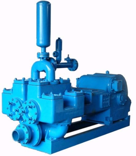
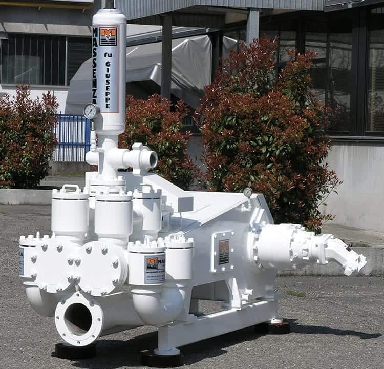
The most widely used mud pumps across the industry are Triplex Reciprocating Pumps. Their application has gained immense popularity with time because they are 30% lighter than duplex reciprocating pumps with relatively less operational cost. Moreover, through these pumps the discharge of mud is smooth and they are capable of moving large volume of mud at higher pressure.
Yes. We help you find the best mud pumps irrespective of your location. We simplify your search by connecting you with top mud pump manufacturers and mud pump companies in your location, according to your budget and business requirement.
Yes. We use third-party companies to provide best quotations for your shipment and inspection of manufactured goods. We make sure that you get quality products from the manufacturer at the best price.
The most widely used mud pumps across the industry are Triplex Reciprocating Pumps. Their application has gained immense popularity with time because they are 30% lighter than duplex reciprocating pumps with relatively less operational cost. Moreover, through these pumps the discharge of mud is smooth and they are capable of moving large volume of mud at higher pressure.
The different parts of a mud pump are Housing itself, Liner with packing, Cover plus packing, Piston and piston rod, Suction valve and discharge valve with their seats, Stuffing box (only in double-acting pumps), Gland (only in double-acting pumps), and Pulsation dampener. A mud pump also includes mud pump liner, mud pump piston, modules, hydraulic seat pullers along with other parts.
The wearing parts of a mud pump should be checked frequently for repairing needs or replacement. The wearing parts include pump casing, bearings, impeller, piston, liner, etc. Advanced anti-wear measures should be taken up to enhance the service life of the wearing parts. This can effectively bring down the project costs and improve production efficiency.
Ok! This is not an easy task, and I recommend that anyone thinking about doing it AT LEAST consider having the well pump identified as the failed component by a professional prior to undertaking it. In my case, the water in my house stopped working (on a Friday night, of course). I know my system pretty well and was able to determine that the fault in my system COULD NOT BE ANYTHING BUT my well pump motor before I took any action. Guess what? I called the plumber anyway. If nothing else, you"ll pay $60 to have your diagnosis confirmed and maybe even get an estimate that will provide you with the motivation to do the job on your own. (My estimate to pull and replace the well was $2400... By following these steps I was able to do the job myself for less than $400!)
The well used in this example is relatively shallow. It only runs about 100"-120" deep. Some wells can run to depths of hundreds (or thousands!) of feet. In the case of anything deeper than about 250" I would recommend that you have it pulled by a pro. Why? Because it"s HEAVY! And there are special tools that contractors have to lift the pump from that kind of depth. Look at it this way: Even if you have someone else pull the well, you can do the repair/replace action on your own once it"s out of the ground, and still save money. ;)
My well was dug about 25 years ago. One of the things that happens with older wells is that, over a period of several years, silt from the aquifer can seep into the bottom of the casing. That"s a bad thing. Why? Because the silt builds up to a depth that"s too close to the pump, and the pump ends up sucking up the silt and muck from the bottom of the well, and then pushes it into your house! (You"ll see the result of this kind of thing in the following pictures.)
The weight of the whole pump assembly hangs on the water hose that the pump uses to push water into the house. Up near the top the water tube hits what"s called a "pitless connector," where it makes a hard right turn toward the house.
See how the pump looks a bit like a bottle made of two pieces? The bottom part is the motor. The top part is the impeller that sucks the water out of the well and sends it to the house.
When one turns on the sink to wash one"s hands or when we flush a toilet, we tend to think that we"re pulling water directly from the well to do it. In actuality, we"re not!


 8613371530291