
weatherford 1600 mud pump specs and dimensions free sample

Weatherford products and services are subject to the Company’s standard terms and conditions, available on request or at weatherford.com. For more information contact an authorized Weatherford representative. Unless noted
otherwise, trademarks and service marks herein are the property of Weatherford and may be registered in the United States and/or other countries. Weatherford products named herein may be protected by one or more U.S. and/or
foreign patents. For more information, contact patents@weatherford.com. Specifications are subject to change without notice. Weatherford sells its products and services in accordance with the terms and conditions set forth in the
This website is using a security service to protect itself from online attacks. The action you just performed triggered the security solution. There are several actions that could trigger this block including submitting a certain word or phrase, a SQL command or malformed data.
This website is using a security service to protect itself from online attacks. The action you just performed triggered the security solution. There are several actions that could trigger this block including submitting a certain word or phrase, a SQL command or malformed data.
All the production and processing are strictly according to ISO 9001:2008 and API standard. At the same time, mature production technology ensuring the quality satisfy international request. We also welcome the third party inspection, such as BV, SGS and TUV.

A wide variety of mud pump weatherford options are available to you, such as 1 year, not available.You can also choose from new, mud pump weatherford,As well as from energy & mining, construction works , and machinery repair shops. and whether mud pump weatherford is 1.5 years, 6 months, or unavailable.

WE WROTE THE BOOK ON MUD PUMPS. AMC is a full service distributor of Weatherford Mud Pumps along with Weatherford’s new Ellis Williams mud pump line. We can offer either of these pumps under our distributorship agreement with Weatherford.
The EWECO Story. All EWECO pumps are manufactured in the USA. We cut our own patented herringbone gears which contribute to the longer life span of EWECO pumps. Our crankshafts are also a cut above. Instead of the automotive style, we make all eccentric crankshafts with anti-friction bearings for 25 percent greater efficiency. And while others use cast iron, EWECO’s longer-lasting crankshafts are constructed with forged steel.
Ellis Williams began his life’s work with mud pumps in 1942. Researching, designing, testing—he was relentless in his efforts to build pumps with greater efficiency and durability for rugged oilfield operations. Over the next 30 years, Ellis pioneered single-acting triplex pumps for oilfield drilling. He built many of these ground-breaking pumps for Brewster (the Skytop Brewster Triplex pumps). By the 1970s, most pumps in the industry were designed by Ellis Williams. Clearly, he was ready to design and build superior mud pumps under his own banner. And thus, in 1974, the Ellis Williams Company was born.
In addition to our renowned triplex pumps, EWECO is one of the few companies in the industry to offer quintuplex pumps. In drilling situations where size and weight are critical, these innovative pumps can be extremely cost efficient.
For the last 30-plus years, the name Ellis Williams has been synonymous with efficient, innovative and extremely durable pumps. We originated the use of all-roller bearings, eccentric crankshaft and internal gears. Ellis Williams wrote the AGMA Standard (424.01) Practice for Helical and Herringbone Gearing for Oilfield Mud Pumps. And we have continued to design and build drilling pumps without comparison in the industry.
No matter which models are right for your projects, you can depend on EWECO for quality, efficiency and longevity. Indeed, EWECO pumps deliver 95-99 percent mechanical efficiency. A big advantage for your company, and for the environment, too.
Today, Ellis Williams Engineering Company (EWECO) is a full-service engineering and consulting company. Specializing in pumps and pump packages, we bring to our customers over 130 years of experience. We also provide consultation on pump applications, field service analysis and pump maintenance.
From design to construction, EWECO pumps are intended to meet tough and exacting standards. Manufactured in our own machine shop, every EWECO pump is fabricated with a high-strength, heat-treated alloy steel power frame. This method allows for easy modification of pump designs to meet your custom applications.
At EWECO, we wrote the book on mud pumps. But our book is a work in progress. As dynamic and rewarding as our history has been, our most exciting chapters lie ahead.
The EWECO Advantage. It’s all about performance. At EWECO, our pumps are designed to deliver maximum performance with minimum pump weight. For us, that means greater horsepower per pound. Higher horsepower pumps—with a smaller footprint and lighter weight—shorten completion time. And because of superior design, EWECO pumps have a longer life expectancy and work a lot harder. In fact, our pumps are rated for 24 houra-day true continuous duty. 1
With over 125 utilization methods, EWECO can provide complete pump packages, including prime movers, controls, manifolds, piping, accessories and so on. We can mount equipment on heavy-duty oilfield or industrial type skids. We can also supply portable-trailer mounted units, top drive electric motor-driven units, or whatever your particular requirements demand. EWECO includes the suction stabilizer on all units. We can also provide each with suction equipment, including discharge dampeners, gauges, relief valves, charge pumps and the like. Regardless of the size or scope of your project, EWECO has the experience and resources to handle the job. At the same time, you can count on us for fast, flexible and personal service.
The “EH” series of lightweight and Light-Lift continuous duty triplex pumps, 800 hp-1600 hp are also available. These pumps are excellent choices for helicopter lift, trailer-mounted packages, offshore platforms and any application where weight and size must be kept to a minimum.
Pinions, gears, crankshafts and fluid end modules made from high-strength, heat-treated, forged- alloy steel Versatility of engineering and design to accommodate: Various internal gear ratios, all sizes, all AGMA 424.01 Balanced, forged-alloy steel eccentric crankshafts, machined between centers on all axes 2
Horsepower for Single Acting Pump= (GPM)(PD)(100) - (GPM)(Ps)(Em-5%) (1714)(Em) (1714)(100) Horsepower for Double Acting Pump= (GPM)(Pd-Ps)(100) (1714)(Em) Nomenclature: Pd Ps Em
= Pump Discharge Pressure (PSI) = Pump Suction Pressure (PSI) = Pump Mechanical Efficiency (in decimal form: i.e. (0.9), (0.85)) GPM = U.S. Gallons Per Minute RPM = Revolutions Per Minute Of Pump Crankshaft
Torque = (HP)(5252) RPM Degrees Celsius (°C) = (F-32°)(5/9)° Degrees Farenheit (°F) = (9/5)°C + 32° Belt Length (Pitch Diameter Pump Sheave + Pitch Diameter Driver)
AMC is a full service distributor of Weatherford Mud Pumps along with Weatherford’s new Ellis Williams mud pump line. We can offer either of these pumps under our distributorship agreement with Weatherford. FOR MORE INFORMATION: If you’d like to know more about EWECO’s superior, “Made-In-The USA” pumps and pump packages, give us a call, or visit our web site. You’ll not only be impressed with our great mud pumps; you’ll also appreciate the way we do business.
Ellis Williams Engineering Company • 339 Magnolia Business Park Drive • Magnolia, Texas 77354 AMC EQUIPMENT LOCATION * 11951-C FM 529 *Houston, TX 77041 281-252-PUMP (7867) • Toll FREE: 866-94EWECO (39326) • Fax: 281-766-1982 • www.eweco.com PH: 281-598-9980 * FX: 281-598-9985 * www.appmach.com © 2008 Weatherford. All rights reserved. 5992.00
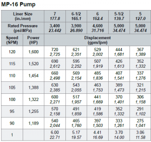
Note: *Cased Hole Only. The Chart above is a guide-line only and should be used as a rule of thumb; the final decision is that of the Customer; 4” Pin-up drill pipe is an option inside 7” casing, discuss
These figures do not constitute a guarantee, actual or implied; they are meant to serve as a guide only, and appropriate allowance must be made in use, as a safety factor.
The tightening torque values were calculated assuming Itcolube or similar zinc-based grease on all threads and shoulders. Multiply chart values by .1382
WARNING! All jarring and pulling loads shown in the manual assume that the force is acting alone and is essentially along with major axis of the tool. If
torque and tension or bending and tension are used together, the resulting combined stresses may lead to failure at substantially less than rated loads.
Users of jars and bumper subs should be aware that milling or drilling operations may develop stresses in these tools that are more complex than the simple torsional and tensile values
The necessity for milling is recognized and this is not intended to advise against such operations, but merely to caution the user of possible dangers when rotating under the conditions

The invention relates generally to offshore drilling systems which are employed for drilling subsea wells. More particularly, the invention relates to an offshore drilling system which maintains a dual pressure gradient, one pressure gradient above the well and another pressure gradient in the well, during a drilling operation.
Deep water drilling from a floating vessel typically involves the use of a large- diameter marine riser, e.g. a 21 -inch marine riser, to connect the floating vessel"s surface equipment to a blowout preventer stack on a subsea wellhead. The floating vessel may be moored or dynamically positioned at the drill site. However, dynamically-positioned drilling vessels are predominantly used in deep water drilling. The primary functions of the marine riser are to guide the drill string and other tools from the floating vessel to the subsea wellhead and to conduct drilling fluid and earth-cuttings from a subsea well to the floating vessel. The marine riser is made up of multiple riser joints, which are special casings with coupling devices that allow them to be interconnected to form a tubular passage for receiving drilling tools and conducting drilling fluid. The lower end of the riser is normally releasably latched to the blowout preventer stack, which usually includes a flexible joint that permits the riser to angularly deflect as the floating vessel moves laterally from directly over the well. The upper end of the riser includes a telescopic joint that compensates for the heave of the floating vessel. The telescopic joint is secured to a drilling rig on the floating vessel via cables that are reeved to sheaves on riser tensioners adjacent the rig"s moon pool. The riser tensioners are arranged to maintain an upward pull on the riser. This upward pull prevents the riser from buckling under its own weight, which can be quite substantial for a riser extending over several hundred feet. The riser tensioners are
adjustable to allow adequate support for the riser as water depth and the number of riser joints needed to reach the blowout preventer stack increases. In very deep water, the weight of the riser can become so great that the riser tensioners would be rendered ineffective. To ensure that the riser tensioners work effectively, buoyant devices are attached to some of the riser joints to make the riser weigh less when submerged in water. The buoyant devices are typically steel cylinders that are filled with air or plastic foam devices.
The maximum practical water depth for current drilling practices with a large diameter marine riser is approximately 7,000 feet. As the need to add to energy reserves increases, the frontiers of energy exploration are being pushed into ever deeper waters, thus making the development of drilling techniques for ever deeper waters increasingly more important. However, several aspects of current drilling practices with a conventional marine riser inherently limit deep water drilling to water depths less than approximately 7,000 feet. The first limiting factor is the severe weight and space penalties imposed on a floating vessel as water depth increases. In deep water drilling, the drilling fluid or mud volume in the riser constitutes a majority of the total mud circulation system and increases with increasing water depth. The capacity of the 21 -inch marine riser is approximately 400 barrels for every 1,000 feet. It has been estimated that the weight attributed to the marine riser and mud volume for a rig drilling at a water depth of 6,000 feet is 1,000 to 1,500 tons. As can be appreciated, the weight and space requirements for a drilling rig that can support the large volumes of fluids required for circulation and the number of riser joints required to reach the seafloor prohibit the use of the 21 -inch riser, or any other large-diameter riser, for drilling at extreme water depths using the existing offshore drilling fleet.
water waves and can result in high levels of energy being imparted on the drilling vessel and the riser, especially when the bottom end of the riser is disconnected from the blowout preventer stack. The dynamic stresses due to the interaction between the heave of the drilling vessel and the riser can result in high compression waves that may exceed the capacity of the riser.
In water depths 6,000 feet and greater, the 21 -in riser is flexible enough that angular and lateral deflections over the entire length of the riser will occur due to the water currents acting on the riser. Therefore, in order to keep the riser deflections within acceptable limits during drilling operations, tight station keeping is required. Frequently, the water currents are severe enough that station keeping is not sufficient to permit drilling operations to continue. Occasionally, water currents are so severe that the riser must be disconnected from the blowout preventer stack to avoid damage or permanent deformation. To prevent frequent disconnection of the riser, an expensive fairing may have to be deployed or additional tension applied to the riser. From an operational standpoint, a fairing is not desirable because it is heavy and difficult to install and disconnect. On the other hand, additional riser tensioners may over-stress the riser and impose even greater loads on the drilling vessel.
A third limiting factor is the difficulty of retrieving the riser in the event of a storm. Based on the large forces that the riser and the drilling vessel are already subjected to, it is reasonable to conclude that neither the riser nor the drilling vessel would be capable of sustaining the loads imposed by a hurricane. In such a condition, if the drilling vessel is a dynamically positioned type, the drilling vessel will attempt to evade the storm. Storm evasion would be impossible with 10,000 feet of riser hanging from the drilling vessel. Thus, in such a situation, the riser would have to be pulled up entirely.
In addition, before disconnecting the riser from the blowout preventer stack, operations must take place to condition the well so that the well may be safely abandoned. This is required because the well depends on the hydrostatic pressure of the mud column extending from the top end of the riser to the bottom of the well to
overcome the pore pressures of the formation. When the mud column in the riser is removed, the hydrostatic pressure gradient is significantly reduced and may not be sufficient to prevent formation fluid influx into the well. Operations to contain well pressure may include setting a plug, such as a storm packer, in the well and closing the blind ram in the blowout preventer stack.
After the storm, the drilling vessel would return to the drill site and deploy the riser to reconnect and resume drilling. In locations like Gulf of Mexico where the average annual number of hurricanes is 2.8 and the maximum warning time of an approaching hurricane is 72 hours, it would be necessary to disconnect and retrieve the riser every time there is a threat of hurricane in the vicinity of the drilling location. This, of course, would translate to huge financial losses to the well operator.
A fourth limiting factor, relates to emergency disconnects such as when a dynamically positioned drilling vessel experiences a drive off. A drive off is a condition when a floating drilling vessel loses station keeping capability, loses power, is in imminent danger of colliding with another marine vessel or object, or experiences other conditions requiring rapid evacuation from the drilling location. As in the case of the storm disconnect, well operations are required to condition the well for abandoning. However, there is usually insufficient time in a drive off to perform all of the necessary safe abandonment procedures. Typically, there is only sufficient time to hang off the drill string from the pipe/hanging rams and close the shear/blind rams in the blowout preventer before disconnecting the riser from the blowout preventer stack.
The well hydrostatic pressure gradient derived from the riser height is trapped below the closed blind rams when the riser is disconnected. Thus, the only barrier to the influx of formation fluid into the well is the closed blind rams since the column of mud below the blind rams is insufficient to prevent influx of formation fluid into the well. Prudent drilling operations require two independent barriers to prevent loss of well control. When the riser is disconnected from the blowout preventer stack, large volumes of mud will be dumped onto the seafloor. This is undesirable from both an economic and environmental standpoint.
A fifth limiting factor relates to marginal well control and the need for numerous casing points. In any drilling operation, it is important to control the influx of formation fluid from subsurface formations into the well to prevent blowout. Well control procedures typically involve maintaining the hydrostatic pressure of the drilling fluid column above the "open hole" formation pore pressure but, at the same time, not above the formation fracture pressure. In drilling the initial section of the well, the hydrostatic pressure is maintained using seawater as the drilling fluid with the drilling returns discharged onto the seafloor. This is possible because the pore pressures of the formations near the seafloor are close to the seawater hydrostatic pressure at the seafloor. While drilling the initial section of the well with seawater, formations having pore pressures greater than the seawater hydrostatic pressure may be encountered. In such situations, formation fluids may flow freely into the well. This uncontrolled flow of formation fluids into the well may be so great as to cause washouts of the drilled hole and, possibly, destroy the drilling location. To prevent formation fluid flow into the well, the initial section of the well may be drilled with weighted drilling fluids. However, the current practice of discharging fluid to the seafloor while drilling the initial section of the well does not make this option very attractive. This is because the large volumes of drilling fluids dumped onto the seafloor are not recovered. Large volumes of unrecovered weighted drilling fluids are expensive and, possibly, environmentally undesirable.
After the initial section of the well is drilled to an acceptable depth, using either seawater or weighted drilling fluid, a conductor casing string with a wellhead is run and cemented in place. This is followed by running a blowout preventer stack and marine riser to the seafloor to permit drilling fluid circulation from the drilling vessel to the well and back to the drilling vessel in the usual manner.
In geological areas characterized by rapid sediment deposition and young sediments, fracture pressure is a critical factor in well control. This is because fracture pressure at any point in the well is related to the density of the sediments resting above that point combined with the hydrostatic pressure of the column of seawater above.
These sediments are significantly influenced by the overlying body of water and the circulating mud column need only be slightly denser than seawater to fracture the formation. Fortunately, because of the higher bulk density of the rock, the fracture pressure rapidly increases with the depth of penetration below the seafloor and will present a less serious problem after the first few thousand feet are drilled. However, abnormally high pore pressures which are routinely encountered up to 2,000 feet below the seafloor continue to present a problem both when drilling the initial section of the well with seawater and when drilling beyond the initial section of the well with seawater or weighted drilling fluid. The challenge then becomes balancing the internal pressures of the formation with the hydrostatic pressure of the mud column while continuing drilling of the well. The current practice is to progressively run and cement casings, the next inside the previous, into the hole to protect the "open hole" sections possessing insufficient fracture pressure while allowing weighted drilling fluids to be used to overcome formation pore pressures. It is important that the well be completed with the largest practical casing through the production zone to allow production rates that will justify the high-cost of deep-water developments. Production rates exceeding 10,000 barrels per day are common for deep-water developments, and too small a production casing would limit the productivity of the well, making it uneconomical to complete. The number of casings run into the hole is significantly affected by water depth.
The multiple casings needed to protect the "open hole" while providing the largest practical casing through the production zone requires that the surface hole at the seafloor be larger. A larger surface hole in turn requires a larger subsea wellhead and blowout preventer stack and a larger blowout preventer stack requires a larger marine riser. With a larger riser, more mud is required to fill the riser and a larger drilling vessel is required to carry the mud and support the riser. This cycle repeats itself as water depth increases.
It has been identified that the key to breaking this cycle lies in reducing the hydrostatic pressure of the mud in the riser to that of a column of seawater and providing mud with sufficient weight in the well to maintain well control. Various concepts have
been presented in the past for achieving this feat; however, none of these concepts known in the prior art have gained commercial acceptance for drilling in ever deeper waters. These concepts can be generally grouped into two categories: the mud lift drilling with a marine riser concept and the riserless drilling concept. The mud lift drilling with a marine riser concept contemplates a dual-density mud gradient system which includes reducing the density of the mud returns in the riser so that the return mud pressure at the seafloor more closely matches that of seawater. The mud in the well is weighted to maintain well control. For example, U.S. Patent No. 3,603,409 to Watkins et al. and U.S. Patent No. 4,099,583 to Maus et al. disclose methods of injecting gas into the mud column in the marine riser to lighten the weight of the mud.
The riserless drilling concept contemplates eliminating the large-diameter marine riser as a return annulus and replacing it with one or more small-diameter mud return lines. For example, U.S. Patent No. 4,813,495 to Leach removes the marine riser as a return annulus and uses a centrifugal pump to lift mud returns from the seafloor to the surface through a mud return line. A rotating head isolates the mud in the well annulus from the open seawater as the drill string is run in and out of the well.
Drilling rates are significantly affected by the magnitude of the difference between formation pore pressure and mud column pressure. This difference, commonly called "overbalance", is adjusted by changing the density of the mud column. Overbalance is estimated as the additional pressure required to prevent the well from kicking, either during drilling or when pulling a drill string out of the well. This overbalance estimate usually takes into account factors like inaccuracies in predicting formation pore pressures and pressure reductions in the well as a drill string is pulled from the well. Typically, a minimum of 300 to 700 psi overbalance is maintained during drilling operations. Sometimes the overbalance is large enough to damage the formation.
The effect of overbalance on drilling rates varies widely with the type of drill bit, formation type, magnitude of overbalance, and many other factors. For example, in a typical drill bit and formation combination with a drilling rate of 30 feet per hour and an overbalance of 500 psi, it is common for the drilling rate to double to 60 feet per hour if
the overbalance is reduced to zero. An even greater increase in drilling rate can be achieved if the mud column pressure is decreased to an underbalanced condition, i.e. mud column pressure is less than formation pressure. Thus, to improve drilling rates, it may be desirable to drill a well in an underbalanced mode or with a minimum of overbalance. In conventional drilling operations, it is impractical to reduce the mud density to allow faster drilling rates and then increase the mud density to permit tripping the drill string. This is because the circulation time for the complete mud system lasts for several hours, thus making it expensive to repeatedly decrease and increase mud density. Furthermore, such a practice would endanger the operation because a miscalculation could result in a kick.
In general, in one aspect, a positive-displacement pump comprises multiple pumping elements, each pumping element comprising a pressure vessel with a first and a second chamber and a separating member disposed between the first and second chambers. The first chambers and the second chambers are hydraulically connected to receive and discharge fluid, wherein the separating members move within the pressure vessels in response to pressure differential between the first and second chambers. A valve assembly having suction and discharge valves communicates with the first chambers. The suction and discharge valves are operable to permit fluid to alternately flow into and out of the first chambers. A hydraulic drive alternately supplies hydraulic fluid to and withdraws hydraulic fluid from the second chambers such that the fluid discharged from the first chambers is substantially free of pulsation.
FIG. 2A is a detailed view of the well control assembly shown in FIG. 1. FIG. 2B is a detailed view of the mud lift module shown in FIG. 1. FIG. 2C is a detailed view of the pressure-balanced mud tank shown in FIG. 1.
FIGS. 3 A and 3B are cross sections of non-rotating subsea diverters. FIGS. 4A-4F are cross sections of rotating subsea diverters. FIG. 5 is a cross section of a wiper.
FIG. 8 is an elevation view of a subsea mud pump. FIG. 9A is a cross section of a diaphragm pumping element. FIG. 9B is a cross section of a piston pumping element.
FIG. 16 is a diagram of a mud circulation system for the offshore drilling system shown in FIG. 1. FIG. 17 is a graph of depth versus pressure for a well drilled in a water depth of
FIG. 20A is a graph of depth versus pressure for a well drilled in a water depth of 5,000 feet for a dual-density mud gradient system which has a mudline pressure less than seawater pressure.
FIG. 21 illustrates the offshore drilling system of FIG. 1 with a mud lift module mounted on the seafloor. FIGS. 22A and 22B are elevation views of retrievable subsea components of the offshore drilling system shown in FIG. 21.
FIG. 26 is a top view of another embodiment of the return line riser shown in FIG. 23. FIG. 27 illustrates the offshore drilling system of FIG. 1 without a marine riser and with a mud lift module mounted on the seafloor.
DETAILED DESCRIPTION FIG. 1 illustrates an offshore drilling system 10 where a drilling vessel 12 floats on a body of water 14 which overlays a pre-selected formation. The drilling vessel 12 is dynamically positioned above the subsea formation by thrusters 16 which are activated by on-board computers (not shown). An array of subsea beacons (not shown) on the seafloor 17 sends signals which are indicative of the location of the drilling vessel 12 to hydrophones (not shown) on the hull of the drilling vessel 12. The signals received by the hydrophones are transmitted to on-board computers. These on-board computers process the data from the hydrophones along with data from a wind sensor and other auxiliary position-sensing devices and activate the thrusters 16 as needed to maintain the drilling vessel 12 on station. The drilling vessel 12 may. also be maintained on station by using several anchors that are deployed from the drilling vessel to the seafloor. Anchors, however, are generally practical if the water is not too deep.
A drilling rig 20 is positioned in the middle of the drilling vessel 12, above a moon pool 22. The moon pool 22 is a walled opening that extends through the drilling vessel 12 and through which drilling tools are lowered from the drilling vessel 12 to the seafloor 17. At the seafloor 17, a conductor pipe 32 extends into a well 30. A conductor housing 33, which is attached to the upper end of the conductor pipe 32, supports the conductor pipe 32 before the conductor pipe 32 is cemented in the well 30. A guide structure 34 is installed around the conductor housing 33 before the conductor housing 33 is run to the seafloor 17. A wellhead 35 is attached to the upper end of a surface pipe 36 that extends through the conductor pipe 32 into the well 30. The wellhead 35 is of conventional design and provides a method for hanging additional casing strings in the well 30. The wellhead 35 also forms a structural base for a wellhead stack 37.
The wellhead stack 37 includes a well control assembly 38, a mud lift module 40, and a pressure-balanced mud tank 42. A marine riser 52 between the drilling rig 20 and the wellhead stack 37 is positioned to guide drilling tools, casing strings, and other equipment from the drilling vessel 12 to the wellhead stack 37. The lower end of the marine riser 52 is releasably latched to the pressure-balanced mud tank 42, and the upper end of the marine riser 52 is secured to the drilling rig 20. Riser tensioners 54 are provided to maintain an upward pull on the marine riser 52. Mud return lines 56 and 58, which may be attached to the outside of the marine riser 52, connect flow outlets (not shown) in the mud lift module 40 to flow ports in the moon pool 22. The flow ports in the moon pool 22 serve as an interface between the mud return lines 56 and 58 and a mud return system (not shown) on the drilling vessel 12. The mud return lines 56 and 58 are also connected to flow outlets (not shown) in the well control assembly 38, thus allowing them to be used as choke/kill lines. Alternatively, the mud return lines 56 and 58 may be existing choke/kill lines on the riser.
A drill string 60 extends from a derrick 62 on the drilling rig 20 into the well 30 through the marine riser 52 and the wellhead stack 37. Attached to the end of the drill string 60 is a bottom hole assembly 63, which includes a drill bit 64 and one or more drill collars 65. The bottom hole assembly 63 may also include stabilizers, mud motor, and
other selected components required for drilling a planned trajectory, as is well known in the art. During normal drilling operations, the mud pumped down the bore of the drill string 60 by a surface pump (not shown) is forced out of the nozzles of the drill bit 64 into the bottom of the well 30. The mud at the bottom of the well 30 rises up the well annulus 66 to the mud lift module 40, where it is diverted to the suction ends of subsea mud pumps (not shown). The subsea mud pumps boost the pressure of the returning mud flow and discharge the mud into the mud return lines 56 and/or 58. The mud return lines 56 and/or 58 then conduct the discharged mud to the mud return system (not shown) on the drilling vessel 12. The drilling system 10 is illustrated with two mud return lines 56 and 58, but it should be clear that a single mud return line or more than two mud return lines may also be used. Clearly the diameter and number of the return lines will affect the pumping requirements for the subsea mud pumps in the mud lift module 40. The subsea mud pumps must provide enough pressure to the returning mud flow to overcome the frictional pressure losses and the hydrostatic head of the mud column in the return lines. The wellhead stack 37 includes subsea diverters (not shown) which seal around the drill string 60 and form a separating barrier between the riser 52 and the well annulus 66. The riser 52 is filled with seawater so that the hydrostatic pressure of the fluid column at the seafloor or mudline or separating barrier formed by the subsea diverters is that of seawater. Filling the riser with seawater, as opposed to mud, reduces the riser tension requirements. The riser may also be filled with other fluids which have a lower specific gravity than the mud in the well annulus.
Well Control Assembly FIG. 2A shows the components of the well control assembly 38 which was previously illustrated in FIG. 1. As shown, the well control assembly 38 includes a lower marine riser package (LMRP) 44 and a subsea blowout preventer (BOP) stack 46. The BOP stack 46 includes a pair of dual ram preventers 70 and 72. However, other combinations, such as, a triple ram preventer combined with a single ram preventer may
be used. Additional preventers may also be required depending on the preferences of the drilling operator. The ram preventers are equipped with pipe rams for sealing around a pipe and shear/blind rams for shearing the pipe and sealing the well. The ram preventers 70 and 72 have flow ports 76 and 78, respectively, that may be connected to choke/kill lines (not shown). A wellhead connector 88 is secured to the lower end of the ram preventer 70. The wellhead connector 88 is adapted to mate with the upper end of the wellhead 35 (shown in FIG. 1).
The LMRP 44 includes annular preventers 90 and 92 and a flexible joint 94. However, the LMRP 44 may take on other configurations, e.g., a single annular preventer and a flexible joint. The annular preventers 90 and 92 have flow ports 98 and 100 that may be connected to choke/kill lines (not shown). The lower end of the annular preventer 90 is connected to the upper end of the ram preventers 72 by a LMRP connector 93. The flexible joint 94 is mounted on the upper end of the annular preventer 92. A riser connector 114 is attached to the upper end of the flexible joint 94. The riser connector 114 includes flow ports 113 which may be hydraulically connected to the flow ports 76, 78, 98, and 100. The LMRP 44 includes control modules (not shown) for operating the ram preventers 70 and 72, the annular preventers 90 and 92, various connectors and valves in the wellhead stack 37, and other controls as needed. Hydraulic fluid is supplied to the control modules from the surface through hydraulic lines (not shown) that may be attached to the outside of the riser 52 (shown in FIG. 1).
Mud lift module FIG. 2B shows the components of the mud lift module 40 which was previously illustrated in FIG. 1. As shown, the mud lift module 40 includes subsea mud pumps 102, a flow tube 104, a non-rotating subsea diverter 106, and a rotating subsea diverter 108. The lower end of the flow tube 104 includes a riser connector 110 which is adapted to mate with the riser connector 114 (shown in FIG. 2 A) at the upper end of the flexible joint 94. When the riser connector 110 mates with the riser connector 114, the flow ports 111 in the riser connector 110 are in communication with the flow ports 113 (shown in
FIG. 2 A) in the riser connector 114. A riser connector 112 is mounted at the upper end of the subsea diverter 108. The flow ports 111 in the riser connector 110 are connected to flow ports 116 in the riser connector 112 by pipes 118 and 120, and the pipes 118 and 120 are in turn hydraulically connected to the discharge ends of the subsea mud pumps 102. The suction ends of the subsea mud pumps 102 are hydraulically connected to flow outlets 125 in the flow tube 104.
The subsea diverters 106 and 108 are arranged to divert mud from the well annulus 66 (shown in FIG. 1) to the suction ends of the subsea mud pumps 102. The diverters 106 and 108 are also adapted to slidingly receive and seal around a drill string, e.g., drill string 60. When the diverters seal around the drill string 60, the fluid in the flow tube 104 or below the diverters is isolated from the fluid in the riser 52 (shown in FIG. 1) or above the diverters. The diverters 106 and 108 may be used alternately or together to sealingly engage a drill string and, thereby, isolate the fluid in the annulus of the riser 52 from the fluid in the well annulus 66. It should be clear that either the diverter 106 or 108 may be used alone as the separating medium between the fluid in the riser 52 and the fluid in the well annulus 66. A rotating blowout preventer (not shown), which could be included in the well control assembly 38 (shown in FIG. 2 A), may also be used in place of the diverters. The diverter 108 may also be mounted on the annular preventer 92 (shown in FIG. 2 A), and mud flow into the suction ends of the subsea pumps 102 may be taken from a point below the diverter.
Non-rotating subsea diverter FIG. 3 A shows a vertical cross section of the non-rotating subsea diverter 106 which was previously illustrated in FIG. 2B. As shown, the non-rotating subsea diverter 106 includes a head 126 that is fastened to a body 128 by bolts 130. However, other means, such as a screwed or radial latched connection, may be used in place of bolts 130. The body 128 has a flange 131 that may be bolted to the upper end of the flow tube 104, as shown in FIG. 2B. The head 126 and body 128 are provided with bores 132 and 134, respectively. The bores 132 and 134 form a passageway 136 for receiving a drill string,
e.g., drill string 60. The body 128 has a closing cavity 138 and an opening cavity 139. A piston 140 is arranged to move inside the cavities 138 and 139 in response to pressure of the hydraulic fluid fed into these cavities. At the upper end of the body 128 is a sleeve 142 and cover 143 which guide the piston 140 as it moves inside the cavities 138 and 139.
The cavity 138 is enveloped by the body 128, the piston 140, and the sleeve 142. The cavity 139 is enveloped by the body 128, the piston 140, and cover 143. As the piston 140 moves inside the cavities 138 and 139, seal rings 144 contain hydraulic fluid in the cavities. The sleeve 142 is provided with holes 148 for venting fluid out of a cavity 145 below the piston 140. A resilient, elastomeric, toroid-shaped, sealing element 150 is located between the upper end of the piston 140 and a tapered portion 152 of the internal wall of the head 126. The sealing element 150 may be actuated to seal around a drill string, e.g., drill string 60, in the passageway 136.
The piston 140 moves downwardly to open the passageway 136 when hydraulic fluid is supplied to the opening cavity 139. As illustrated in the left half of the drawing, when the piston 140 sits on the body 128, the sealing element 150 does not extrude into the passageway 136 and the diverter 106 is fully open. When the diverter 106 is fully open, the passageway 136 is large enough to receive a bottom hole assembly and other drilling tools. When hydraulic fluid is fed into the cavity 138, the piston 140 moves upwardly to close the diverter 106. As illustrated in the right half of the drawing, when the piston 140 moves upwardly, the sealing element 150 is extruded into the passageway 136. If there is a drill string in the passageway 136, the extruded sealing element 150 would contact the drill string and seal the annulus between the passageway 136 and the drill string. FIG. 3B shows a vertical cross section of another non-rotating subsea diverter, i.e., subsea diverter 270, that may be used in place of the non-rotating subsea diverter 106. The subsea diverter 270 includes a housing body 272 with flanges 274 and 276 which are provided for connection with other components of the wellhead stack 37, e.g., the flow tube 104 and the subsea diverter 108 (shown in FIG. 2B). The housing body
272 is provided with a bore 278 and pockets 280. The pockets 280 are distributed along a circumference of the housing body 272. Inside each pocket 280 is a retractable landing shoulder 282 and a lock 284. Hydraulic actuators 285 are provided to actuate the locks 284 to engage a retrievable stripper element 286 which is disposed within the bore 278 of the housing body 272.
The stripper element 286 includes a stripper rubber 288 that is bonded to a metal body 290. The locks 284 slide into recesses 291 in the metal body 290 to lock the metal body 290 in place inside the housing body 272. A seal 292 on the metal body 290 forms a seal between the housing body 272 and the metal body 290. The stripper rubber 288 sealingly engages a drill string that is received inside the bore 278 while permitting the drill string to rotate and move axially inside the bore 278. The stripper rubber 288 does not rotate with the drill string so the rubber 288 is subjected to friction forces associated with both the rotational and vertical motions of the drill string. The stripper element 286 may be carried into and out of the housing body 272 on a handling tool which may be positioned above the bottom hole assembly of the drill string.
Rotating subsea diverter FIG. 4A shows a vertical cross section of the rotating subsea diverter 108 which was previously illustrated in FIG. 2B. As shown, the rotating subsea diverter 108 includes a housing body 162 with flanges 164 and 166. The flange 164 is arranged to mate with the upper end of the diverter 106 (shown in FIG. 3 A). The housing body 162 is provided with a bore 168 and pockets 170. The pockets 170 are distributed along a circumference of the housing body 162. Inside each pocket 170 is a retractable landing shoulder 174 and a lock 176. Hydraulic actuators 177 are provided to operate the locks 176. Although the lock 176 is shown as being hydraulically actuated, it should be clear that the lock 176 may be actuated by other means, e.g., the lock 176 may be radially loaded with springs. The lock 176 may also incorporate a mechanism that permits intervention by a remote operated vehicle (ROV) such as a "T" handle in series with the actuator for gripping by the ROV manipulator.
A retrievable spindle 178 is disposed in the bore 168 of the housing body 162. The spindle 178 has an upper portion 180 and a lower portion 182. The upper portion 180 has recesses 181 into which the locks 176 may slide to lock the upper portion 180 in place inside the housing body 162. A seal 183 on the upper portion 180 seals between the housing body 162 and the upper portion 180. A bearing assembly 184 is attached to the upper portion 180. The bearing assembly 184 has bearings which support the lower portion 182 of the spindle 178 for rotation inside the housing body 162. A stripper rubber 185 is bonded to the lower portion 182 of the spindle 178. The stripper rubber 185 rotates with and sealingly engages a drill string (not shown) that is received in the bore 168 while permitting the drill string to move vertically.
In operation, the spindle 178 is carried into the housing body 162 on a handling tool that is mounted on the drill string. When the spindle 178 lands on the shoulder 174, the drill string is rotated until the locks 176 are aligned with the recesses 181 in the upper portion 180 of the spindle 178. Then the hydraulic actuators 177 are operated to push the locks 176 into the recesses 181. The stripper rubber 185 seals against the drill string while allowing the drill string to be lowered into the well. During drilling, friction between the rotating drill string and the stripper rubber 185 provides sufficient force to rotate the lower portion 182 of the spindle 178. While the lower portion 182 is rotated, the stripper rubber 185 is only subjected to the friction forces associated with the vertical motion of the drill string. This has the effect of prolonging the wear life of the stripper rubber 185. When the drill string is pulled out of the well, the hydraulic actuators 177 may be operated to release the locks 176 from the recesses 181 so that the handling tool on the drill string can engage the spindle 178 and pull the spindle 178 out of the housing body 162. FIG. 4B shows a vertical cross section of another rotating subsea diverter, i.e., rotating subsea diverter 186, that may be used in place of the rotating subsea diverter 108. The subsea diverter 186 includes a retrievable spindle 188 which is disposed in a housing body 190. The spindle 188 includes two opposed stripper rubbers 192 and 194. The stripper rubber 192 is oriented to effect a seal around a drill string when the pressure
above the spindle 188 is greater than the pressure below the spindle 188. The spindle 188 includes two bearing assemblies 196 and 198 which support the stripper rubbers 192 and 194, respectively, for rotation.
FIG. 4C shows a vertical cross section of another rotating subsea diverter, i.e., rotating subsea diverter 1710, which may be used in place of the rotating subsea diverter 108 and/or the non-rotating subsea diverter 106. The rotating subsea diverter 1710 includes a head 1712 which has a vertical bore 1714 and a body 1716 which has a vertical bore 1718. The head 1712 and the body 1716 are held together by a radial latch 1720 and locks 1722. The radial latch 1720 is disposed in an annular cavity 1724 in the body 1716 and is secured to the head 1712 by a series of interlocking grooves 1726. The locks 1722 are distributed in pockets 1730 along a circumference of the body 1716. As shown in FIG. 4D, each lock 1722 includes a clamp 1732 which is secured to the radial latch 1720 by a screw 1734. A plug 1736 and a seal 1738 are provided to keep fluid and debris out of each pocket 1730. A retrievable spindle assembly 1740 is disposed in the vertical bores 1714 and
1718. The spindle assembly 1740 includes a spindle housing 1742 which is secured to the body 1716 by an elastomer clamp 1744. The elastomer clamp 1744 is disposed in an annular cavity 1746 in the body 1716 and includes an inner elastomeric element 1748 and an outer elastomeric element 1750. The inner elastomeric element 1748 may be made of a different material than the outer elastomeric element 1750. The outer elastomeric element 1750 has an annular body 1752 with flanges 1754. A ring holder 1756 is arranged between the flanges 1754 to support and add stiffness to the outer elastomeric element 1750. The inner elastomeric element 1748 is formed in the shape of a torus and arranged within the outer elastomeric element 1750. When fluid pressure is fed to the outer elastomeric element 1750 through a port (not shown) in the body 1716, the outer elastomeric element 1750 inflates and applies force to the inner elastomeric element 1748, extruding the inner elastomeric element 1748 to engage and seal against the spindle housing 1742.
As shown in FIG. 4E, the spindle assembly 1740 further comprises a spindle 1760 which extends through the spindle housing 1742. The spindle 1760 is suspended in the spindle housing 1742 by bearings 1762 and 1764. The bearing 1762 is secured between the spindle housing 1742 and the spindle 1760 by a bearing cap 1765. The spindle housing 1742, the spindle 1760, and the bearings 1762 and 1764 define a chamber 1768 which holds lubricating fluid for the bearings. The bearing cap 1765 may be removed to access the chamber 1768. Pressure intensifiers 1766 are provided to boost the pressure in the chamber 1768 as necessary so that the pressure in the chamber 1768 balances or exceeds the pressure above and below the spindle 1760. Referring back to FIG. 4C, the spindle 1760 includes an upper packer element 1772, a lower packer element 1774, and a central passageway 1776 for receiving a drill string, e.g., drill string 1770.
A landing shoulder 1778 is disposed in a pocket 1780 in the body 1716. The landing shoulder 1778 may be extended out of the pocket 1780 or retracted into the pocket 1780 by a hydraulic actuator 1782. When the landing shoulder 1778 is extended out of the pocket 1780, it prevents the spindle assembly 1740 from falling out of the body 1716. As shown in FIG. 4F, the hydraulic actuator 1782 comprises a cylinder 1784 which houses a piston 1786. The cylinder 1784 is arranged in a cavity 1788 on the outside of the body 1716 and held in place by a cap 1790. A threaded connection 1792 attaches one side of the piston 1786 to the landing shoulder 1778. The piston 1786 extends from the landing shoulder 1778 into a cavity 1794 in the cap 1790. The cap 1790 and the cylinder 1784 include ports 1796 and 1798 through which fluid may be fed into or discharged from the cavity 1794 and the interior of the cylinder 1784, respectively. Dynamic seals 1800 are provided on the piston 1786 to contain fluid in the cylinder 1784 and the cavity 1794. Additional static seals 1802 are provided between the cylinder 1784 and cap 1790 and the body 1716 to keep fluid and debris out of the cylinder 1784.
The landing shoulder 1778 is in the fully extended position when the piston 1786 touches a surface 1804 in the cylinder 1784. The landing shoulder 1778 is in the fully retracted position when it touches a surface 1806 in the body 1716. The piston 1786 is normally biased toward the surface 1804 by a spring 1808. In this position, the landing
shoulder 1778 is fully extended and the spindle assembly 1740 seats on the landing shoulder 1778. The spring force must overcome the force due to the pressure at the lower end of the spindle 1760 to keep the piston 1786 in contact with the surface 1804. If the spring force is not sufficient, fluid may be fed into the cavity 1794 at a higher pressure than the fluid pressure in the cylinder 1784. The pressure differential between the cavity 1794 and the cylinder 1784 would provide the additional force necessary to move the piston 1786 against the surface 1804 and retain the landing shoulder 1778 in the fully extended position.
When it is desired to retract the landing shoulder 1778, fluid pressure may be fed into the cylinder 1784 at a higher pressure than the fluid pressure in the cavity 1794. The pressure differential between the cylinder 1784 and cavity 1794 moves the piston 1786 to the retracted position. The ports 1796 in the cap 1790 allow fluid to be exhausted from the cavity 1794 as the piston 1786 moves to the retracted position. Again, to move the piston 1786 back to the extended position, fluid pressure is released from the cylinder 1784, and, if necessary, additional fluid pressure is introduced into the cavity 1794. Pressure sensors may be used to monitor the pressure below the spindle assembly 1740 and in the cavity 1794 and cylinder 1784 to help determine how pressure may be applied to fully extend or retract the landing shoulder 1778. A position indicator (not shown) may be added to signal the drilling operator that the piston is in the extended or retracted position.
A connector 1810 on the head 1712 and the mounting flange 1812 at the lower end of the body 1716 allow the diverter 1710 to be interconnected in the wellhead stack 37. In one embodiment, the mounting flange 1812 may be attached to the upper end of the flow tube 104 (shown in FIG. 2B) and the connector 1810 may provide an interface between the mud lift module 40 (shown in FIG. 2B) and the pressure-balanced mud tank 42 or the riser 52 (shown in FIG. 1). When the mounting flange 1812 is attached to the upper end of the flow tube 104, the space 1818 below the packer 1774 is in fluid communication with the well annulus 66 (shown in FIG. 1).
The diameters of the vertical bores 1714 and 1718 are such that any tool that can pass through the marine riser 52 (shown in FIG. 1) can also pass through them. The retractable landing shoulder 1778 may be retracted to allow passage of large tools and may be extended to allow proper positioning of the spindle assembly 1740 within the bores 1714 and 1718. The spindle assembly 1740 can be appropriately sized to pass through the marine riser 52 and can be run into and retrieved from the vertical bores 1714 and 1718 on a drill string, e.g., drill string 1770. As shown, a handling tool 1771 on the drill string 1770 is adapted to engage the lower packer element 1774 of the spindle 1760 such that the spindle assembly 1740 can be run into the vertical bores 1714 and 1718. When the spindle assembly 1740 lands on the landing shoulder 1774, the inner elastomeric element 1748 is energized to engage the spindle assembly 1740. Once the spindle assembly 1740 is engaged, the handling tool 1771 can be disengaged from the spindle assembly 1740 by further lowering the drill string 1770. The handling tool 1771 will again engage the spindle assembly 1740 when it is pulled to the lower packer element 1774, thus allowing the spindle assembly 1740 to be retrieved to the surface.
Pressure-Balanced Mud Tank FIG. 2C shows the pressure-balanced mud tank 42, which was previously illustrated in FIG. 1, in greater detail. As shown, the pressure-balanced mud tank 42 includes a generally cylindrical body 230 with a bore 231 running through it. The bore 231 is arranged to receive a drill string, e.g., drill string 60, a bottom hole assembly, and other drilling tools. An annular chamber 235 which houses an annular piston 236 is defined inside the body 230. The annular piston engages and seals against the inner walls 238 and 240 of the body 230 to define a seawater chamber 242 and a mud chamber 244 in the mud tank 42. The seawater chamber 242 is connected to open seawater through the port 246. This allows ambient seawater pressure to be maintained in the seawater chamber 242 at all times. Alternatively, a pump (not shown) may be provided at the port 246 to allow the pressure in the seawater chamber 242 to be maintained at, above, or below that of ambient seawater pressure. The mud chamber 244 is connected through a
The piston 236 reciprocates axially inside the annular chamber 235 when a pressure differential exists between the seawater chamber 242 and the mud chamber 244. A flow meter (not shown) aπanged at the port 246 measures the rate at which seawater enters or leaves the seawater chamber 242 as the piston 236 reciprocates inside the chamber 235. Flow readings from the flow meter provide the necessary information to determine mud level changes in the mud tank 42. A position locator (not shown) may also be provided to track the position of the piston 236 inside the annular chamber 235. The position of the piston 236 may then be used to calculate the mud volume in the mud tank 42.
A wiper 232 is mounted on the body 230. The wiper 232 includes a wiper receptacle 233 which houses a wiper element 234 (shown in FIG. 5). As shown in FIG. 5, the wiper element 234 includes a cartridge 256 which is made of a stack of multiple elastomer disks 258. The elastomer disks 258 are arranged to receive and provide a low- pressure pack-off around a drill string, e.g., drill string 60. The elastomer disks 258 also wipe mud off the drill string as the drill string is pulled through the wiper element 234. The arrangement of the elastomer disks 258 gives a step-type seal which allows each disk to contain only a fraction of the overall pressure differential across the wiper element 234. The wiper element 234 will be carried into and out of the wiper receptacle 233 on a handling tool (not shown) that is mounted on the drill string 60.
Referring back to FIG. 2C, a riser connector 260 is mounted on the wiper receptacle 233. The riser connector 260 mates with a riser connector 262 at the lower end of the marine riser 52. A riser connector 115 is also provided at the lower end of the body 230. The riser connector 115 is arranged to mate with the riser connector 112 (shown in FIG. 2B) in the mud lift module 40. Flow ports in the riser connector 115 are connected to the mud return lines 56 and 58 through the pipes 122 and 124 and flow ports in the riser connectors 260 and 262. When the riser connector 115 mates with the riser connector 112, the pipes 122 and 124 are in communication with the pipes 118 and 120.
Referring now to FIGS. 2A-2C, when the mud lift module 40, the pressure- balanced mud tank 42, and the riser 52 are mounted on the well control assembly 38, the flexible joint 94 permits angular movement of these assemblies as the drilling vessel 12 (shown in FIG. 1) moves laterally. The angular movement or pivoting of the mud lift module 40 can be prevented by removing the flexible joint 94 from the LMRP 44 and locating it between the mud lift module 40 and the pressure-balanced mud tank 42 or between the pressure-balanced mud tank 42 and the riser 52. When the flexible joint 94 is removed from the LMRP 44, the mud lift module 40 may then be mounted on the LMRP 44 by connecting the flow tube 104 to the upper end of the annular preventer 92. The height of the wellhead stack 37 (illustrated in FIG. 1) may be reduced by replacing the pressure-balanced mud tank 42 with smaller pressure-balanced mud tanks which may be incorporated with the mud lift module 40. In this embodiment, the connector 262 at the lower end of the riser 52 would then mate with the connector 112 on the rotating subsea diverter 108. Instead of directly connecting the connector 262 to the connector 112, a flexible joint, similar to the flexible joint 94, may be mounted between the connectors 112 and 262. As shown in FIG. 6, a smaller pressure-balanced mud tank 234 includes a seawater chamber 265 which is separated from a mud chamber 266 by a floating, inflatable elastomer sphere 267. Of course, any other separating medium, such as a floating piston, may be used to isolate the seawater chamber 265 from the mud chamber 266.
Seawater may enter or leave the seawater chamber 265 through a port 268. One or more pumps (not shown) may be connected to port 268 to maintain the pressure in the chamber 265 at, above, or below that of ambient seawater pressure. A flow meter (not shown) may be connected to port 268 to measure the rate at which seawater enters or leaves the seawater chamber 265. Mud may enter or be discharged from the mud chamber 266 through a port 269. The port 269 could be connected to the piping that links the well annulus to the suction ends of the subsea pumps 102 (shown in FIG. 2B) or to the flow outlet 125 in the flow tube 104 (shown in FIG. 2B). A position locator (not
The height of the wellhead stack 37 (illustrated in FIG. 1) may also be reduced by eliminating the pressure-balanced mud tank 42 and employing the riser 52 to perform the function of the pressure-balanced mud tank. As shown in FIG. 7, when the pressure- balanced mud tank 42 is eliminated, a subsea diverter, e.g., the rotating subsea diverter 1710 which was previously illustrated in FIG. 4C, may provide the interface between the mud lift module 40 and the riser 52. In this embodiment, the connector 1810 at the upper end of the rotating subsea diverter 1710 mates with the connector 262, and the mounting flange 1812 mates with the upper end of the flow tube 104. The outlet 1816 in the connector 1810 is connected to a port 1820 in the flow tube 104 by piping 1822 so that mud from the well annulus 66 may flow into the riser 52. Because the mud in the well annulus 66 is heavier than the seawater in the riser 52, the mud 1821 from the well annulus 66 will remain at the bottom of the riser 52 with the seawater 1823 floating on top. This allows the bottom of the riser 52 to function as a chamber for holding mud from the well annulus 66. Mud may be discharged from the riser 52 to the well annulus 66 as necessary. A bypass valve 1824 in the piping 1822 may be operated to control fluid communication between the well annulus 66 and the riser 52.
In another embodiment, as shown in FIG. 7B, a floating barrier 1825 which has a bore for receiving a drill string, e.g., drill string 60, may be disposed in the riser 52 to separate the seawater in the riser from the drilling mud. The floating barrier 1825 may have a specific gravity greater than the specific gravity of seawater but less than the specific gravity of the drilling mud so that it floats on the drilling mud and, thereby, separates the drilling mud 1821 from the seawater 1823. In this way, the mixing action created by rotation of the drill string in the riser can be minimized. Means, e.g., spring- loaded ribs, can be provided between the floating barrier 1825 and the riser 52 to reduce the rotation of the floating barrier within the riser. When the floating barrier 1825 is disposed in the riser 52 as shown, the diverter 1710 (shown in FIG. 7 A) may be eliminated from the mud lift module. However, it may also be desirable to use the
Referring now to FIGS. 1-5, preparation for drilling begins with positioning the drilling vessel 12 at a drill site and may include installing beacons or other reference devices on the seafloor 17. It may be necessary to provide remotely operated vehicles, underwater cameras or other devices to guide drilling equipment to the seafloor 17. The use of guidelines to guide the drilling equipment to the seafloor may not be practical if the water is too deep. After positioning of the drilling vessel 12 is completed, drilling operations usually begin with lowering the guide structure 36, conductor housing 33, and conductor pipe 32 on a running tool attached above a bottom hole assembly. The bottom hole assembly, which includes a drill bit and other selected components to drill a planned trajectory, is attached to a drill string that is supported by the drilling rig 20. The bottom hole assembly is lowered to the seafloor and the conductor pipe 32 is jetted into place in the seafloor. After jetting the conductor pipe 32 in place, the bottom hole assembly is unlocked to drill a hole for the surface pipe 36. Drilling of the hole starts by rotating the drill bit using a rotary table or a top drive. A mud motor located above the drill bit may alternatively be used to rotate the drill bit. While the drill bit is rotated, fluid is pumped down the bore of the drill string. The fluid in the drill string jets out of the nozzles of the drill bit, flushing drill cuttings away from the drill bit. In this initial drilling stage, the fluid pumped down the bore of the drill string may be seawater. After the hole for the surface pipe 36 is drilled, the drill string and the bottom hole assembly are retr


 8613371530291