
diverter overshot packer price
Cameron diverters are fully customizable for your floater and jackup rig operations, respectively. Designed for reliable, efficient use, each system consists of a housing, outlet valves, running tools, controls system, diverter assembly, overshot packers, and storage skids.
The CF-A diverter supports up to 75.5-in rotary tables and has a hang-off capacity of up to 2,500,000 lbm. It uses a single annular packing element with a pressure rating up to 500 psi. The CF-A diverter features four hydraulic locking dogs that reduce hosing and simplify operation. It eliminates the need to secure hoses to the diverter assembly while providing hydraulic fluid for the operations.
The CF-B diverter supports up to 47-in rotary tables and is qualified up to 2,000 psi. Packers can be split and hinged to allow them to be changed out with pipe in the hole. J-slot type running tools are entirely mechanical and require no hydraulics.

The diverter assembly is the uppermost component of the riser system.It is not used to shur or seal the well completely, but to either direct the teturing drill fluit or control the blowout and surface layer gas, when encountering the gas, the diverter can close off around drillpipe or casing,and open the special direction vent line on board at the same time
Diverters are used with casing advancement systems when drilling through overburden. The diverters slip over the top of the casing to direct cutting, and fluids away from the hole. A hose can be connected to the diverter outlet to further direct the flow away from the hole. Please contact your Hole Products representative for additional product details.
Operating parameters is typically 750 psi closing pressure through 1-inch ID lines with a maximum wellbore pressure of 500 psi. Closing time is less than 10 seconds. Overboard lines should be as straight as possible in configuration to minimise erosion during diverting. Diverters can be connected directly to the conductor or drive-pipe or attached above the BOPs. On floating rigs the diverter is used to prevent trapped gas from reaching the rig floor after a kill operation.
In the past diverters have failed due to control system faults, human error, eroded and ruptured vent lines and blocked or plugged vent line valves. An important consideration is the proper maintenance and testing of the diverter system at regular intervals. Vent lines should be flushed and vent line valves should be function tested to ensure proper operation.
The MSP 500 permits open hole to be drilled full bore with diverter protection. It also permits the setting of large sized surface casing without removing the diverter. Thus the diverter is always ready for venting gas flows. The new design employs fewer parts and weighs less while at the same time decreasing the risk of malfunction. When using the MSP as a diverter during top-hole drilling, the primary purpose is to divert well flows away from the rig and personnel. This application avoids shutting in the well, but instead permits routing of the flow to a safe distance on the down wind side of the rig. Seal off is affected by hydraulic pressure applied to the closing chamber, which raises the piston unit radially inward into a sealing engagement. The MSP 500 however, is not well pressure assisted. If valves are to be added to the vent lines it is recommended they be full opening and designed to automatically open when the diverter is closed. This can be accomplished by using the closing pressure of the diverter as the pilot pressure for the valve, i.e., as closing pressure is applied to the diverter that same pressure causes the valve to open, thus assuring that there is no large well bore back-pressure build up.
A diverter is a safety system, which reroutes a well fluid flow away from the rig. Shallow gas is permitted to flow until depleted, or until the well is bridged over or killed by pumping in heavy mud. Ready during upper hole operations, a diverter is intended for use when there is a danger of penetrating a pressurised gas zone, while the casing shoe strength may not be sufficient to contain shut in pressures. Massive flows of gas and sand can quickly destroy a rig"s diverter system. Hydril incorporate integral valve functions and switchable target to minimise equipment and thereby decrease the risk of malfunction. Upward motion of one component, the piston, stops upward flow of the well fluid and opens the vent line. All that is required is one hydraulic signal from the remote panel, and since there is no waiting on valve functions a fast response is ensured.

Cameron diverters are fully customizable for your floater and jackup rig operations, respectively. Designed for reliable, efficient use, each system consists of a housing, outlet valves, running tools, controls system, diverter assembly, overshot packers, and storage skids.
The CF-A diverter supports up to 75.5-in rotary tables and has a hang-off capacity of up to 2,500,000 lbm. It uses a single annular packing element with a pressure rating up to 500 psi. The CF-A diverter features four hydraulic locking dogs that reduce hosing and simplify operation. It eliminates the need to secure hoses to the diverter assembly while providing hydraulic fluid for the operations.
The CF-B diverter supports up to 47-in rotary tables and is qualified up to 2,000 psi. Packers can be split and hinged to allow them to be changed out with pipe in the hole. J-slot type running tools are entirely mechanical and require no hydraulics.
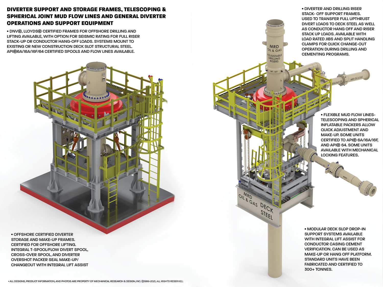
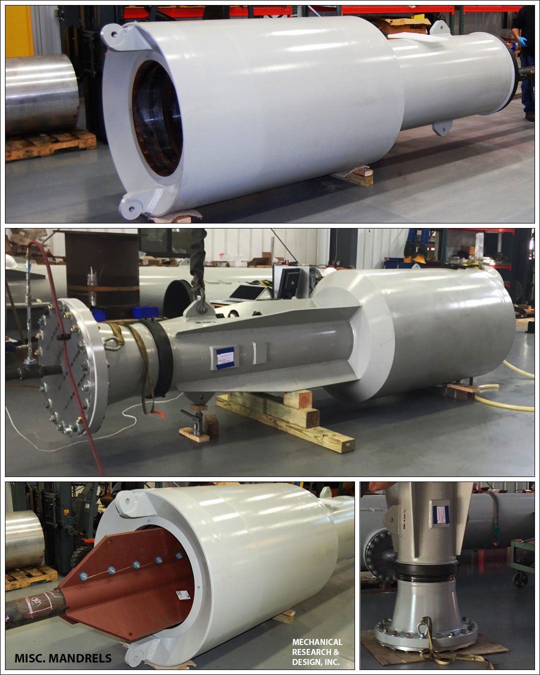
By utilizing our time-tested SEALFAST® inflatable and mechanical seals and packers, we are able to offer many flexible and configurable drilling stack solutions. Our products allow users to adjust for the height, angular alignment, and eccentricities in the drilling stack with unparalleled speed and efficiency. Our, fixed, telescoping, and spherical adjustment riser and mud flow line systems can be designed to accommodate down hole pressures from 5-2000 psig pressure ratings, with process mud temperatures of up to 300° F. Our active sealing technology continues to provide optimal sealing on mandrels and reducing faces, even if they corrode and wear over time, leading to lower maintenance costs
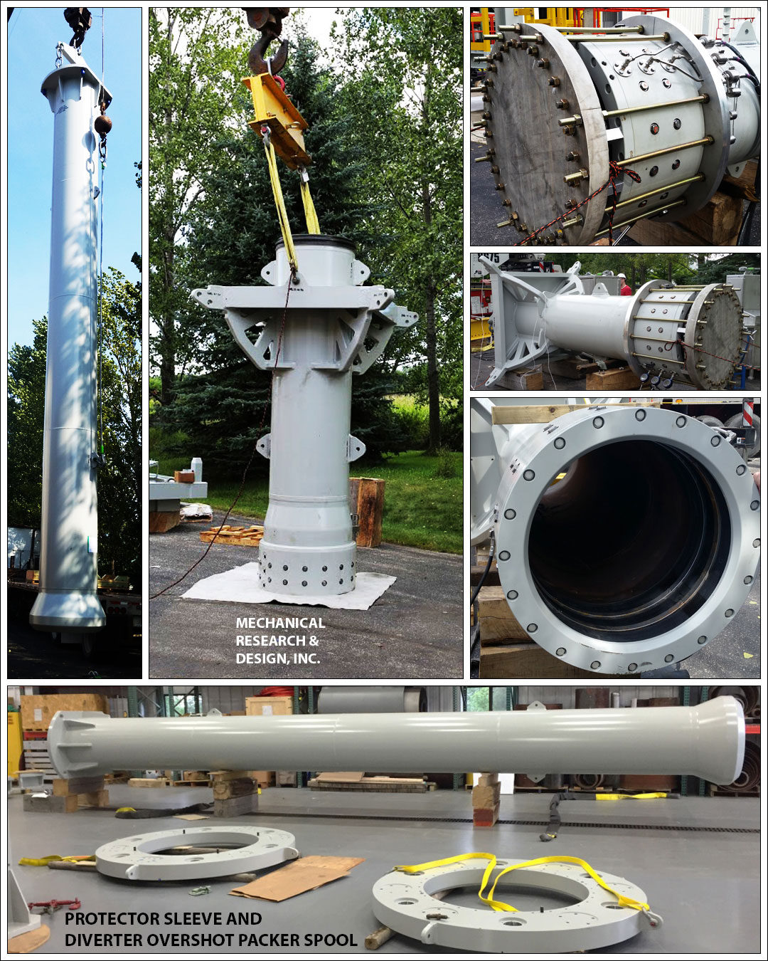
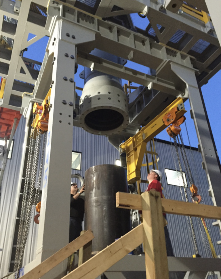
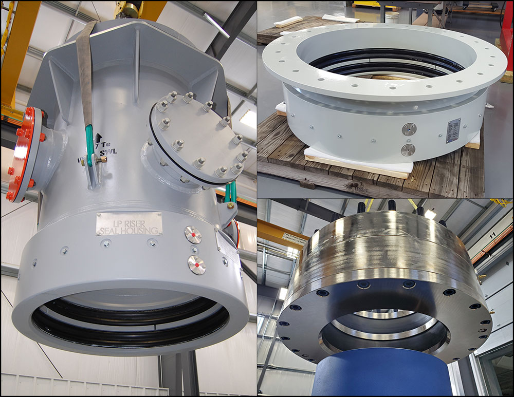
Mechanical Research & Design, Inc. designs and manufactures an assortment of fully certified Diverter and BOP support, restraint, lift, and storage equipment. Most units come certified for offshore portable equipment lifting and can include rated tie-down to deck structural steel for divert and upthrust events. Units can be adapted for integral nozzle load restraint for mud flow lines and safety rated work platforms. These frames are also used as make-up and load-rated hang-off platforms for surface drilling stacks.

• Design pressure ratings vary from 10 PSIG for some bell nipple overshot seal housings, to 2000 PSIG for higher pressure-rated diverter overshot packers.
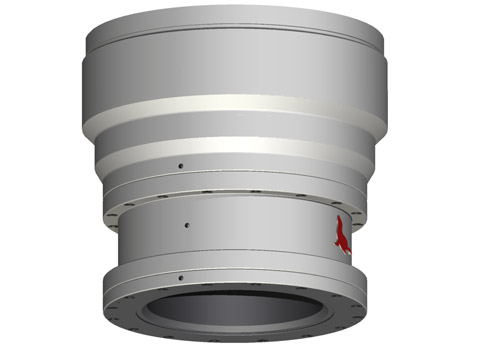
These housings can be mounted under the drill floor or to under-deck structural beams, can integrate a full mud pan, as well as other process and flow lines necessary for managing mud elevations and quality during returns. These units are also ideal for use as weld or bolt-on adjustable low-pressure riser seal housings and diverter overshot seal housings. They allow rapid height adjustment during diverter change-out
• Bell Nipple Overshot Seal Housings: General drilling mud collection and containment housings with integral mud pan; bleed, fill, trip, flow, and swarf lines/nozzles available upon request.
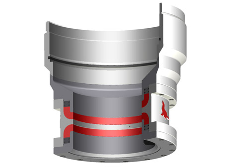
• Diverter Overshot Packer Seal Housings: quick and easy installation and actuation for high-pressure applications – can have integral flow lines to act as a t-spool for diverter stacks.
• Telescoping LP Riser Seal Housings: Best for use with telescoping low-pressure riser systems that require flexible height adjustment and large angular make-up requirements. Often referred to as telescoping riser seal housings or packer seal housings.
These dynamic seal housings are often found on floating production oil rigs, barges, and on drillships. They are commonly paired up with our inflatable spherical packers on KFDS diverter systems or as conductor unions, allowing for the drilling stack to accommodate vertical displacement from standard wave and tidal action, as well as ocean swells. These units come with low-friction mandrels and specially formulated “wear rings” for maximum life.
Often used as an alternative to reducing mandrel spools in bell nipple systems, our SEALFAST® Inflatable and Mechanical drop-in reducers give clients another way to manage various riser and conductor sizes needed for the multiple diverters and BOP stacks needed in some drilling programs. These units are a flexible solution to quickly reduce conductor, and riser sizes while maintaining full drill-through capability. These units can be designed for full hang-off and nozzle loads for the drill stack and can be paired with a mud box or housing that interfaces to the rig floor or underfloor structure.
Available in a wide array of sizes and pressures, our housings can be used laterally, vertically, or on inclines. These units come with and without integral mechanical restraint for full nozzle load requirements. Our new, cutting edge, inflatable and spherical seal housing packers allow for the ultimate flexibility for your mud transport, drill through, or flow line requirements.
Oct242016OILWELL SUPPLIES :(OLD & USED) (SERIAL /PART NO : 119435) 11-1/4 OD FS OVERSHOT EXTENSION - 49 LUnited StatesNhava Sheva SeaUNT1236,708236,708
Oct242016OILWELL SUPPLIES : (OLD & USED) (SERIAL /PART NO : 302008) 11-1/4 OD FS OVERSHOT EXTENSION - 5 FT LUnited StatesNhava Sheva SeaUNT1236,708236,708
Aug192016150-463-A-003 4-5/8 O.D. LOGAN SERIES 150 OVERSHOT,TYPE FS, LESS INTERNAL PARTS,AND FURNISHED WITH 2-7/8 REGULAR BOXUnited StatesBombay Air CargoNOS1109,697109,697
A Diverter Control System can be a freestanding skid, it is designed to prevent the Diverter from shutting in the well. The EFC Group Diverter Control System does so by opening vent lines and closing mud system valves (if applicable) prior to closing the Diverter annular sealing device.

D eep well programs on the Arabian peninsula present unique challenges during the initial phase of drilling operations.Shallow gas pockets may be encountered that require managedwell bore control that is not currently available on existing land rigs.Utilizing feedback from the Saudi Arabian Oil Company (SaudiAramco), Dril-Quip, Inc. has developed the Arabian DiverterSystem (ADS) to address these challenges.The ADS (patent pending) is a portable diverter installed on theconductor and establishes a pressure-tight seal to enable controlleddiversion of any gas pockets that might be encountered. This divert-er system integrates three elements – the diverter housing, packingelements and an overshot spool-type connector – into a unitizedprotection device. The ADS incorporates safe, reliable field-proventechnology and performance features into a 500-psi-rated workingpressure design.Elastomer packers in the diverter close and seal around pipesuspended through the rig’s rotary table, isolating the rig floor fromfluids and gases flowing from the well bore. Large outlets locatedbelow the packers control and divert the flow to a designated area.Hydraulic controls for the diverter system are incorporated into therig’s BOP control system. Valves with hydraulic actuators aremounted on each of the diverter outlet lines to control the move-ment of fluids and gases through the system.The handling and test tools provided facilitate testing, operationand maintenance of the system.
FEATURES• Large-bore diverter accommodates 36" drift• A range of split insert packers provides well bore protection during both drilling and casing operations• Split packer design also facilitates running selected packer elements through a 37-1/2" rotary table• Split insert packer design simplifies installation via weight-set, lock-ring style auto-locking components; no hydraulics required• Overshot radial bolt connector features quick, easy make-up using standard impact wrenches• Overshot connector packer seal is hydraulically energized for reliable control of the well bore fluids• Engineered, designed and operated in accordance with applicable API industry standards• Adaptable to most land drilling rigs• Complete ADS diverter and valve system available from single source (Dril-Quip)
Packer Lockdown Ring Packer Load Ring Main Packer Assembly Main Packer Operation Port Main Body
10" Split Packer 18" Split Packer 27-1/2" Split Insert Packer 32-1/2" Solid Insert Packer Diverter Housing Retrieving Rod Assembly Handling Tool 10" Release Ring 18" Release Ring 27-1/2" Release Ring Tool Joint Pin Diverter Test Tool Diverter system valves not shown in illustration.
Main PackerThe Main Packer is housed in the main body of the diverter, andconsists of a tubular elastomer seal with metal rings molded oneach end. The one-piece packer is retained in the main body ofthe diverter by the packer lockdown, retaining and load ring.The Main Packer functions the insert packers when the diverteris closed. Hydraulic pressure deflects the packer toward the bore,which in turn deflects each of the insert packers installed. TheMain Packer is only removed during maintenance operations. 10" Split Insert PackerSolid Packers and Split Insert PackersThe Solid and Split Insert Packers land in the main body ofthe diverter and are designed to close and seal around variouspipe sizes. The packers consist of a tubular elastomer seal withmetal rings molded on each end. The Split Insert Packers aresplit in half so that they can be installed or retrieved whilepipe is suspended through the rotary table. A spring-loadedlockdown ring is bolted to the top of the packer and retains it inthe previously installed larger packer. Tapped holes in the topof the lockdown ring permit the swivel insert retrieving rodsto release the lockdown ring and recover the packer assemblywhen necessary. Each Split Insert Packer has two alignment slotslocated at the top of the packer to orient the packer assemblysuch that the split between the two halves is offset 90° from the 18" Split Insert Packersplit between the two halves of the previous size. All packers arerated to 500 psi.10" Split Insert PackerThe 10" Split Insert Packer incorporates J-slots on the ID tointerface with the Packer Handling Tool. The packer is operatedwith 925 psi and has a minimum closing diameter of 4-1/2".18" Split Insert PackerThe 18" Split Insert Packer lands in the 27-1/2" Solid Packerand is normally run with the 10" Split Insert Packer. The packeris operated with 850 psi and has a minimum closing diameter 27-1/2" Split Insert Packerof 9-5/8".27-1/2" Split PackerThe 27-1/2" Split Insert Packer lands in the main body of thediverter. It is operated with 750 psi and has a minimum closingdiameter of 26".32-1/2" Solid Insert PackerThe 32-1/2" Solid Insert Packer lands in the main body of thediverter housing. It is operated with 750 psi and has a minimumclosing diameter of 28". 32-1/2" Solid Insert Packer
4Operations Easy, simple Diverter Housing installation Test the Overshot and Diverter Packers The integral Overshot Packer is an adapter The integral Overshot Packer and Split spool that stabs over and provides a Insert Packers are tested with the Packer molded elastomer seal around the field-cut Handling and Diverter Test Tool. 36" conductor casing. A field-welded ring on the conductor OD provides a shoulder for the overshot spool radial bolt-type connector to contain any end-load forces in the event of a shallow gas encounter.
Step 1 Step 2 • Install conductor casing • Test system components with Packer • Weld ring on upper section of casing Handling and Test Tool • Install ADS Diverter System • Retrieve Test Tool • Make up Radial Bolt Overshot Connector • Energize Overshot Packer element
5Reliable managed bore protection Reliable managed annulus duringduring drilling operations casing installationThe Split Insert Packers can be installed The Split Insert Packers are retrievedassembled together with the Packer and the 32-1/2" Solid Packer isHandling Tool or individually with the installed to provide protection duringRunning and Retrieving Rod Assembly. surface casing installation.Hydraulic pressure applied to the MainPacker element functions the InsertPackers closed as required during drill-ing operations.
Step 3 Step 4 • Run drill bit • Run surface casing and cement • Reinstall Packer assembly • Nipple down ADS Diverter System • Drill out for surface casing • Nipple up BOP stack • Retrieve bit and bottom hole assembly
Petroleum and natural gas industries — Drilling and productionequipment — Shallow gas diverter equipmentIndustries du pétrole et du gaz naturel — Équipements de forage et de production — Équipement déflecteurpour gaz de surfaceOGP Draft 113354
Foreword..............................................................................................................................................................v Introduction ........................................................................................................................................................vi 1 Scope ......................................................................................................................................................1 2 Normative references ............................................................................................................................1 3 Terms and definitions ...........................................................................................................................1 4 Diverter system equipment...................................................................................................................7 4.1 General purpose ....................................................................................................................................7 4.2 Findings of blowout reports .................................................................................................................7 4.3 Applications of diverter systems .........................................................................................................8 4.4 Design considerations — Land rigs and bottom-supported marine structures .............................8 4.4.1 General....................................................................................................................................................8 4.4.2 Types of annular sealing devices in use .............................................................................................8 4.4.3 Vent outlets ..........................................................................................................................................12 4.4.4 Diverter valves .....................................................................................................................................14 4.4.5 Diverter piping .....................................................................................................................................15 4.4.6 The control system ..............................................................................................................................18 4.4.7 Kill-line facility .....................................................................................................................................18 4.4.8 Additional functions for the diverter system ....................................................................................18 4.5 Design considerations — Floating rigs .............................................................................................18 4.5.1 General..................................................................................................................................................18 4.5.2 Annular sealing devices in use ..........................................................................................................19 4.5.3 Auxiliary diverter system equipment for riser drilling .....................................................................21 4.5.4 Diverter outlets and valves .................................................................................................................23 4.5.5 Diverter piping .....................................................................................................................................23 4.5.6 Control system .....................................................................................................................................24 5 Floating rigs — Specific aspects .......................................................................................................24 5.1 Use of the marine riser ........................................................................................................................24 5.2 Additional functions of the diverter system .....................................................................................27 5.3 Comparison of types of floating support ..........................................................................................27 5.3.1 Moored drill ships ................................................................................................................................27 5.3.2 DP drill-ships ........................................................................................................................................28 5.3.3 Semi-submersibles ..............................................................................................................................28 5.3.4 Conclusion ...........................................................................................................................................28 6 Preparation for shallow gas operations ............................................................................................30 6.1 Call for tender ......................................................................................................................................30 6.2 Important issues ..................................................................................................................................30 6.3 Pre-spud checks ..................................................................................................................................31 6.3.1 Diesel engines and electrical equipment ..........................................................................................31 6.3.2 Kick and loss detection.......................................................................................................................31 6.3.3 Offshore rescue ...................................................................................................................................31 6.3.4 Offshore cooling recommendations ..................................................................................................31 6.3.5 Offshore emergency-release requirements ......................................................................................31 6.3.6 Rig safety equipment ..........................................................................................................................32 6.3.7 Safety precautions ...............................................................................................................................32 6.3.8 Diverter system ....................................................................................................................................32 6.4 Pre-spud meetings ..............................................................................................................................33 6.5 Pre-spud drills ......................................................................................................................................34 6.6 Preparing the response to a shallow-gas flow .................................................................................34 6.6.1 General..................................................................................................................................................34 6.6.2 Reminders ............................................................................................................................................35
6.6.3 Basic well-control aspects ................................................................................................................. 357 Diverter system maintenance ............................................................................................................ 38 7.1 General ................................................................................................................................................. 38 7.2 Certification and recertification ......................................................................................................... 38 7.3 Diverter system piping ........................................................................................................................ 38 7.4 Manufacturer documentation ............................................................................................................. 39 Bibliography ...................................................................................................................................................... 40
Many past shallow-gas kicks turned into uncontrolled blowouts due to the failure of former diverter systems installed several decades ago. Failure is seen as a result of the system"s complexity, its lack of functional reliability and its inability to cope with the severe dynamic loads,
1 ScopeThis International Standard specifies requirements for the selection of the diverter equipment for rigs used todrill shallow-gas-bearing formations. It covers both onshore and offshore drilling operations, and considersalso the auxiliary equipment associated with floating rigs.
3.11control functioncontrol system circuit (hydraulic, pneumatic, electrical, mechanical, or a combination thereof) used to operatethe position selection of a diverter unit, BOP, valve or regulator
3.13diverterdevice attached to the wellhead or marine riser to close the vertical access and to direct any flow into a set ofvent lines and away from the drilling unit
3.18diverter systemassemblage, comprising an annular sealing device, flow control means, vent system components and controlsystem, which facilitates closure of the upward flow path of the well fluid and opening of the vent to theatmosphere
3.54subsea diverterseabed diverterset-up of equipment attached to the bottom of the marine riser and connected to the 762 mm (30 in) subseawellhead housing, designed to close the well in case of shallow-gas influx and to direct it through two subsealateral vent outlets
3.58telescopic joint packertorus-shaped, hydraulically, pneumatically or mechanically actuated, resilient element between the inner andouter barrels of the telescopic joint which serves to retain drilling fluid inside the marine riser
The diverter system is designed to permit the drilling crew to blow down shallow-gas accumulations downwindof the rig. Until a sufficient casing length has been set to allow a well to be shut-in during a kick, the divertersystem is the only line of defence, and is only expected to contain the hazard temporarily, although as long aspossible.
The diverter system is not intended to be a well-control device. It simply allows the flow to be diverted in asafe manner in order to allow enough time to attempt regaining primary control of the well and, should thelatter fail, enough time for proper evacuation of the drilling crew or for proper move-off of the drilling unit fromthe location (floating rigs), until the flow stops due to gas accumulation blow-down, hole bridging, holecollapse, etc.
Blowout inquiries have concluded that the original designs underestimated the fact that shallow-gas blowoutsproduce huge amounts of gas, together with abrasive solids, flowing at very high speed, producing severedynamic loads, and eroding and destroying many parts of the existing diverter systems.
Statistics obtained in the 1990s in Norway have shown that 54 % of shallow-gas blowouts caused severedamage or total loss of the drilling structure and support, due to the failure of the diverter system.Unfortunately, many lives were lost during those dramatic events.
It is therefore of paramount importance to select suitable equipment able to function in a reliable and safemanner, i.e. able to operate whenever required under the worst possible conditions. Diverter equipment shallalso be able to cope with the prevailing dynamic loads and associated effects.
In the insert-type diverter assembly, the insert packing is latched in place into a diverter assembly, which inturn is locked inside the support housing. This housing provides two outlets, one for the mud returns to flowtowards the shakers, one for the diverted fluids to flow out through the vent line(s). The insert is removed priorto pulling or running the bottom-hole assembly (see Figure 1).
This set-up requires a conventional bag-type preventer and a drilling spool (or diverter spool) which aredirectly located on top of the first casing (conductor pipe, drive pipe). This set-up is therefore below the rotarytable and below the flow-line, unlike the insert-type diverter assembly (see Figure 2).
Key1 Bell nipple 6 Vent line2 Flow line 7 Diverter spool3 Fill-up line 8 Hydraulically operated full opening valve4 Annular packing element 9 Drive / Conductor pipe5 Standard bag-type preventer
insert-type packer usually closes fast (a few seconds), while the operation of the vent and flow- line valves takes much longer (> 40 s), hence imposing a sequencing system to prevent closure of the packer prior to proper operation of the valves;
The standard hook-up option eliminates the need for a flow-line valve, as the flow-line is located at the level ofthe bell nipple, well above the diverter set-up.
The use of an overshot packer, required for length adjustment below the diverter system, is also eliminated,hence removing a potential leak point at pack-off level. Conversely, this adjustment joint and its packer can beused without risk above the bag preventer, as it will not experience any gas flow pressure.
Another safe alternative is to use an integral diverter assembly, which integrates the diverter spool and theannular packing into a single piece of equipment.
In this system the motion of the annular piston is used, in one stroke, to first open the vent lines and then stopthe upward flow. The flow-line is located at the level of the bell-nipple, well above the integral diverterassembly, hence eliminating the need for a specific flow-line valve (see Figures 3 and 4).
Several types of valve are commonly associated with diverter systems: gate valves, ball valves, switchablethree-way target valves, knife valves, valves integral to the diverter unit and sometimes burst disks.
For insert-type diverter systems requiring actuation of valves on both shaker and vent lines, an interlocksystem shall prevent the diverter from closing before the valves are in the correct position (i.e. shaker valveclosed, vent-line valve open). This is of paramount importance with these systems, where the response timeof the insert packer is much lower than that of the shaker and vent-line valves [usually less than 10 s to closeon a 127 mm (5 in) drill pipe].
Actuators fitted to a diverter valve shall be sized to open the valve at least with the rated working pressure(WP) of the diverter system applied across the valve.
The safest and most reliable option is the integral diverter system (see Figures 3 and 4) in which the physicalneed for valves is eliminated. In such a system, the shaker and fill-up lines are located far above the divertersystem within the rig sub-structures, and do not require any shut-off valves.
Diverter piping shall consequently be sized and its layout designed such that the anticipated back-pressure,calculated with realistic gas flow rates, do not exceed the rated working pressure of the diverter system, donot exceed the design pressure of other equipment, and do not place undue pressure on the wellbore.
At the rig site location, the diverter vent-lines shall extend a sufficient distance in the most appropriatedirection from the rig to permit safe venting of diverted well fluids.
Consequently, the minimum required nominal internal diameter (ID) of diverter outlets and vent-lines shall be355,6 mm (14 in). The piping wall thickness shall not be less than 19,05 mm (0,75 in).
The diverter control system shall be designed and sized in accordance with API 16D:2005, Section 5.5. It shallcontain the minimum of functions. Preferably, a one-button or lever-activated function shall operate the entirediverter system.
A 38,1 mm (1½ in) hydraulic operating line should be used for diverter systems with a 1½ in NPT closingchamber port size. The hydraulic line for the opening chamber port may be 25,4 mm (1 in).
Many shallow-gas blowout reports have mentioned failures of the pneumatic control system used to operatediverter valves (e.g. failure to work as required when valves stems are blocked with solids). A pneumaticcontrol system shall therefore be avoided on rigs, if possible.
Each diverter system should incorporate a kill-line facility (including a check valve) to allow pressure-testing ofthe annular packing element closed on open hole, with no pipe in hole. This facility can also be used toperiodically flush the system clean.
Another advantage of a kill-line facility is to pump water through the diverter system during a gas-flow divertingoperation, in order to wet the gas and accordingly reduce the fire risk.
The use of a diverter system (alone or combined with a BOP set-up) should be considered on multi-wellplatforms, due to potential hazards such as collision with adjacent wells or surface-gas accumulations due topoorly cemented casings.
Though many parts of the diverter system are identical to those used on land rigs and bottom-supportedmarine structures, others are specific to floating units and are reviewed hereafter.
When drilling shallow-gas-bearing formations with a riser, two types of sealing device are used: the surfaceinsert-type diverter assembly and the subsea diverter.
By design, this system is basically similar to the system used on land rigs and bottom-supported marinestructures. The diverter support housing is permanently fixed to the drill-floor substructure below the rotarytable at the upper end of the marine riser system, and provides outlets for the shakers and for ventingpurposes. The diverter assembly is locked down inside the housing, and the insert packer is locked inside thelatter.
For floating supports, the possibilities to improve the surface vent-lines network and routing being substantiallyreduced, the subsea diverter system is a safer alternative. The basic set-up includes, from top to bottom: aflex joint, an annular BOP (or a shear ram unit), a diverter spool and a riser hydraulic connector (seeFigure 6).
If the subsea diverter option is selected, it is recommended to hook up a riser booster line above the upperclosing unit (bag or shear ram), to eliminate any gas which has entered the riser before complete well shut-off.An additional diverter system (e.g. the basic insert-type assembly) is required at surface to deal with this gasinflux (see also 4.5.2.3 and 5.2).
Prior to choosing this option, it is important to look carefully at the water depth and the type of support vesselwhich has been selected. Even after its transit through the water column, gas still represents a potentialexplosion and fire hazard, mainly as it concentrates in the moon-pool area. With gas being vented at seabedlevel and percolating up to surface, the subsea diverter is probably not the best choice with a drill-ship inshallow water depths.
Key Key1 539,7 mm (21 1/4’’) Flex Joint 1 539,7 mm (21 1/4’’) Flex Joint2 539,7 mm (21 1/4’’) Annular BOP 2 539,7 mm (21 1/4’’) Annular BOP3 539,7 mm (21 1/4’’) Diverter spool w/ integral valving 3 539,7 mm (21 1/4’’) Shear ram and 304,8 mm (12’’) outlets 4 539,7 mm (21 1/4’’) Diverter spool4 Guide structure 5 Outlet nozzle5 762mm (30’’) Hydraulic connector 6 762 mm (30’’) Hydraulic connector
NOTE The diverter is shown here in the drilling mode. When the diverter closes in case of gas influx, the piston movesupward, opening the flow path to the vent line while closing the flow path to the flow line.
Should surface diverting be considered as too hazardous (in particular if the integral diverter system is notavailable), the requirement for safe operation is to use the subsea diverter. Its use depends however on thewater depth at the drilling location, the virulence of reported local shallow-gas events, the type of supportvessel contemplated and the competence of the chartered drilling contractor.
The insert-type diverter system should only be used in conjunction with a subsea diverter or with a BOP stack,to circulate and vent out any gas trapped in the riser (see 5.2).
The same comments for land rigs and bottom-supported marine structures given in 4.4.3 and 4.4.4 apply tovent outlets and diverter valves for floating rigs.
On floating rigs (as for land rigs and bottom-supported marine structures), since the size and number of vent-lines have a great influence on surface and downhole hazards, two properly sized vent-lines shall be used.The minimum nominal ID of diverter outlets and vent-lines shall be 355,6 mm (14 in).
Key1 Flow selector always open2 Diverter with integral valve functions3 To Shale shaker4 To Vent lines5 To Starboard vent line6 To Port vent line
The diverter control system shall be designed and sized according to API 16D:2005, Section 5.5. Pneumaticcontrol systems shall be avoided on rigs working in shallow-gas-prone areas.
Each operating company has its own drilling policy with respect to using (or not) the marine riser while drillingshallow-gas-prone formations. The general mistrust of existing diverter systems on most floating rigs has ledsome operators to adopt a riserless approach. The following comments can be made.
Whatever the pros and cons of riser use, a preliminary careful and thorough review of the reliability andcapacity of the rig diverter system (see 4.5.2) and of the reliability and capacity of the emergency-releasesystem of the floating-support mooring lines can provide decisive criteria to assist in selecting the beststrategy.
Gas can inadvertently enter the riser when the BOP is shut-in on a kick. Gas can also enter the riser if the rams leak after the BOP is closed. Using the diverter system, the gas in the riser can be safely removed and diverted overboard,
After a kick circulation is completed, some compressed trapped gas can remain between the closed BOP and the choke-line connection. This gas will tend to migrate into the riser when the BOP is re-opened. Using the diverter system, this gas can also be safely removed and diverted overboard.
a competent drilling crew, having past experience in shallow-gas drilling, purposely trained and familiar with the diverter equipment and its proper testing, maintenance, and operation;
Prior to drilling a shallow-gas formation, all the diverter system components shall be inspected and tested toascertain proper installation and function. As a minimum, the following tasks shall be carried out.
Ensure that any fill-up line which can be exposed to the gas flow is protected with a check valve; this line and check valve shall have a WP equivalent to that of the diverter system.
d) Simulate loss of rig air supply to the diverter control system and determine effects, if any, on the diverter system, valves, and back-up systems.
On a routine basis, when in primary diverter service (no BOP installed), function tests should be performeddaily using the driller’s panel to verify that functions are operable. Fluid should be regularly pumped througheach diverter line during drilling operations to ensure that they are clear of obstructions at all times.
review all preliminary checks related to, among others, the diverter system, kick detection equipment, kill mud volumes, emergency power supply, safety, rescue and emergency equipment, emergency communication systems, mooring equipment if applicable, etc.;
All concerned personnel should therefore be familiar with the diverter system components and installation,and should be capable of reacting quickly and efficiently to potential situations requiring use of the diverter.
Any defect or problem with equipment or personnel identified during any of these pre-spud drills should beimmediately reported and dealt with before drilling is permitted to start. Thereafter, drills should be conductedat appropriate intervals to ensure personnel are capable of quickly and competently reacting to situationsrequiring use of the diverter.
If practically feasible, a tentative well kill should be attempted immediately with heavy kill mud and themaximum pumping rate available, after the diverter system has been activated, to try to stop the gas flowdownhole, prior to complete well unloading.
A schedule for routine inspection and maintenance of diverter systems equipment should be prepared andmaintained by the rig operating personnel. Specific guidelines for each diverter component or sub-systemshould be based on installation, operation and maintenance manuals provided by the equipmentmanufacturer.
During diverter function tests, observe all components of the diverter system including the diverter, valves, valve actuators, piping, and control panel to verify that there are no leaks in the system. If a leak is discovered, it should be repaired immediately.
All diverter equipment shall be maintained with original equipment manufacturer’s (OEM) genuine or approved spares and shall be operated and tested in accordance with that manufacturer"s recommended procedures. Major repairs, overhaul on and recertification of diverter equipment shall be performed either by the OEM or an alternative provider, but then only when approved by the OEM.
A visual inspection, a body-pressure test and a full-function test shall be carried out once a year on a diverter test stump at surface, in accordance with the manufacturer"s specification for such a test and witnessed by a certified third party. Results of the inspections and tests, including follow-up, shall be documented, providing full traceability and be part of the formal service history.
At least every five years, the diverter system components shall be inspected for repair or remanufacturing by the OEM or OEM-approved service provider. Upon completion of the inspection, the OEM shall provide a Certificate of Conformance (COC).
The wall thickness on all undesirable turns and bends (if any) in the diverter system piping should be checkedat least annually and after each use of the system to divert a well kick. Erosion of metal from the turns andbends can be severe if sustained flows of gas-associated solids are diverted through the system.
Installation, operation and maintenance manuals furnished by the manufacturers of the various components ofthe diverter system should be readily available for training, reference, and use by maintenance personnel.
The present invention is directed, in general, to well drilling and completion and more specifically an improved diverter, diverter retrieving and running tool and methods for running and retrieving a diverter.
Another prior art completion technique calls for the drilling of one or more open hole lateral wellbores from a main wellbore. A special casing having a number of inflatable open-hole packers and perforations between the inflatable packers is placed in the main wellbore. The inflatable packers serve to separate the lateral wellbores hydraulically from one another. This technique therefore offers a degree of isolation, in that an entire lateral can be sealed off from the rest. However, portions of a lateral cannot be sealed off. Further, there is neither connectivity nor access. Finally, the lateral wellbores are left open-hole. Therefore, if a lateral wellbore collapses or becomes clogged, production from that wellbore is compromised.
The problem of lateral wellbore (and particularly multilateral wellbore) completion has been recognized for many years as reflected in the patent literature, For example, U.S. Pat. No. 4,807,704 discloses a system for completing multiple lateral wellbores using a dual packer and a deflective guide member. U.S. Pat. No. 2,797,893 discloses a method for completing lateral wells using a flexible liner and deflecting tool. U.S. Pat. No. 2,397,070 similarly describes lateral wellbore completion using flexible casing together with a closure shield for closing off the lateral. In U.S. Pat. No. 2,858,107, a removable whipstock assembly provides a means for locating (e.g., accessing) a lateral subsequent to completion thereof. U.S. Pat. No. 3,330,349 discloses a mandrel for guiding and completing multiple horizontal wells. U.S. Pat. Nos. 4,396,075; 4,415,205; 4,444,276 and 4,573,541 all relate generally to methods and devices for multilateral completions using a template or tube guide head. Other patents of general interest in the field of horizontal well completion include U.S. Pat. Nos. 2,452,920 and 4,402,551.
Over time, it may become necessary to reenter a selected one of the lateral boreholes for rework or other purposes. To this end, the prior art has provided diverters that may be placed within and removed from the main borehole as desired. However, some significant disadvantages are associated with such prior art diverters.
First, the topography of the main well flow conductor, particularly at the junction between the main and lateral boreholes, is often unknown and subject to variation. The tools designed to enter the lateral well flow conductor may have a relatively large diameter, that is, just slightly smaller than that of the main well flow conductor so that there are close tolerances between the two. Thus, there is little room for movement of the tool within the main well flow conductor in the event that there is a defect or protrusion above or at the junction that serves to decrease the effective diameter of the main well flow conductor. In this case, the tool may become lodged in the well bore at the obstruction. Such defects arise, for instance, when the window at the junction of the main and lateral boreholes is malformed. This may result in tools not being able to get through the window to the lateral well flow conductor. Prior art diverters are rigid; thus, such diverters are unable to adjust dynamically or compensate for deviations or malformations.
Second, retrieving such prior art diverters is difficult. Prior art retrieval was generally by one of two methods. The first employs an overshot to engage an outer diameter of the diverter. Unfortunately, the diverter may not be centralized, making it difficult for the overshot to fit around the diverter. The second employs a retriever designed to engage a specific coupling point on the face of the diverter. Unfortunately, such retrieving tools must first be oriented with respect to the diverter, else they fail to engage and retrieve. This is unnecessarily complicated and may require multiple trips should the orientation of the retrieving tool be incorrect.
Therefore, there is a need in the art for an improved diverter, retrieval tool and methods for diverting and retrieving that take into account possible fluctuations in well flow conductor diameter and that simplify and render diverter retrieval more reliable than in the prior art.
To address the above-discussed deficiencies of the prior art, it is a primary object of the present invention to provide a diverter that has a compliant diverter surface thereon, allowing the diverter to adjust or compensate for deviations in the main borehole, junction or lateral borehole that would pose an obstacle to passage of the tool if the diverter surface were not compliant.
In the attainment of the primary object, the present invention provides a diverter for a subterranean well, a diverter retrieving tool and methods of diverting objects traversing the well and retrieving the diverter. In a first aspect, the present invention provides a diverter comprising: (1) a body having a lower portion adapted to be coupled to a diverter anchoring structure and an upper portion having a slanted diverting surface, the diverter adapted to be placed within a main borehole of the subterranean well at a predetermined location and orientation proximate a junction of a lateral borehole with the main borehole, the slanted diverting surface adapted to redirect an object having a particular diameter and coming into contact with the diverter into the lateral borehole and (2) a compliant spring member associated with the slanted diverter surface, the spring member resiliently retractable toward the slanted diverter surface to allow the object to traverse the junction and enter the lateral borehole, the diverter therefore dynamically adjustable to compensate for an insufficient minimum diameter of a selectable one of the main borehole, junction and lateral borehole.
Thus, it can be seen that the diverter employs a spring member to urge against any object (such as a tool) that may come into contact with the diverter. If the diameters of the main borehole, junction or lateral boreholes are sufficient to allow the object to pass, the spring member need not comply. However, if the diameters are constricted, perhaps owing to a defect occurring during formation of the junction, the spring member retracts to create the extra diameter needed for the tool to pass the constriction.
In a preferred embodiment of the present invention, the body is composed of a composite material. It is a further, lesser object of the present invention to employ composite materials to advantage wherever possible. Those of skill in the art are familiar with the strength and weight advantages of composite structures. The present invention, in this preferred embodiment, takes advantage of these advantages. It should be understood, however, that a diverter composed of a metallic or a non-metallic, non-composite material is also within the scope of the present invention.
In a preferred embodiment of the present invention, the diverter further comprises a second compliant spring member associated with the slanted diverter surface. The compliant spring members cooperate to allow the object to traverse the junction and enter the lateral borehole.
Thus, the present invention contemplates multiple compliant spring members. As will be described, the spring members may be in a longitudinally or laterally spaced-apart configuration. In the illustrated embodiment, there are three spring members, arranged at two longitudinally spaced-apart locations. At the upper location, two springs are paired. At the lower location, there is a single spring. In a manner to be described, this arrangement has the further advantage of allowing the retrieving tool to engage the diverter.
In a preferred embodiment of the present invention, the body has a central longitudinal shaft and a dilated opening to the central longitudinal shaft on the slanted diverter surface. The dilated opening is adapted to receive a retrieving tool into the central longitudinal shaft. The retrieving tool engages the body within the central longitudinal shaft to allow the retrieving tool to exert a retrieving force on the body.
Thus, in this preferred embodiment, the diverter is uniquely adapted to receive a centrally-located retriever. This is in contrast to the prior art, wherein a retriever may employ an overshot to engage an outer diameter of the diverter or the retriever, which first requires orientation with respect to the diverter. Once properly oriented, the retriever then engages a coupling point on the face of the diverter.
In a preferred embodiment of the present invention, a segment of the diverter"s upper portion has a diameter less than that of the lower portion thereby allowing an overshot associated with a retrieving tool radially to surround the segment. The present invention, in this embodiment, makes use of an overshot to surround the segment of the diverter. However, as opposed to the prior art, the overshot does not engage the diverter to retrieve the same.
In another preferred embodiment of the present invention, the lower portion of the body has threads to receive the diverter anchoring structure, the threads being shearable upon application of a predetermined separating force to separate the body from the diverter anchoring structure. Thus, if the diverter anchoring structure is irretrievably retained within the main borehole, the diverter may be separated therefrom by stripping the threads.
In another aspect of a preferred embodiment of the present invention, the diverter anchoring structure comprises a locating key for engaging the anchoring structure at the predetermined location within the main borehole. The locating key has a profile adapted to engage a nipple on an inner diameter of the main borehole. Those of skill in the art are familiar with such locating keys and their function.
In yet another aspect of a preferred embodiment of the present invention, the diverter anchoring structure comprises an orienting lug for engaging the anchoring structure at the predetermined orientation within the main borehole. The orienting lug, like the locating key, engages a recess in the inner diameter of the main bore. The recess is oriented, thereby orienting the diverter toward the lateral borehole.
In a preferred embodiment of the present invention, the diverter has an interface associated therewith for receiving an elongated portion of a retrieving tool. The elongated portion has a shearable section to allow the elongated portion to separate from a remainder of the retrieving tool upon application of a predetermined separating force. Thus, should the diverter be stuck within the main borehole, the retrieving tool can be separated therefrom upon application of the predetermined separating force.
In a second aspect, the present invention provides a retrieving tool for a diverter wherein the diverter includes a body having a slanted diverting surface and a central longitudinal shaft associated therewith, the retrieving tool comprising: (1) a housing having a predetermined diameter and adapted to traverse a length of a main well flow conductor and (2) an elongated flexible finger having an interface end coupled to the housing and a distal bulbous end, the housing substantially centralizing the bulbous end with respect to the main well flow conductor, the bulbous end adapted to contact the slanted diverting surface and enter the central longitudinal shaft as the retrieving tool merges with the diverter, the bulbous end adapted to engage the body within the central longitudinal shaft as the retrieving tool is drawn away from the diverter, the elongated flexible finger capable of transmitting a retrieving force to the diverter to displace the diverter longitudinally within the main borehole.
Thus, in this aspect of the present invention, the retrieval tool reaches into the diverter to grasp the diverter from within. This is as opposed to the prior art methods of grasping the diverter from without or grasping the diverter at a prescribed location on the diverter face, therefore requiring that the retrieving tool be pre-oriented.
In this preferred embodiment, the elongated flexible finger is composed of a composite material, wherein the bulbous end is able to deviate from a centerline of the main well flow conductor as the elongated flexible finger flexes. Again, composite structures possess distinct weight and strength advantages that are outside of the scope of the present discussion. In a manner to be illustrated, the bulbous end moves from the centerline as it traverses the slanted diverting surface. Eventually, the bulbous end snaps back toward the centerline when it reaches a dilated opening in the slanted diverting face. This places the bulbous end within the diverter and in position to engage and retrieve the diverter.
In a preferred embodiment of the present invention, the housing has an overshot portion radially surrounding the elongated finger member, the overshot portion substantially centralizing the elongated flexible finger with respect to the main well flow conductor, thereby eliminating a need to radially orient the retrieving tool with respect to the slanted diverting surface. As just described, the slanted diverting face decentralizes the bulbous end of the flexible finger which has at least partially rounded ends. Thus, in effect, the diverter itself "orients" the retrieving tool, although the tool itself never has to be rotated during this "orientation." The overshot portion not only centralizes the flexible finger, but also protects the flexible finger from damage or unintended engagement with the main well flow conductor as the retrieving tool is lowered into place. This can be contrasted to prior retrieving tools having hook like structure that must be specifically oriented for engagement.
In a preferred embodiment of the present invention, the diverter comprises a pair of compliant spring members associated with the slanted diverting face, the bulbous end traversing the slanted diverting surface between the compliant spring members. As will be illustrated, the compliant spring members are placed on either side of a track formed in the slanted diverting surface. The bulbous end rides in the track until it drops into the dilated opening. This interaction is at least partially facilitated by the characteristics of the composite material from which the finger member is constructed. However, it is contemplated that the finger member could be constructed from other suitable material.
In a preferred embodiment of the present invention, the body further has a dilated opening to the central longitudinal shaft on the slanted diverter surface, a diameter of the central longitudinal shaft decreasing to form a receiving pocket proximate the dilated opening, the dilated opening adapted to receive the retrieving tool into the central longitudinal shaft, the retrieving tool entering the pocket and engaging the body to allow the retrieving tool to exert the retrieving force on the body. This is as previously described.
In a preferred embodiment of the present invention, the elongated portion has a shearable section to allow the elongated portion to separate from a remainder of the retrieving tool upon application of a predetermined separating force. Again, should the elongated portion become stuck in the diverter, the separating force can be applied to remove the remainder from the diverter.
In a preferred embodiment of the present invention, the elongated flexible finger is removable from the housing, the housing joinable to the diverter by a shear pin thereby to allow the housing to function as a running tool for the diverter. Thus, the retrieving tool can be configured as a diverter running tool by removing the flexible finger, inserting the diverter into the (now running) tool and coupling the two with the shear pin. When the diverter is set into place, a separating force can be employed to shear the shear pin, thereby freeing the running tool.
FIG. 1 illustrates a side cross-sectional view of the diverter of the present invention showing the compliant spring members and the central longitudinal shaft with the dilated opening therein;
FIG. 1B illustrates a cross-sectional view of FIG. 1 taken along the line 1B--1B showing the upper portion of the diverter face and the concave upper portion of the track in the central longitudinal shaft;
FIG. 1F illustrates a cross-sectional view of FIG. 1 taken along the line 1F--1F showing complete an opening in the central longitudinal shaft and a second spring member in a lower portion of the diverter;
FIG. 1G illustrates a cross-sectional view of FIG. 1 taken along the line 1G--1G showing the opening in the central longitudinal shaft and the lower end of the diverter face in a lower portion of the diverter; and
FIG. 1H illustrates a cross-sectional view of FIG. 1 taken along the line 1H--1H showing the opening in the central longitudinal shaft after which the concave portion of the diverter face has terminated in the lower portion of the diverter;
FIG. 2 illustrates a retrieving tool having a housing with a predetermined dia


 8613371530291