
overshot gate made in china

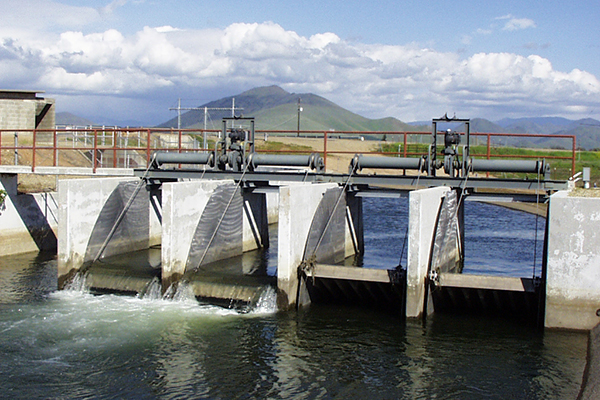
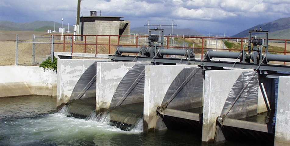
Overshot gates (also known as pivoting weir gates) are used to control upstream water levels. Versatility, efficiency, and safety are the primary reasons the Fresno Overshot Gate is the method of choice for municipal, agricultural, and industrial canal water control.
Auke Water’s parent company Fuda Group have serviced the water industry in China for 20 years constructing large dam gates in their Jiangsu factory. To expand their product line Fuda created Auke Water, a company who would be dedicated to providing intelligent irrigation solutions within China and East Asia. Auke realised that it did not have the technical experience to produce high quality irrigation solutions, although it had sufficient manufacturing experience to produce quality gates.
After licensing the initial gates designs from a well-known international irrigation gate manufacturer ICS worked with the Auke engineers to produce a range ofhigh qualityaluminium gates that are capable of serving all the typical irrigation canal operations. The range of gates includes overshot regulators capable of accurate in channel flow measurement, undershot regulators and metered farm offtakes.
ICS worked with the electrical engineers to develop standard control systems that are installed on the gates to facilitate the automatic operation, telemetry, local user interface, and power supply. The control systems use all commercially available off the shelf hardware and software which is important to ensure the clients can support and maintain their system economically.
ICS worked with Auke to develop two methods of internet connectivity for their automated gate systems. Two systems were developed so Aukeisable to provide their clients with commercial competitive IoT communication systems for both small projects (e.g less than 40 sites) and large projects. Having every site remotely connected to the internet provides Auke and their clients with a massive advantage when it comes to commissioning, supportandmaintenance. Any updates or troubleshooting that the sites require after installation are easily completed by Aukes engineers without the need to travel tosite, which significantly reduces the maintenance cost and reduces downtime.
ICS’s experience with designing and manufacturinghigh qualityaluminium and stainless steel water gates allowed Auke Water to fast track their in-house design and manufacturing capabilities. ICS trained the engineers and factory personnel on the details of quality water gate design including design principals, material selection and manufacturing procedures.
ICS produced a comprehensive training manual and conducted a series of training sessions with Auke’s salesmen and engineers to train the staff on the fundamental and advanced aspects of canal modernisation. The sessions covered a range of topics from canal evaluation, gate selection, control system development and customisation, canal control algorithm specification and commissioning, SCADA development and cloud computing fundamentals. The comprehensive training sessions enabled the Auke staff to better understand theirclient"sneeds and to effectively turn those needs intohigh qualityproject solutions.
I am using a sluice gate with an ogee inline structure. I have never worked directly with an ogee weir and HEC-RAS asks for inputs like "Spillway approach height", and "Design energy head". I am not quite sure what this is in reference too. Is there a post or reference manual somewhere that explains this more in depth?
Chris, we have a model with these sorts of overshot gates, that run the entire length of a dam. We are modeling these gates as initially closed, and as a large hydrograph comes through the gates fail and are fully open. Then during the same hydrograph we are trying to model a breach of the inline structure. However, the results of the "with breach" case match the results of the "no breach" case exactly. It"s as though RAS is treating the breach opening like it"s not there, or that water cannot flow through it. Is this true for RAS, that it does not recognize a breach that is below an overshot gate? I ask because if we take the gate out and just pretend that they were open the whole time so that there is only the inline structure, the resulting hydrograph shows the impact of the breach. Thanks Chris.
Cory- That is intriguing. I"ve never run into that before, but I can see how there might be some unintentional conflict in the code with breaching under a gate. Can you send me your model using the debug report (http://hecrasmodel.blogspot.com/2008/12/hec-ras-debug-report.html) and I"ll see if I can see what is going on? Thanks-cgoodell@westconsultants.com
I was wondering why sometimes different kinds of gates( I mean overflow and underflow gates) is being used in the same check structures. I have seen many checks with five gates with 2 under flow gates on side and 3 overflow in middle. what is the purpose of such a design? Furthermore In time of operation do all gates open together or not?
Mike, honestly I don"t know the typical purposes of such gates. I have seen them used for fish passage, where the multiple outlet options give fish a preference for how they want to pass. Otherwise, not sure…
Hi, I am a relatively new user. I am confused about a simple thing. I want to model a overflow structure with around 15 gate openings. Do I need to draw a solid embankment extending from the starting to the ending of the gates using the weir/embankment option under inline structure before defining the gates? Or do I need to keep opening in the embankment?
I like to model radial gates and sluice gates with broad crested weir. Is it possible to use broad crested weir with radial gates. Even though in the selection dialogue box it is there, I doubt that, as all the explanations related with radial gates are drawn with ogee spillway.
Hi Chris, thanks for pointing out this option! One thing is not clear to my however: How can I control the gate"s Crest Level (as opposed to the Gate Opening Height)? Is the only way to do this by implementing a closed top overflow gate and applying negative opening heights to it so as to keep the gates closed at all times and only allow for flowing over the gate"s top? Or is there an option using an Open Air gate as well? As far as I can tell the Unsteady Data Editor only provides a possibility to enter a timeseries for the Gate Opening Height; not for the Gate Crest Level.
Siebe, with overflow gates, the gate opening value you enter in the unsteady boundary condition is measured from the maximum gate top elevation (gate fully up) to the actual gate top elevation. For example, you set the Height in the overflow gate geometry properties to 4 meters. And the gate invert elevation is 0 meters. If you put in a gate opening height of 1 meter in the unsteady flow boundary condition table, the gate will be open so that the crest of the gate is at elevation 3 meters.
Thanks Chris! It"s rather embarrassing how long it took me to understand the concept :"(. In The Netherlands we simple don"t have any gates that move downwards in order to open up. All of our gates are opened by pulling them up, so it took a little mind bending to understand it.
Since RAS doesn"t have a double door type gate built in, you have to do some sort of workaround. If you can accept a little bit of error during the opening/closing sequence, you could just pick one of the available gates and try to make it work that way. This might be okay if the gate opens/closes relatively quickly. Or, you could develop your own rating curve and model the gate with user-defined curves. The problem with this is that user-defined curves are tailwater independant, and based on your description and photos, that is not the case for your gate. That leaves you with writing rule scripts. It"s sort of complicated, but you could develop rating curve tables for a range of tailwaters, and use rules to pick from the correct table, based on the computed tailwater. That"s probably what I would do if I needed it to be super accurate. Otherwise, I"d probably just go with one of the built-in gates available in RAS.
sir i am not getting that which height is called as invert height/level of gate. radial gate discharge coefficient and trunnion height of gate please help me out
That is a great article. I am facing a problem and interested in your opinion. I have to model a two boarded gate. My problem is that this type of gate allow an adjustable overflow height and can be opened from the bottom in the same time as well, or lower both board to a minimum overflow height, or raise both board to make a huge opening. Is this even possible? i am thinking on putting a normal gate and an overflow gate right on top of each other but not sure program van handle it.
I like your idea for a solution. I think you can put one on top of the other as different gate groups. However, if the program doesn’t like that, you can always put one next to the other. Good luck. Let me know how it goes.
The only issue i encountered so far is with closed top overflow gates i receive a warning about overlapping gates but it can be ignored and works fine. With open air solution there is no warning.

A slab gate valve is a sliding valve in which the closing members are parallel rams. The closing member may be a single shutter or a double shutter with a distracting mechanism therebetween.
The pressing force of the shutter to the valve seat is controlled by the medium pressure acting on the floating gate or the floating valve seat. If it is a double gate slab gate valve, the expansion mechanism seen by the two gates can supplement this pressing force.

WATERMAN TILTING WEIR (OVERSHOT) GATESare an overflow-type gate used to control levels in canals, basins and other agricultural, municipal and industrial applications.
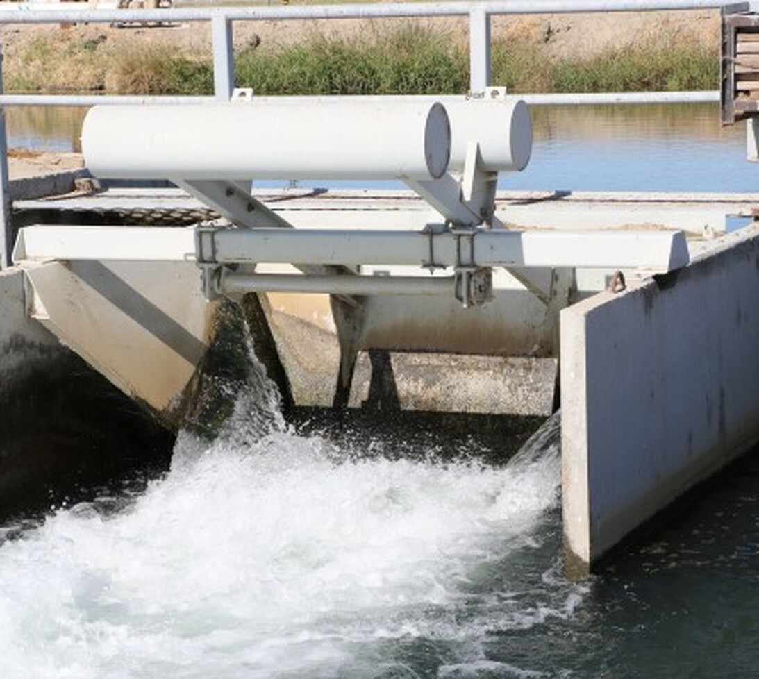
The basic gate design uses a rectangular panel mild steel panel that is mounted to a piano hinge at the forward bottom edge of the gate leaf. This leaf is raised and lowered using a cable drum hoist to control the upstream water level.

One major way to classify watermills is by wheel orientation (vertical or horizontal), one powered by a vertical waterwheel through a gear mechanism, and the other equipped with a horizontal waterwheel without such a mechanism. The former type can be further divided, depending on where the water hits the wheel paddles, into undershot, overshot, breastshot and pitchback (backshot or reverse shot) waterwheel mills. Another way to classify water mills is by an essential trait about their location: tide mills use the movement of the tide; ship mills are water mills onboard (and constituting) a ship.
There are two basic types of watermills, one powered by a vertical-waterwheel via a gear mechanism, and the other equipped with a horizontal-waterwheel without such a mechanism. The former type can be further divided, depending on where the water hits the wheel paddles, into undershot, overshot, breastshot and reverse shot waterwheel mills.
The Greeks invented the two main components of watermills, the waterwheel and toothed gearing, and used, along with the Romans, undershot, overshot and breastshot waterwheel mills.
Typically, water is diverted from a river or impoundment or mill pond to a turbine or water wheel, along a channel or pipe (variously known as a flume, head race, mill race, leat, leet,penstock). The force of the water"s movement drives the blades of a wheel or turbine, which in turn rotates an axle that drives the mill"s other machinery. Water leaving the wheel or turbine is drained through a tail race, but this channel may also be the head race of yet another wheel, turbine or mill. The passage of water is controlled by sluice gates that allow maintenance and some measure of flood control; large mill complexes may have dozens of sluices controlling complicated interconnected races that feed multiple buildings and industrial processes.
Most watermills in Britain and the United States of America had a vertical waterwheel, one of four kinds: undershot, breast-shot, overshot and pitchback wheels. This vertical produced rotary motion around a horizontal axis, which could be used (with cams) to lift hammers in a forge, fulling stocks in a fulling mill and so on.
However, in corn mills rotation about a vertical axis was required to drive its stones. The horizontal rotation was converted into the vertical rotation by means of gearing, which also enabled the runner stones to turn faster than the waterwheel. The usual arrangement in British and American corn mills has been for the waterwheel to turn a horizontal shaft on which is also mounted a large pit wheel. This meshes with the wallower, mounted on a vertical shaft, which turns the (larger) great spur wheel (mounted on the same shaft). This large face wheel, set with pegs, in turn, turned a smaller wheel (such as a lantern gear) known as a stone nut, which was attached to the shaft that drove the runner stone. The number of runner stones that could be turned depended directly upon the supply of water available. As waterwheel technology improved mills became more efficient, and by the 19th century, it was common for the great spur wheel to drive several stone nuts, so that a single water wheel could drive as many as four stones.sluice gate and thus the flow of the water past the main wheel allowed the miller to compensate for seasonal variations in the water supply. Finer speed adjustment was made during the milling process by tentering, that is, adjusting the gap between the stones according to the water flow, the type of grain being milled, and the grade of flour required.
An inherent problem in the overshot mill is that it reverses the rotation of the wheel. If a miller wishes to convert a breastshot mill to an overshot wheel all the machinery in the mill has to be rebuilt to take account of the change in rotation. An alternative solution was the pitchback or backshot wheel. A launder was placed at the end of the flume on the headrace, this turned the direction of the water without much loss of energy, and the direction of rotation was maintained. Daniels Mill near Bewdley, Worcestershire is an example of a flour mill that originally used a breastshot wheel, but was converted to use a pitchback wheel. Today it operates as a breastshot mill.
Larger water wheels (usually overshot steel wheels) transmit the power from a toothed annular ring that is mounted near the outer edge of the wheel. This drives the machinery using a spur gear mounted on a shaft rather than taking power from the central axle. However, the basic mode of operation remains the same; gravity drives machinery through the motion of flowing water.
A different type of watermill is the tide mill. This mill might be of any kind, undershot, overshot or horizontal but it does not employ a river for its power source. Instead a mole or causeway is built across the mouth of a small bay. At low tide, gates in the mole are opened allowing the bay to fill with the incoming tide. At high tide the gates are closed, trapping the water inside. At a certain point a sluice gate in the mole can be opened allowing the draining water to drive a mill wheel or wheels. This is particularly effective in places where the tidal differential is very great, such as the Bay of Fundy in Canada where the tides can rise fifty feet, or the now derelict village of Tide Mills, East Sussex.Eling, Hampshire and at Woodbridge, Suffolk.

SCADAConnect and Rubicon’s gates and meters are designed to work together. Each Rubicon gate and meter comes SCADA-ready which means all 140+ data tags are automatically uploaded to SCADAConnect without programming and without integration headaches –it’s nearly as simple as plug-and-play. SCADAConnect’s built-in data model already knows about all Rubicon products with screens that immediately populate with all the data.

There are many wheel configurations, vane/blade shapes and water-flow patterns. Undershot wheels and horizontal wheels were the most common choices for tide mills. Since the height of the impoundment area was the height of high tide, the head of water was probably not high enough to power an overshot wheel.
Probably the most important of the early engines which utilized water power was the vertical waterwheel. Its two basic forms are the undershot and the overshot. The undershot vertical wheel rotated in the vertical plane and had a horizontal axis. It normally had flat radial blades attached to its periphery and derived its motion from the impact of water flowing under the wheel and against these blades. While capable of working on any convenient stream without mill races (narrow artificial water channels, it worked most effectively in a race and with a stable volume of water running at a fairly high velocity. [Stronger than a Hundred Men: A History of the Vertical Water Wheel by Terry S. Reynolds Baltimore: The Johns Hopkins University Press, 1983.]
The overshot vertical wheel was a much more efficient device. Water was fed at the top of the overshot wheel into “buckets” or containers built into the wheel’s circumference, and the weight of the impounded water, rather than its impact, turned the wheel. Each “bucket” discharged its water into the tail race at the lower portion of its revolution and ascended empty to repeat the process. The overshot wheel was usually more expensive than the undershot, since a dam and an elevated head race were normally required to build up a large fall of water and to lead the water to the wheel’s summit. It was suitable mainly to low water volumes and moderately high falls.
It is likely that the [emergence of undershot and overshot wheels] was at least partially influenced by several more primitive devices which tap the power of falling water – the water lever, the noria, and the primitive horizontal watermill. [Stronger than a Hundred Men: A History of the Vertical Water Wheel by Terry S. Reynolds Baltimore: The Johns Hopkins University Press, 1983.]
The overshot wheel required a dam above it so that the weight of water falling on it would make it turn. After one-third of a revolution, the water was spilled from the wheel. The water first striking the wheel gave it momentum, but the weight of the water in its buckets kept it turning. [Mill: The History and Future of Naturally Powered Buildings by David Larkin. New York, 2000.]
The difference between the pitch-back and the overshot wheels is that the trough stops shorter here and pours the water onto the wheel before the top of the wheel, or ‘on the near side’ as the millwrights used to say. The result therefore is that the wheel revolves in the opposite direction from the overshot, i.e. towards the flume or head-race. The buckets face in the opposite direction and the water therefore falls off at the same side as that on which it was received. [British Water-Mills by Leslie Syson. London, 1965]
The breast wheel, like the undershot wheel, turned in the opposite direction to the overshot wheel and received water above its center shaft at the nearest point of the water supply, and revolved easily because it was less loaded with water. . [Mill: The History and Future of Naturally Powered Buildings by David Larkin. New York, 2000.]
Construction on the project began in 2009 but has been marred by delays and safety concerns. It has repeatedly overshot its budget, ultimately costing more than $20bn (£15.3bn).
The bridge has not only overshot budget and schedule but also taken a deadly toll on the workforce. Hong Kong and mainland Chinese authorities have each reported nine worker deaths during the work.
The utility model relates to a slider overshot in well repairing operation of oil and gas fields, which includes a sleeve, a joint connected with the lower part of the sleeve in a threading way, and a guide shoe connected with the upper part of the sleeve in a threading way; and the mouth of the guide shoe is provided with a gap. The slider overshot is characterized in that the inner wall of the sleeve is provided with three spouts the oblique sections of which are gradually enlarged along the direction of the axial line; and the distances between the three spouts are equal; each spout is provided with a slider; the slider can slide in the spout; and one side of each slider opposite to the axial line of the sleeve is provided with a ratchet. As the slider overshot has the advantages of simple structure, low cost, as well as convenient processing, use and maintenance, the market prospect is good.
At present, at home oil, fishing accounts for more than 2/3rds in the various workover treatments in gas field.Trouble of lost tool in hole is of a great variety, need design the dissimilar special-purpose fishing tool of processing at the characteristics of different junks.Fishing socket commonly used has submersible electric pump fishing socket, a curved fish fishing socket, sucker rod socket, a short fish fishing socket etc., and the shortcoming of these fishing sockets is that structure is complicated, and processing and operation easier are big, fragile.Less economical etc.With regard to by the simplest short fish fishing socket: it is made up of top connection, gate ring, cylindrical shell, slips etc.Top connection is that screw thread connects with cylindrical shell, and gate ring, slips, back-up ring etc. are housed in the cylindrical shell, and slips and cylindrical shell have the spiral conical surface that matches; And the spiral conical surface has just brought difficulty to processing.Give birth to for addressing these problems slide block fishing socket fortune.
Because slide block can slide in chute, this has just saved gate ring, back-up ring etc. (a short relatively fish fishing socket).Other fishing socket is simpler relatively from structure slide block fishing socket.

It must be remembered also that the vertical wheel does not operate in isolation. It is part of a power system. Dams and reservoirs are required to build up a workable head of water and to help insure regularity of flow. Canals or mill races are needed to lead water from reservoirs or streams to the waterwheel. Sluice gates, flumes, and chutes are often used to control and direct the flow of water onto the wheel. Tail races are needed to carry water away from the wheel once it has been used. Gearing, cams, cranks, and shafts transmit the motion of the waterwheel to the machinery it activates.
The drawings above show the three basic types of vertical waterwheels: undershot, breast, and overshot. The undershot wheel was used in most of early Bethlehem"s industrial buildings because of the low head of water available from the Monocacy Creek. One or possibly two breast wheels were used in the grist mill-fulling complex, however.
A British engineer named John Smeaton analyzed the relative efficiency of two forms of waterwheels, the undershot and the overshot. The average overshot wheel was far more efficient than the undershot, about 65% as opposed to 25%. The undershot wheel is an impulse wheel, since the water imparts its energy by pushing. If the hillside is steep, the water moves fast at the bottom and can push impressively against the paddles of an undershot wheel. The overshot wheel is a gravity wheel. It is a series of buckets attached to the outside of a big circle. The water goes into a container at the top and drops all the way down.


 8613371530291