
overshot is hot factory

In Overshot is Hot! Weaver’s magazine Editor Madelyn van der Hoogt presents the many articles and projects featuring overshot that appeared in Weaver’s and Prairie Wool Companion over a period of almost 20 years. During that time, overshot was transformed from a weave structure—used mostly for coverlets or placemat borders—into a contemporary, multicolor, multiuse pattern weave.
Innovative designers explore and apply variations and extensions of overshot drafting techniques and share their results on these pages. This book is your chance to have it all under one cover.
Our books are formatted in rich Portable Document Format (PDF)—which includes bookmarking, internal page links, and high-res images & charts so you can print pages if you wish. For best results, we recommend using Acrobat Reader (a free application from Adobe™) as a desktop application for viewing and printing. Acrobat Reader 6 or higher is required to take advantage of all the features listed above. This PDF can be transferred to your tablet with all of the same functionality when you use one of many apps (like iBooks in iOS).

You are entitled to cancel your order and return the goods within 7 working days for a full refund, including the cost of delivery. Do this by contacting us by email or telephone and quoting the order number supplied to you. Your refund will be paid within 30 days. You are responsible for the cost and risk of loss or damage when returning the goods, so you should take out enough postal insurance to cover their value. This cancellation policy does not affect your rights when we are at fault - for example, if goods are faulty or misdescribed.
None of these terms affect your legal rights and these are not diminished in any way. If any term is held to be invalid under any applicable statute or rule of law, that term is automatically omitted from the terms to minimum extent necessary to comply with the law and without affecting the validity or enforceability of the remainder.

With more than 30 of the best overshot projects compiled from 20 years of Weaver"s magazine and Prairie Wool Companion, this weaver’s reference combines step-by-step instructions with weaving theory. Such projects as heirloom linens, traditional coverlets, and colorful modern applications for scarves, table toppers, and wall hangings are presented, covering everything a crafter needs to know to design fabulous fabrics in overshot and its cousin star-and-diamond weave. Both beginners and advanced weavers working on at least four-shaft looms will delight in the projects provided.

Overshot: The earliest coverlets were woven using an overshot weave. There is a ground cloth of plain weave linen or cotton with a supplementary pattern weft, usually of dyed wool, added to create a geometric pattern based on simple combinations of blocks. The weaver creates the pattern by raising and lowering the pattern weft with treadles to create vibrant, reversible geometric patterns. Overshot coverlets could be woven domestically by men or women on simple four-shaft looms, and the craft persists to this day.
Summer-and-Winter: This structure is a type of overshot with strict rules about supplementary pattern weft float distances. The weft yarns float over no more than two warp yarns. This creates a denser fabric with a tighter weave. Summer-and-Winter is so named because one side of the coverlet features more wool than the other, thus giving the coverlet a summer side and a winter side. This structure may be an American invention. Its origins are somewhat mysterious, but it seems to have evolved out of a British weaving tradition.
Twill:Twill along with plain and satin weave is one of the three simple weave structures. Twill is created by repetition of a regular ratio of warp and weft floats, usually 1:2, 1:3, or 2:4. Twill weave is identifiable by the diagonal orientation of the weave structure. This diagonal can be reversed and combined to create herringbone and diamond effects in the weave.
Double Cloth: Usually associated with professional weavers, double cloth is formed from two plain weave fabrics that swap places with one another, interlocking the textile and creating the pattern. Coverlet weavers initially used German, geometric, block-weaving patterns to create decorative coverlets and ingrain carpeting. These coverlets contain twice the yarn and are twice as heavy as other coverlets.
Beiderwand: Weavers in Northern Germany and Southern Denmark first used this structure in the seventeenth century to weave bed curtains and textiles for clothing. Beiderwand is an integrated structure, and the design alternates sections of warp-faced and weft-faced plain weave. Beiderwand coverlets can be either true Beiderwand or the more common tied-Beiderwand. This structure is identifiable by the ribbed appearance of the textile created by the addition of a supplementary binding warp.
Figured and Fancy: Although not a structure in its own right, Figured and Fancy coverlets can be identified by the appearance of curvilinear designs and woven inscriptions. Weavers could use a variety of technologies and structures to create them including, the cylinder loom, Jacquard mechanism, or weft-loop patterning. Figured and Fancy coverlets were the preferred style throughout much of the nineteenth century. Their manufacture was an important economic and industrial engine in rural America.
Multi-harness/Star and Diamond: This group of coverlets is characterized not by the structure but by the intricacy of patterning. Usually executed in overshot, Beiderwand, or geometric double cloth, these coverlets were made almost all made in Eastern Pennsylvania by professional weavers on looms with between twelve and twenty-six shafts.
America’s earliest coverlets were woven in New England, usually in overshot patterns and by women working collectively to produce textiles for their own homes and for sale locally. Laurel Thatcher Ulrich’s book, Age of Homespun examines this pre-Revolutionary economy in which women shared labor, raw materials, and textile equipment to supplement family incomes. As the nineteenth century approached and textile mills emerged first in New England, new groups of European immigrant weavers would arrive in New England before moving westward to cheaper available land and spread industrialization to America’s rural interior.
The coverlets from New York and New Jersey are among the earliest Figured and Fancy coverlets. NMAH possesses the earliest Figured and Fancy coverlet (dated 1817), made on Long Island by an unknown weaver. These coverlets are associated primarily with Scottish and Scots-Irish immigrant weavers who were recruited from Britain to provide a skilled workforce for America’s earliest woolen textile mills, and then established their own businesses. New York and New Jersey coverlets are primarily blue and white, double cloth and feature refined Neoclassical and Victorian motifs. Long Island and the Finger Lakes region of New York as well as Bergen County, New Jersey were major centers of coverlet production.
German immigrant weavers influenced the coverlets of Pennsylvania, Virginia (including West Virginia) and Maryland. Tied-Beiderwand was the structure preferred by most weavers. Horizontal color-banding, German folk motifs like the Distelfinken (thistle finch), and eight-point star and sunbursts are common. Pennsylvania and Mid-Atlantic coverlets tend to favor the inscribed cornerblock complete with weaver’s name, location, date, and customer. There were many regionalized woolen mills and factories throughout Pennsylvania. Most successful of these were Philip Schum and Sons in Lancaster, Pennsylvania, and Chatham’s Run Factory, owned by John Rich and better known today as Woolrich Woolen Mills.
Coverlet weavers were among some of the earliest European settler in the Northwest Territories. After helping to clear the land and establish agriculture, these weavers focused their attentions on establishing mills and weaving operations with local supplies, for local markets. This economic pattern helped introduce the American interior to an industrial economy. It also allowed the weaver to free himself and his family from traditional, less-favorable urban factory life. New land in Ohio and Indiana enticed weavers from the New York and Mid-Atlantic traditions to settle in the Northwest Territories. As a result, coverlets from this region hybridized, blending the fondness for color found in Pennsylvania coverlets with the refinement of design and Scottish influence of the New York coverlets.
Southern coverlets almost always tended to be woven in overshot patterns. Traditional hand-weaving also survived longest in the South. Southern Appalachian women were still weaving overshot coverlets at the turn of the twentieth century. These women and their coverlets helped in inspire a wave of Settlement Schools and mail-order cottage industries throughout the Southern Appalachian region, inspiring and contributing to Colonial Revival design and the Handicraft Revival. Before the Civil War, enslaved labor was often used in the production of Southern coverlets, both to grow and process the raw materials, and to transform those materials into a finished product.
Because so many coverlets have been passed down as family heirlooms, retaining documentation on their maker or users, they provide a visual catalog of America’s path toward and response to industrialization. Coverlet weavers have sometimes been categorized as artisan weavers fighting to keep a traditional craft alive. New research, however, is showing that many of these weavers were on the forefront of industry in rural America. Many coverlet weavers began their American odyssey as immigrants, recruited from European textile factories—along with their families—to help establish industrial mills in America. Families saved their money, bought cheaper land in America’s rural interior and took their mechanical skills and ideas about industrial organization into the American heartland. Once there, these weavers found options. They could operate as weaver-farmers, own a small workshop, partner with a local carding mill, or open their own small, regional factories. They were quick to embrace new weaving technologies, including power looms, and frequently advertised in local newspapers. Coverlet weavers created small pockets of residentiary industry that relied on a steady flow of European-trained immigrants. These small factories remained successful until after the Civil War when the railroads made mass-produced, industrial goods more readily available nationwide.

You may remember that I recently returned from a visit to The Philippines. It may not surprise you that I am always on the lookout for interesting textiles, and especially handwoven fabrics. I don’t mean to do that; it just happens… Well, when I met sweet Beth at the Sunday market, I felt like I hit the jackpot! Beth and I had a common language – Handweaving! (She speaks fine English, too, of course; but you know what I mean.)
If you don’t have time to look at all the textile pictures today, at least scroll down and see my little granddaughter carrying her big umbrella on the way to the market. Umbrellas are always in season in Metropolitan Manila. For the rain in the rainy season (our visit), and for shielding your skin from the sun all the rest of the time. (You can always come back later and finish looking at the rest of the pictures. Smile.)

Overshot glass had its origin in 16th century Venice, and the ability to make this ware eventually spread to Bohemia, Spain and elsewhere in Europe. Sometime prior to 1800, the production of this glass seems to have stopped. The Englishman Apsley Pellatt, owner of the Falcon Glass Works, is credited with reviving this decorative technique around 1845-1850. He acknowledged the origin of the technique by calling his product "Venetian Frosted Glass" or "Anglo-Venetian Glass". Later it would be called by other names, such as Frosted Glassware, ice Glass or Craquelle Glass.
It is important to understand the difference between crackle glass and overshot glass. Two different processes were involved. Crackle glass was produced by dipping a partially blown gob of hot glass in cold water. The sudden temperature change caused fissures or cracks in the glass surface. The gob was then lightly reheated and blown to its full shape. The blowing process enlarged the spaces between fissures to create a labyrinth of channels in varying widths. When cooled in the annealing lehr, the surface of the finished object had a crackled or cracked-ice effect.
Overshot glass was made by rolling a partially or fully inflated gob of hot glass on finely ground shards of glass that had been placed on a steel plate called a marver. The gob was then lightly reheated to remove the sharp edges of the ground glass.

Overshot is perhaps the most iconic weaving technique--think antique coverlets and fancy table runners--yet many weavers are intimidated by its complex-looking structure. But it doesn"t have to be difficult! In this book, Susan Kesler-Simpson makes overshot approachable by breaking it down piece by piece so that the weaver understands how it works, and then she puts it all back together so that weavers will have the confidence to make their own overshot patterns or to try any of the 38 overshot projects she has designed for the book.
"Susan’s explanations are to the point and easy to understand. When you read through the chapters, it’s as if Susan is sitting there with you, telling you in a friendly voice how to weave overshot step by step."--excerpt from the Foreword by Tom Knisely

This project was really popular when I posted it on Instagram, so I thought I would share it here also. It is a simple overshot pattern - with a twist. Also a great way to show off some special yarn. The yarn I used for my pattern was a skein of hand spun camel/silk blend. I wove the fabric on my Jack loom but you could also use your four or eight shaft loom.
Overshot is a weave structure where the weft threads jump over several warp threads at once, a supplementary weft creating patterns over a plain weave base. Overshot gained popularity in the turn of the 19th century (although its origins are a few hundred years earlier than that!). Coverlets (bed covers) were woven in Overshot with a cotton (or linen) plain weave base and a wool supplementary weft for the pattern. The plain weave base gave structure and durability and the woollen pattern thread gave warmth and colour/design. Designs were basic geometric designs that were handed down in families and as it was woven on a four shaft loom the Overshot patterns were accessible to many. In theory if you removed all the pattern threads form your Overshot you would have a structurally sound piece of plain weave fabric.
I was first drawn to Overshot many years ago when I saw what looked to me like "fragments" of Overshot in Sharon Aldermans "Mastering Weave Structures".
I have not included details of number of warp ends, sett and yarn requirements for my project - you can do your calculations based on the sett required for plain weave in the yarn you wish to use.
I wanted to use my handspun - but I only had a 100gms skein, I wanted to maximise the amount of fabric I could get using the 100gms. I thought about all the drafts I could use that would show off the weft and settled on overshot because this showcases the pattern yarn very nicely. I decided to weave it “fragmented” so I could make my handspun yarn go further. I chose a honeysuckle draft.
When doing the treadle tie-up I used 3 and 8 for my plain weave and started weaving from the left, treadle 3 - so you always know which treadle you are up to - shuttle on the left - treadle 3, shuttle on the right treadle 8. I then tied up the pattern on treadles 4,5,6 and 7. You can work in that order by repeating the sequence or you can mix it up and go from 4 to 7 and back to 4 again etc. You will easily see what the pattern is doing.
This website is using a security service to protect itself from online attacks. The action you just performed triggered the security solution. There are several actions that could trigger this block including submitting a certain word or phrase, a SQL command or malformed data.

stitchips Overshot is Hot! is an electronic book delivered in a compact USB drive. Compatible with both Mac & Windows, stitchips are a great way to expand your craft library.
In Overshot is Hot! Weaver"s magazine Editor Madelyn van der Hoogt presents the many articles and projects featuring overshot that appeared Prairie Wool Companion over a period of almost 20 years. During that time, overshot was transformed from a weave structure—used mostly for coverlets or placemat borders—into a contemporary, multi-color, multi-use pattern weave. Innovative designers explore and apply variations and extensions of overshot drafting techniques and share their results on these pages. This book is your chance to have it all under one cover.
The digital content onstitchipsare Rich PDFs that are optimized to work with both Mac and Windows based products, providing you with high-res text and images that will print with crispness. Charts and images will easily enlarge for your comfort. Rich PDFs provide internal and external linking. Click on a link in the Table of Contents and you’ll be taken right to that section. Links to websites are also provided where appropriate. Bookmarks and search functions will help you navigate your stitchips quickly and easily.
For best results, we recommend usingAcrobat Reader(a free application from Adobe™) as a desktop application for viewing and printing. Acrobat Reader 6 or higher is required to take advantage of all the features listed above. This PDF can be transferred to your tablet with all of the same functionality when you use one of many apps (like iBooks in the iOS).

Water wheel design has evolved over time with some water wheels oriented vertically, some horizontally and some with elaborate pulleys and gears attached, but they are all designed to do the same function and that is too, “convert the linear motion of the moving water into a rotary motion which can be used to drive any piece of machinery connected to it via a rotating shaft”.
Early Waterwheel Design were quite primitive and simple machines consisting of a vertical wooden wheel with wooden blades or buckets fixed equally around their circumference all supported on a horizontal shaft with the force of the water flowing underneath it pushing the wheel in a tangential direction against the blades.
Most Waterwheels also known as Watermills or simply Water Wheels, are vertically mounted wheels rotating about a horizontal axle, and these types of waterwheels are classified by the way in which the water is applied to the wheel, relative to the wheel’s axle. As you may expect, waterwheels are relatively large machines which rotate at low angular speeds, and have a low efficiency, due to losses by friction and the incomplete filling of the buckets, etc.
The action of the water pushing against the wheels buckets or paddles develops torque on the axle but by directing the water at these paddles and buckets from different positions on the wheel the speed of rotation and its efficiency can be improved. The two most common types of waterwheel design is the “undershot waterwheel” and the “overshot waterwheel”.
The Undershot Water Wheel Design, also known as a “stream wheel” was the most commonly used type of waterwheel designed by the ancient Greeks and Romans as it is the simplest, cheapest and easiest type of wheel to construct.
In this type of waterwheel design, the wheel is simply placed directly into a fast flowing river and supported from above. The motion of the water below creates a pushing action against the submerged paddles on the lower part of the wheel allowing it to rotate in one direction only relative to the direction of the flow of the water.
This type of waterwheel design is generally used in flat areas with no natural slope of the land or where the flow of water is sufficiently fast moving. Compared with the other waterwheel designs, this type of design is very inefficient, with as little as 20% of the waters potential energy being used to actually rotate the wheel. Also the waters energy is used only once to rotate the wheel, after which it flows away with the rest of the water.
Another disadvantage of the undershot water wheel is that it requires large quantities of water moving at speed. Therefore, undershot waterwheels are usually situated on the banks of rivers as smaller streams or brooks do not have enough potential energy in the moving water.
One way of improving the efficiency slightly of an undershot waterwheel is to divert a percentage off the water in the river along a narrow channel or duct so that 100% of the diverted water is used to rotate the wheel. In order to achieve this the undershot wheel has to be narrow and fit very accurately within the channel to prevent the water from escaping around the sides or by increasing either the number or size of the paddles.
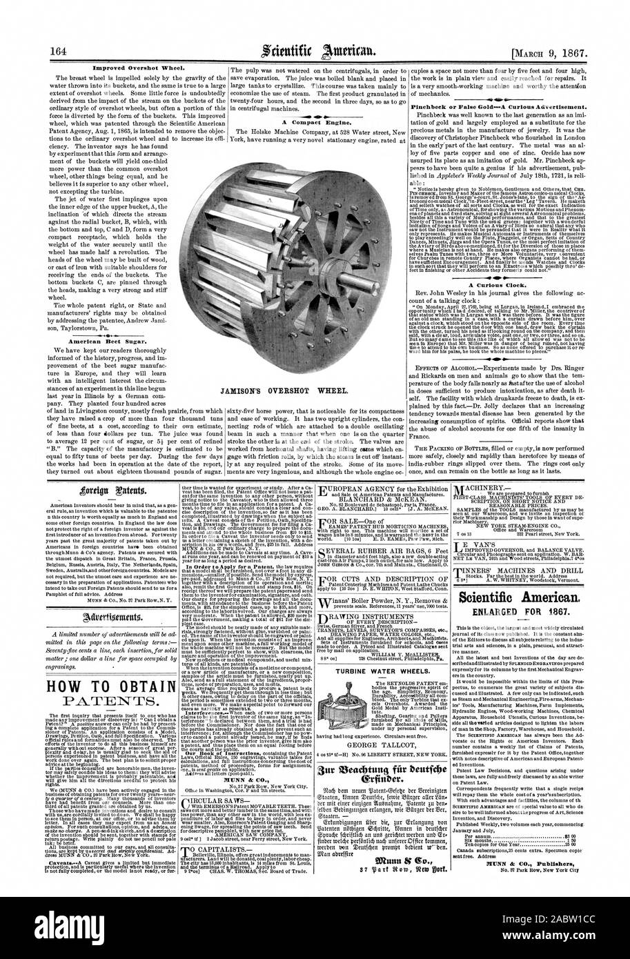
The Overshot Water Wheel Design is the most common type of waterwheel design. The overshot waterwheel is more complicated in its construction and design than the previous undershot waterwheel as it uses buckets or small compartments to both catch and hold the water.
These buckets fill with water flowing onto the wheel through a penstock design above. The gravitational weight of the water in the full buckets causes the wheel to rotate around its central axis as the empty buckets on the other side of the wheel become lighter.
This type of water wheel uses gravity to improve output as well as the water itself, thus overshot waterwheels are much more efficient than undershot designs as almost all of the water and its weight is being used to produce output power. However as before, the waters energy is used only once to rotate the wheel, after which it flows away with the rest of the water.
Overshot waterwheels are suspended above a river or stream and are generally built on the sides of hills providing a water supply from above with a low head (the vertical distance between the water at the top and the river or stream below) of between 5-to-20 metres. A small dam or weir can be constructed and used to both channel and increase the speed of the water to the top of the wheel giving it more energy but it is the volume of water rather than its speed which helps rotate the wheel.
Generally, overshot waterwheels are built as large as possible to give the greatest possible head distance for the gravitational weight of the water to rotate the wheel. However, large diameter waterwheels are more complicated and expensive to construct due to the weight of the wheel and water.
Once the bucket is empty of water it continues around the rotating wheel until it gets back up to the top again ready to be filled with more water and the cycle repeats. One of the disadvantages of an overshot waterwheel design is that the water is only used once as it flows over the wheel.
The Pitchback Water Wheel Design is a variation on the previous overshot waterwheel as it also uses the gravitational weight of the water to help rotate the wheel, but it also uses the flow of the waste water below it to give an extra push. This type of waterwheel design uses a low head infeed system which provides the water near to the top of the wheel from a pentrough above.
Unlike the overshot waterwheel which channelled the water directly over the wheel causing it to rotate in the direction of the flow of the water, the pitchback waterwheel feeds the water vertically downwards through a funnel and into the bucket below causing the wheel to rotate in the opposite direction to the flow of the water above.
Just like the previous overshot waterwheel, the gravitational weight of the water in the buckets causes the wheel to rotate but in an anti-clockwise direction. As the angle of rotation nears the bottom of the wheel, the water trapped inside the buckets empties out below. As the empty bucket is attached to the wheel, it continues rotating with the wheel as before until it gets back up to the top again ready to be filled with more water and the cycle repeats.
The difference this time is that the waste water emptied out of the rotating bucket flows away in the direction of the rotating wheel (as it has nowhere else to go), similar to the undershot waterwheel principal. Thus the main advantage of the pitchback waterwheel is that it uses the energy of the water twice, once from above and once from below to rotate the wheel around its central axis.
The result is that the efficiency of the waterwheel design is greatly increased to over 80% of the waters energy as it is driven by both the gravitaional weight of the incoming water and by the force or pressure of water directed into the buckets from above, as well as the flow of the waste water below pushing against the buckets. The disadvantage though of an pitchback waterwheel is that it needs a slightly more complex water supply arrangement directly above the wheel with chutes and pentroughs.
The Breastshot Water Wheel Design is another vertically-mounted waterwheel design where the water enters the buckets about half way up at axle height, or just above it, and then flows out at the bottom in the direction of the wheels rotation. Generally, the breastshot waterwheel is used in situations were the head of water is insufficient to power an overshot or pitchback waterwheel design from above.
The disadvantage here is that the gravitational weight of the water is only used for about one quarter of the rotation unlike previously which was for half the rotation. To overcome this low head height, the waterwheels buckets are made wider to extract the required amount of potential energy from the water.
Breastshot waterwheels use about the same gravitational weight of the water to rotate the wheel but as the head height of the water is around half that of a typical overshot waterwheel, the buckets are a lot wider than previous waterwheel designs to increase the volume of the water caught in the buckets.
The disadvantage of this type of design is an increase in the width and weight of the water being carried by each bucket. As with the pitchback design, the breastshot wheel uses the energy of the water twice as the waterwheel is designed to sit in the water allowing the waste water to help in the rotation of the wheel as it flows away down stream.
Historically water wheels have been used for milling flour, cereals and other such mechanical tasks. But water wheels can also be used for the generation of electricity, called a Hydro Power system.
By connecting an electrical generator to the waterwheels rotating shaft, either directly or indirectly using drive belts and pulleys, waterwheels can be used to generate power continuously 24 hours a day unlike solar energy. If the waterwheel is designed correctly, a small or “micro” hydroelectric system can produce enough electricity to power lighting and/or electrical appliances in an average home.
Look for Water wheel Generators designed to produce its optimum output at relatively low speeds. For small projects, a small DC motor can be used as a low-speed generator or an automotive alternator but these are designed to work at much higher speeds so some form of gearing may be required. A wind turbine generator makes an ideal waterwheel generator as it is designed for low speed, high output operation.
If there is a fairly fast flowing river or stream near to your home or garden which you can use, then a small scale hydro power system may be a better alternative to other forms of renewable energy sources such as “Wind Energy” or “Solar Energy” as it has a lot less visual impact. Also just like wind and solar energy, with a grid-connected small scale waterwheel designed generating system connected to the local utility grid, any electricity you generate but don’t use can be sold back to the electricity company.
In the next tutorial about Hydro Energy, we will look at the different types of turbines available which we could attach to our waterwheel design for hydro power generation. For more information about Waterwheel Design and how to generate your own electricity using the power of water, or obtain more hydro energy information about the various waterwheel designs available, or to explore the advantages and disadvantages of hydro energy, then Click Here to order your copy from Amazon today about the principles and construction of waterwheels which can be used for generating electricity.

Waterwheel Factory shares it"s knowledge about waterwheels and displays the inherent beauty of a moving waterwheel. Explore; water wheels in history; waterwheel calculations; waterwheels for energy, and gristmill restorations. Explore the many ways you can enjoy having your own waterwheel for landscape decoration or any project you may have in mind.Sit back, relax, and enjoy the many exciting photo’s and options we offer.

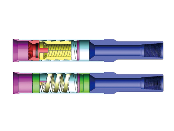
Wireline core drilling tool ezy lock overshot assembly is mainly catch with spear head point of core barrel assembly, it is ideal for surface applications when hoisting above ground.
Ezy lock overshot for wireline drilling is a very useful tool to lift the head assembly with inner tube out of the hole after the inner tube is full of core samples or when we need to retrieve the inner tube head assembly out of the hole. Here we did some innovation and upgrading to the traditional design, after improved, it can reduce the spare parts numbers, so our customers don’t need to order more spare parts than before, it ensures the ezy lock overshot could be solider and easy to be used in practice.
A water wheel is a machine for converting the energy of flowing or falling water into useful forms of power, often in a watermill. A water wheel consists of a wheel (usually constructed from wood or metal), with a number of blades or buckets arranged on the outside rim forming the driving car. Water wheels were still in commercial use well into the 20th century but they are no longer in common use. Uses included milling flour in gristmills, grinding wood into pulp for papermaking, hammering wrought iron, machining, ore crushing and pounding fibre for use in the manufacture of cloth.
Some water wheels are fed by water from a mill pond, which is formed when a flowing stream is dammed. A channel for the water flowing to or from a water wheel is called a mill race. The race bringing water from the mill pond to the water wheel is a headrace; the one carrying water after it has left the wheel is commonly referred to as a tailrace.
Waterwheels were used for various purposes from agriculture to metallurgy in ancient civilizations spanning the Hellenistic Greek world, Rome, China and India. Waterwheels saw continued use in the Post-classical age, like the Middle Ages of Europe and the Islamic Golden Age, but also elsewhere. In the mid to late 18th century John Smeaton"s scientific investigation of the water wheel led to significant increases in efficiency supplying much needed power for the Industrial Revolution.turbine, developed by Benoît Fourneyron, beginning with his first model in 1827.elevations, that exceed the capability of practical-sized waterwheels.
The main difficulty of water wheels is their dependence on flowing water, which limits where they can be located. Modern hydroelectric dams can be viewed as the descendants of the water wheel, as they too take advantage of the movement of water downhill.
Overshot and backshot water wheels are typically used where the available height difference is more than a couple of meters. Breastshot wheels are more suited to large flows with a moderate head. Undershot and stream wheel use large flows at little or no head.
There is often an associated millpond, a reservoir for storing water and hence energy until it is needed. Larger heads store more gravitational potential energy for the same amount of water so the reservoirs for overshot and backshot wheels tend to be smaller than for breast shot wheels.
Overshot and pitchback water wheels are suitable where there is a small stream with a height difference of more than 2 metres (6.5 ft), often in association with a small reservoir. Breastshot and undershot wheels can be used on rivers or high volume flows with large reservoirs.
Stream wheels are cheaper and simpler to build and have less of an environmental impact, than other types of wheels. They do not constitute a major change of the river. Their disadvantages are their low efficiency, which means that they generate less power and can only be used where the flow rate is sufficient. A typical flat board undershot wheel uses about 20 percent of the energy in the flow of water striking the wheel as measured by English civil engineer John Smeaton in the 18th century.
An undershot wheel is a vertically mounted water wheel with a horizontal axle that is rotated by the water from a low weir striking the wheel in the bottom quarter. Most of the energy gain is from the movement of the water and comparatively little from the head. They are similar in operation and design to stream wheels.
The word breastshot is used in a variety of ways. Some authors restrict the term to wheels where the water enters at about the 10 o’clock position, others 9 o’clock, and others for a range of heights.
The small clearance between the wheel and the masonry requires that a breastshot wheel has a good trash rack ("screen" in British English) to prevent debris from jamming between the wheel and the apron and potentially causing serious damage.
Breastshot wheels are less efficient than overshot and backshot wheels but they can handle high flow rates and consequently high power. They are preferred for steady, high-volume flows such as are found on the Fall Line of the North American East Coast. Breastshot wheels are the most common type in the United States of America
A vertically mounted water wheel that is rotated by water entering buckets just past the top of the wheel is said to be overshot. The term is sometimes, erroneously, applied to backshot wheels, where the water goes down behind the wheel.
A typical overshot wheel has the water channeled to the wheel at the top and slightly beyond the axle. The water collects in the buckets on that side of the wheel, making it heavier than the other "empty" side. The weight turns the wheel, and the water flows out into the tail-water when the wheel rotates enough to invert the buckets. The overshot design is very efficient, it can achieve 90%,
Nearly all of the energy is gained from the weight of water lowered to the tailrace although a small contribution may be made by the kinetic energy of the water entering the wheel. They are suited to larger heads than the other type of wheel so they are ideally suited to hilly countries. However even the largest water wheel, the Laxey Wheel in the Isle of Man, only utilises a head of around 30 m (100 ft). The world"s largest head turbines, Bieudron Hydroelectric Power Station in Switzerland, utilise about 1,869 m (6,132 ft).
Overshot wheels require a large head compared to other types of wheel which usually means significant investment in constructing the headrace. Sometimes the final approach of the water to the wheel is along a flume or penstock, which can be lengthy.
A backshot wheel (also called pitchback) is a variety of overshot wheel where the water is introduced just before the summit of the wheel. In many situations, it has the advantage that the bottom of the wheel is moving in the same direction as the water in the tailrace which makes it more efficient. It also performs better than an overshot wheel in flood conditions when the water level may submerge the bottom of the wheel. It will continue to rotate until the water in the wheel pit rises quite high on the wheel. This makes the technique particularly suitable for streams that experience significant variations in flow and reduces the size, complexity, and hence cost of the tailrace.
The direction of rotation of a backshot wheel is the same as that of a breastshot wheel but in other respects, it is very similar to the overshot wheel. See below.
Some wheels are overshot at the top and backshot at the bottom thereby potentially combining the best features of both types. The photograph shows an example at Finch Foundry in Devon, UK. The head race is the overhead timber structure and a branch to the left supplies water to the wheel. The water exits from under the wheel back into the stream.
A special type of overshot/backshot wheel is the reversible water wheel. This has two sets of blades or buckets running in opposite directions so that it can turn in either direction depending on which side the water is directed. Reversible wheels were used in the mining industry in order to power various means of ore conveyance. By changing the direction of the wheel, barrels or baskets of ore could be lifted up or lowered down a shaft or inclined plane. There was usually a cable drum or a chain basket on the axle of the wheel. It is essential that the wheel have braking equipment to be able to stop the wheel (known as a braking wheel). The oldest known drawing of a reversible water wheel was by Georgius Agricola and dates to 1556.
The earliest waterwheel working like a lever was described by Zhuangzi in the late Warring States period (476-221 BC). It says that the waterwheel was invented by Zigong, a disciple of Confucius in the 5th century BC.Chinese of the Eastern Han Dynasty were using water wheels to crush grain in mills and to power the piston-bellows in forging iron ore into cast iron.
In the text known as the Xin Lun written by Huan Tan about 20 AD (during the usurpation of Wang Mang), it states that the legendary mythological king known as Fu Xi was the one responsible for the pestle and mortar, which evolved into the tilt-hammer and then trip hammer device (see trip hammer). Although the author speaks of the mythological Fu Xi, a passage of his writing gives hint that the water wheel was in widespread use by the 1st century AD in China (Wade-Giles spelling):
Fu Hsi invented the pestle and mortar, which is so useful, and later on it was cleverly improved in such a way that the whole weight of the body could be used for treading on the tilt-hammer (tui), thus increasing the efficiency ten times. Afterwards the power of animals—donkeys, mules, oxen, and horses—was applied by means of machinery, and water-power too used for pounding, so that the benefit was increased a hundredfold.
In the year 31 AD, the engineer and Prefect of Nanyang, Du Shi (d. 38), applied a complex use of the water wheel and machinery to power the bellows of the blast furnace to create cast iron. Du Shi is mentioned briefly in the Hou Han Shu) as follows (in Wade-Giles spelling):
In the seventh year of the Chien-Wu reign period (31 AD) Tu Shih was posted to be Prefect of Nanyang. He was a generous man and his policies were peaceful; he destroyed evil-doers and established the dignity (of his office). Good at planning, he loved the common people and wished to save their labor. He invented a water-power reciprocator (shui phai) for the casting of (iron) agricultural implements. Those who smelted and cast already had the push-bellows to blow up their charcoal fires, and now they were instructed to use the rushing of the water (chi shui) to operate it ... Thus the people got great benefit for little labor. They found the "water(-powered) bellows" convenient and adopted it widely.
Water wheels in China found practical uses such as this, as well as extraordinary use. The Chinese inventor Zhang Heng (78–139) was the first in history to apply motive power in rotating the astronomical instrument of an armillary sphere, by use of a water wheel.mechanical engineer Ma Jun (c. 200–265) from Cao Wei once used a water wheel to power and operate a large mechanical puppet theater for the Emperor Ming of Wei (r. 226–239).
The ancient Greeks invented the waterwheel independently and used it in nearly all of the forms and functions described above, including its application for watermilling.Hellenistic period between the 3rd and 1st century BC.
The earliest literary reference to a water-driven, compartmented wheel appears in the technical treatise Pneumatica (chap. 61) of the Greek engineer Philo of Byzantium (ca. 280−220 BC).Parasceuastica (91.43−44), Philo advises the use of such wheels for submerging siege mines as a defensive measure against enemy sapping.dry docks in Alexandria under the reign of Ptolemy IV (221−205 BC).papyri of the 3rd to 2nd century BC mention the use of these wheels, but don"t give further details.Ancient Near East before Alexander"s conquest can be deduced from its pronounced absence from the otherwise rich oriental iconography on irrigation practices.
The earliest depiction of a compartmented wheel is from a tomb painting in Ptolemaic Egypt which dates to the 2nd century BC. It shows a pair of yoked oxen driving the wheel via a sakia gear, which is here for the first time attested, too.Museum of Alexandria, at the time the most active Greek research center, may have been involved in its invention.Alexandrian War in 48 BC tells of how Caesar"s enemies employed geared waterwheels to pour sea water from elevated places on the position of the trapped Romans.
The Romans used waterwheels extensively in mining projects, with enormous Roman-era waterwheels found in places like modern-day Spain. They were reverse overshot water-wheels designed for dewatering deep underground mines.Vitruvius, including the reverse overshot water-wheel and the Archimedean screw. Many were found during modern mining at the copper mines at Rio Tinto in Spain, one system involving 16 such wheels stacked above one another so as to lift water about 80 feet from the mine sump. Part of such a wheel was found at Dolaucothi, a Roman gold mine in south Wales in the 1930s when the mine was briefly re-opened. It was found about 160 feet below the surface, so must have been part of a similar sequence as that discovered at Rio Tinto. It has recently been carbon dated to about 90 AD, and since the wood from which it was made is much older than the deep mine, it is likely that the deep workings were in operation perhaps 30–50 years after. It is clear from these examples of drainage wheels found in sealed underground galleries in widely separated locations that building water wheels was well within their capabilities, and such verticals water wheels commonly used for industrial purposes.
Taking indirect evidence into account from the work of the Greek technician Apollonius of Perge, the British historian of technology M.J.T. Lewis dates the appearance of the vertical-axle watermill to the early 3rd century BC, and the horizontal-axle watermill to around 240 BC, with Byzantium and Alexandria as the assigned places of invention.Strabon (ca. 64 BC–AD 24) to have existed sometime before 71 BC in the palace of the Pontian king Mithradates VI Eupator, but its exact construction cannot be gleaned from the text (XII, 3, 30 C 556).
About the same time, the overshot wheel appears for the first time in a poem by Antipater of Thessalonica, which praises it as a labour-saving device (IX, 418.4–6).Lucretius (ca. 99–55 BC) who likens the rotation of the waterwheel to the motion of the stars on the firmament (V 516).central Gaul.Barbegal watermill complex a series of sixteen overshot wheels was fed by an artificial aqueduct, a proto-industrial grain factory which has been referred to as "the greatest known concentration of mechanical power in the ancient world".
Apart from its use in milling and water-raising, ancient engineers applied the paddled waterwheel for automatons and in navigation. Vitruvius (X 9.5–7) describes multi-geared paddle wheels working as a ship odometer, the earliest of its kind. The first mention of paddle wheels as a means of propulsion comes from the 4th–5th century military treatise
The earliest excavated water wheel driven by tidal power was the Nendrum Monastery mill in Northern Ireland which has been dated to 787, although a possible earlier mill dates to 619. Tide mills became common in estuaries with a good tidal range in both Europe and America generally using undershot wheels.
Cistercian monasteries, in particular, made extensive use of water wheels to power watermills of many kinds. An early example of a very large water wheel is the still extant wheel at the early 13th century Real Monasterio de Nuestra Senora de Rueda, a Cistercian monastery in the Aragon region of Spain. Grist mills (for corn) were undoubtedly the most common, but there were also sawmills, fulling mills and mills to fulfil many other labour-intensive tasks. The water wheel remained competitive with the steam engine well into the Industrial Revolution. At around the 8th to 10th century, a number of irrigation technologies were brought into Spain and thus introduced to Europe. One of those technologies is the Noria, which is basically a wheel fitted with buckets on the peripherals for lifting water. It is similar to the undershot water wheel mentioned later in this article. It allowed peasants to power watermills more efficiently. According to Thomas Glick"s book, Irrigation and Society in Medieval Valencia, the Noria probably originated from somewhere in Persia. It has been used for centuries before the technology was brought into Spain by Arabs who had adopted it from the Romans. Thus the distribution of the Noria in the Iberian peninsula "conforms to the area of stabilized Islamic settlement".Spaniards, the technology spread to the New World in Mexico and South America following Spanish expansion
The type of water wheel selected was dependent upon the location. Generally if only small volumes of water and high waterfalls were available a millwright would choose to use an overshot wheel. The decision was influenced by the fact that the buckets could catch and use even a small volume of water.
The water mill was used for grinding grain, producing flour for bread, malt for beer, or coarse meal for porridge.fulling mill, which was used for cloth making. The trip hammer was also used for making wrought iron and for working iron into useful shapes, an activity that was otherwise labour-intensive. The water wheel was also used in papermaking, beating material to a pulp. In the 13th century water mills used for hammering throughout Europe improved the productivity of early steel manufacturing. Along with the mastery of gunpowder, waterpower provided European countries worldwide military leadership from the 15th century.
Millwrights distinguished between the two forces, impulse and weight, at work in water wheels long before 18th-century Europe. Fitzherbert, a 16th-century agricultural writer, wrote "druieth the wheel as well as with the weight of the water as with strengthe [impulse]".Leonardo da Vinci also discussed water power, noting "the blow [of the water] is not weight, but excites a power of weight, almost equal to its own power".laws of force. Evangelista Torricelli"s work on water wheels used an analysis of Galileo"s work on falling bodies, that the velocity of a water sprouting from an orifice under its head was exactly equivalent to the velocity a drop of water acquired in falling freely from the same height.
The most powerful water wheel built in the United Kingdom was the 100 hp Quarry Bank Mill water wheel near Manchester. A high breastshot design, it was retired in 1904 and replaced with several turbines. It has now been restored and is a museum open to the public.
The biggest working water wheel in mainland Britain has a diameter of 15.4 m (51 ft) and was built by the De Winton company of Caernarfon. It is located within the Dinorwic workshops of the National Slate Museum in Llanberis, North Wales.
The largest working water wheel in the world is the Laxey Wheel (also known as Lady Isabella) in the village of Laxey, Isle of Man. It is 72 feet 6 inches (22.10 m) in diameter and 6 feet (1.83 m) wide and is maintained by Manx National Heritage.
During the Industrial Revolution, in the first half of the 19th century engineers started to design better wheels. In 1823 Jean-Victor Poncelet invented a very efficient undershot wheel design that could work on very low heads, which was commercialized and became popular by late 1830s. Other designs, as the Sagebien wheel, followed later. At the same time Claude Burdin was working on a radically different machine which he called turbine, and his pupil Benoît Fourneyron designed the first commercial one in the 1830s.
Development of water turbines led to decreased popularity of water wheels. The main advantage of turbines is that its ability to harness head is much greater than the diameter of the turbine, whereas a water wheel cannot effectively harness head greater than its diameter. The migration from water wheels to modern turbines took about one hundred years.
Water wheels were used to power sawmills, grist mills and for other purposes during development of the United States. The 40 feet (12 m) diameter water wheel at McCoy, Colorado, built in 1922, is a surviving one out of many which lifted water for irrigation out of the Colorado River.
Two early improvements were suspension wheels and rim gearing. Suspension wheels are constructed in the same manner as a bicycle wheel, the rim being supported under tension from the hub- this led to larger lighter wheels than the former design where the heavy spokes were under compression. Rim-gearing entailed adding a notched wheel to the rim or shroud of the wheel. A stub gear engaged the rim-gear and took the power into the mill using an independent line shaft. This removed the rotative stress from the axle which could thus be lighter, and also allowed more flexibility in the location of the power train. The shaft rotation was geared up from that of the wheel which led to less power loss. An example of this design pioneered by Thomas Hewes and refined by William Armstrong Fairburn can be seen at the 1849 restored wheel at the Portland Basin Canal Warehouse.
Australia has a relatively dry climate, nonetheless, where suitable water resources were available, water wheels were constructed in 19th-century Australia. These were used to power sawmills, flour mills, and stamper batteries used to crush gold-bearing ore. Notable examples of water wheels used in gold recovery operations were the large Garfield water wheel near Chewton—one of at least seven water wheels in the surrounding area—and the two water wheels at Adelong Falls; some remnants exist at both sites.Walhalla once had at least two water wheels, one of which was rolled to its site from Port Albert, on its rim using a novel trolley arrangement, taking nearly 90 days.water wheel at Jindabyne, constructed in 1847, was the first machine used to extract energy—for flour milling—from the Snowy River.
The early history of the watermill in India is obscure. Ancient Indian texts dating back to the 4th century BC refer to the term cakkavattaka (turning wheel), which commentaries explain as arahatta-ghati-yanta (machine with wheel-pots attached). On this basis, Joseph Needham suggested that the machine was a noria. Terry S. Reynolds, however, argues that the "term used in Indian texts is ambiguous and does not clearly indicate a water-powered device." Thorkild Schiøler argued that it is "more likely that these passages refer to some type of tread- or hand-operated water-lifting device, instead of a water-powered water-lifting wheel."
According to Greek historical tradition, India received water-mills from the Roman Empire in the early 4th century AD when a certain Metrodoros introduced "water-mills and baths, unknown among them [the Brahmans] till then".ancient India, predating, according to Pacey, its use in the later Roman Empire or China,
Around 1150, the astronomer Bhaskara Achārya observed water-raising wheels and imagined such a wheel lifting enough water to replenish the stream driving it, effectively, a perpetual motion machine.Arabic and Persian works. During medieval times, the diffusion of Indian and Persian irrigation technologies gave rise to an advanced irrigation system which bought about economic growth and also helped in the growth of material culture.
After the spread of Islam engineers of the Islamic world continued the water technologies of the ancient Near East; as evident in the excavation of a canal in the Basra region with remains of a water wheel dating from the 7th century. Hama in Syria still preserves some of its large wheels, on the river Orontes, although they are no longer in use.Murcia in Spain, La Nora, and although the original wheel has been replaced by a steel one, the Moorish system during al-Andalus is otherwise virtually unchanged. Some medieval Islamic compartmented water wheels could lift water as high as 30 metres (100 ft).Muhammad ibn Zakariya al-Razi"s Kitab al-Hawi in the 10th century described a noria in Iraq that could lift as much as 153,000 litres per hour (34,000 imp gal/h), or 2,550 litres per minute (560 imp gal/min). This is comparable to the output of modern norias in East Asia, which can lift up to 288,000 litres per hour (63,000 imp gal/h), or 4,800 litres per minute (1,100 imp gal/min).
The industrial uses of watermills in the Islamic world date back to the 7th century, while horizontal-wheeled and vertical-wheeled water mills were both in widespread use by the 9th century. A variety of industrial watermills were used in the Islamic world, including gristmills, hullers, sawmills, shipmills, stamp mills, steel mills, sugar mills, and tide mills. By the 11th century, every province throughout the Islamic world had these industrial watermills in operation, from al-Andalus and North Africa to the Middle East and Central Asia.crankshafts and water turbines, gears in watermills and water-raising machines, and dams as a source of water, used to provide additional power to watermills and water-raising machines.factory complexes built in al-Andalus between the 11th and 13th centuries.
The engineers of the Islamic world developed several solutions to achieve the maximum output from a water wheel. One solution was to mount them to piers of bridges to take advantage of the increased flow. Another solution was the shipmill, a type of water mill powered by water wheels mounted on the sides of ships moored in midstream. This technique was employed along the Tigris and Euphrates rivers in 10th-century Iraq, where large shipmills made of teak and iron could produce 10 tons of flour from corn every day for the granary in Baghdad.flywheel mechanism, which is used to smooth out the delivery of power from a driving device to a driven machine, was invented by Ibn Bassal (fl. 1038–1075) of Al-Andalus; he pioneered the use of the flywheel in the saqiya (chain pump) and noria.Al-Jazari in the 13th century and Taqi al-Din in the 16th century described many inventive water-raising machines in their technological treatises. They also employed water wheels to power a variety of devices, including various water clocks and automata.
A recent development of the breastshot wheel is a hydraulic wheel which effectively incorporates automatic regulation systems. The Aqualienne is one example. It generates between 37 kW and 200 kW of electricity from a 20 m3 (710 cu ft) waterflow with a head of 1 to 3.5 m (3 to 11 ft).
Overshot (and particularly backshot) wheels are the most efficient type; a backshot steel wheel can be more efficient (about 60%) than all but the most advanced and well-constructed turbines. In some situations an overshot wheel is preferable to a turbine.
The development of the hydraulic turbine wheels with their improved efficiency (>67%) opened up an alternative path for the installation of water wheels in existing mills, or redevelopment of abandoned mills.
The kinetic energy can be accounted for by converting it into an equivalent head, the velocity head, and adding it to the actual head. For still water the velocity head is zero, and to a good approximation it is negligible for slowly moving water, and can be ignored. The velocity in the tail race is not taken into account because for a perfect wheel the water would leave with zero energy which requires zero velocity. That is impossible, the water has to move away from the wheel, and represents an unavoidable cause of inefficiency.
The power is how fast that energy is delivered which is determined by the flow rate. It has been estimated that the ancient donkey or slave-powered quern of Rome made about one-half of a horsepower, the horizontal waterwheel creating slightly more than one-half of a horsepower, the undershot vertical waterwheel produced about three horsepower, and the medieval overshot waterwheel produced up to forty to sixty horsepower.
A parallel development is the hydraulic wheel/part reaction turbine that also incorporates a weir into the centre of the wheel but uses blades angled to the water flow.
Müller, G.; Wolter, C. (2004). "The breastshot waterwheel: design and model tests" (PDF). Proceedings of the Institution of Civil Engineers - Engineering Sustainability. 157 (4): 203–211. doi:10.1680/ensu.2004.157.4.203. ISSN 1478-4629 – via Semantic Scholar.
Wikander 2000, p. 395; Oleson 2000, p. 229It is no surprise that all the water-lifting devices that depend on subdivided wheels or cylinders originate in the sophisticated, scientifically advanced Hellenistic period, ...
An isolated passage in the Hebrew Deuteronomy (11.10−11) about Egypt as a country where you sowed your seed and watered it with your feet is interpreted as an metaphor referring to the digging of irrigation channels rather than treading a waterwheel (Oleson 2000, pp. 234).
As for a Mesopotamian connection: Schioler 1973, p. 165−167: References to water-wheels in ancient Mesopotamia, found in handbooks and popular accounts, are for the most part based on the false assumption that the Akkadian equivalent of the logogram GIS.APIN was nartabu and denotes an instrument for watering ("instrument for making moist").As a result of his investigations, Laessoe writes as follows on the question of the saqiya: "I consider it unlikely that any reference to the saqiya will appear in ancient Mesopotamian sources." In his opinion, we should turn our attention to Alexandria, "where it seems plausible to assume that the saqiya was invented."
Adriana de Miranda (2007), Water architecture in the lands of Syria: the water-wheels, L"Erma di Bretschneider, pp. 48f, ISBN 978-8882654337 concludes that the Akkadian passages "are counched in terms too general too allow any conclusion as to the excat structure" of the irrigation apparatus, and states that "the latest official Chicago Assyrian Dictionary reports meanings not related to types of irrigation system".
Terry S, Reynolds, Stronger than a Hundred Men; A History of the Vertical Water Wheel. Baltimore; Johns Hopkins University Press, 1983. Robert, Friedel, A Culture of Improvement. MIT Press. Cambridge, Massachusetts. London, England. (2007). p. 33.
Leonardo da Vinci, MS F, 44r, in Les manuscrits de Leonardo da Vinci, ed Charles Ravaisson-Moilien (Paris, 1889), vol.4; cf, Codex Madrid, vol. 1, 69r [The Madrid Codices], trans. And transcribed by Ladislao Reti (New York, 1974), vol. 4.
*Nevell, Mike; Walker (2001). Portland Basin and the archaeology of the Canal Warehouse. Tameside Metropolitan Borough with University of Manchester Archaeological Unit. ISBN 978-1-871324-25-9.
Davies, Peter; Lawrence, Susan (2013). "The Garfield water wheel: hydraulic power on the Victorian goldfields" (PDF). Australasian Historical Archaeology. 31: 25–32.
Wikander 2000, p. 400: This is also the period when water-mills started to spread outside the former Empire. According to Cedrenus (Historiarum compendium), a certain Metrodoros who went to India in c. A.D. 325 "constructed water-mills and baths, unknown among them [the Brahmans] till then".
Gies, Frances; Gies, Joseph (1994). Cathedral, Forge, and Waterwheel: Technology and Invention in the Middle Ages. HarperCollins Publishers. p. 115. ISBN 0060165901.
al-Hassani, S.T.S., Woodcock, E. and Saoud, R. (2006) 1001 inventions : Muslim heritage in our world, Manchester : Foundation for Science Technology and Civilisation, ISBN 0-9552426-0-6
Donners, K.; Waelkens, M.; Deckers, J. (2002), "Water Mills in the Area of Sagalassos: A Disappearing Ancient Technology", Anatolian Studies, Anatolian Studies, Vol. 52, vol. 52, pp. 1–17, doi:10.2307/3643076, JSTOR 3643076, S2CID 163811541
Greene, Kevin (2000), "Technological Innovation and Economic Progress in the Ancient World: M.I. Finley Re-Considered", The Economic History Review, vol. 53, no. 1, pp. 29–59, doi:10.1111/1468-0289.00151
Needham, J. (1965) Science and Civilization in China – Vol. 4: Physics and physical technology – Part 2: Mechanical engineering, Cambridge University Press, ISBN 0-521-05803-1
Oleson, John Peter (1984), Greek and Roman Mechanical Water-Lifting Devices: The History of a Technology, University of Toronto Press, ISBN 978-90-277-1693-4
Quaranta Emanuele, Revelli Roberto (2015), "Performance characteristics, power losses and mechanical power estimation for a breastshot water wheel", Energy, Energy, Elsevier, 87: 315–325, doi:10.1016/j.energy.2015.04.079
Oleson, John Peter (2000), "Wate


 8613371530291