
overshot runway meaning manufacturer
It means that the aircraft has touched down on the runway before going off it. Overshoot is used in the same sense (note that overrun/overshoot occurs both in TO/landing).
However, there is one case where they are used differently. Overshooting the runway also can mean that the aircraft has touched beyond the end of the runway i.e. missed the runway entirely.

Summary: New Delhi [India], July 3 (ANI): In the wake of incidents of aircraft overshooting runways, Union Civil Aviation Minister Hardeep Singh Puri on Wednesday said such incidents happen sometimes due to excessive rains but everything is under control and there is no cause of concern.
to cause (an aircraft) to fly or taxi too far along (a runway) during landing or taking off, or (of an aircraft) to fly or taxi too far along a runway

According to the International Civil Aviation Organization (ICAO), a runway is a "defined rectangular area on a land aerodrome prepared for the landing and takeoff of aircraft".asphalt, concrete, or a mixture of both) or a natural surface (grass, dirt, gravel, ice, sand or salt). Runways, taxiways and ramps, are sometimes referred to as "tarmac", though very few runways are built using tarmac. Takeoff and landing areas defined on the surface of water for seaplanes are generally referred to as waterways. Runway lengths are now commonly given in meters worldwide, except in North America where feet are commonly used.
In 1916, in a World War I war effort context, the first concrete-paved runway was built in Clermont-Ferrand in France, allowing local company Michelin to manufacture Bréguet Aviation military aircraft.
For fixed-wing aircraft, it is advantageous to perform takeoffs and landings into the wind to reduce takeoff or landing roll and reduce the ground speed needed to attain flying speed. Larger airports usually have several runways in different directions, so that one can be selected that is most nearly aligned with the wind. Airports with one runway are often constructed to be aligned with the prevailing wind. Compiling a wind rose is in fact one of the preliminary steps taken in constructing airport runways.wind direction is given as the direction the wind is coming from: a plane taking off from runway 09 faces east, into an "east wind" blowing from 090°.
Originally in the 1920s and 1930s, airports and air bases (particularly in the United Kingdom) were built in a triangle-like pattern of three runways at 60° angles to each other. The reason was that back then aviation was only starting, and as a result although it was known that winds affect runway distance required, etc. not much was known about wind behaviour. As a result, three runways in a triangle-like pattern were built, and the runway with the heaviest traffic on it would eventually expand into an airport"s main runway, while the other two runways would be either abandoned or converted into taxiways.Bristol Airport has only one runway—09/27 (9/27)—and two taxiways that form a "V" which may have been runways on the original 1930s RAF Lulsgate Bottom airbase.
Runways are named by a number between 01 and 36, which is generally the magnetic azimuth of the runway"s heading in decadegrees. This heading differs from true north by the local magnetic declination. A runway numbered 09 points east (90°), runway 18 is south (180°), runway 27 points west (270°) and runway 36 points to the north (360° rather than 0°).
FAA airport diagram at O"Hare International Airport. The two 14/32 runways go from upper left to lower right, the two 4/22 runways go from lower left to upper right, and the two 9/27 and three 10/28 runways are horizontal.
A leading zero, for example in "runway zero-six" or "runway zero-one-left", is included for all ICAO and some U.S. military airports (such as Edwards Air Force Base). However, most U.S. civil aviation airports drop the leading zero as required by FAA regulation.Cairns Army Airfield. This American anomaly may lead to inconsistencies in conversations between American pilots and controllers in other countries. It is very common in a country such as Canada for a controller to clear an incoming American aircraft to, for example, runway 04, and the pilot read back the clearance as runway 4. In flight simulation programs those of American origin might apply U.S. usage to airports around the world. For example, runway 05 at Halifax will appear on the program as the single digit 5 rather than 05.
Military airbases may include smaller paved runways known as "assault strips" for practice and training next to larger primary runways.Dobbins Air Reserve Base"s Runway 110/290and Duke Field"s Runway 180/360.
Runways with non-hard surfaces, such as small turf airfields and waterways for seaplanes, may use the standard numerical scheme or may use traditional compass point naming, examples include Ketchikan Harbor Seaplane Base"s Waterway E/W.Santa Catalina Island"s Pebbly Beach Seaplane Base, may designate their landing area as Waterway ALL/WAY to denote the lack of designated landing direction.
If there is more than one runway pointing in the same direction (parallel runways), each runway is identified by appending left (L), center (C) and right (R) to the end of the runway number to identify its position (when facing its direction)—for example, runways one-five-left (15L), one-five-center (15C), and one-five-right (15R). Runway zero-three-left (03L) becomes runway two-one-right (21R) when used in the opposite direction (derived from adding 18 to the original number for the 180° difference when approaching from the opposite direction). In some countries, regulations mandate that where parallel runways are too close to each other, only one may be used at a time under certain conditions (usually adverse weather).
At large airports with four or more parallel runways (for example, at Chicago O"Hare, Los Angeles, Detroit Metropolitan Wayne County, Hartsfield-Jackson Atlanta, Denver, Dallas–Fort Worth and Orlando), some runway identifiers are shifted by 1 to avoid the ambiguity that would result with more than three parallel runways. For example, in Los Angeles, this system results in runways 6L, 6R, 7L, and 7R, even though all four runways are actually parallel at approximately 69°. At Dallas/Fort Worth International Airport, there are five parallel runways, named 17L, 17C, 17R, 18L, and 18R, all oriented at a heading of 175.4°. Occasionally, an airport with only three parallel runways may use different runway identifiers, such as when a third parallel runway was opened at Phoenix Sky Harbor International Airport in 2000 to the south of existing 8R/26L—rather than confusingly becoming the "new" 8R/26L it was instead designated 7R/25L, with the former 8R/26L becoming 7L/25R and 8L/26R becoming 8/26.
Suffixes may also be used to denote special use runways. Airports that have seaplane waterways may choose to denote the waterway on charts with the suffix W; such as Daniel K. Inouye International Airport in Honolulu and Lake Hood Seaplane Base in Anchorage.STOL aircraft (S), gliders (G), rotorcraft (H), and ultralights (U).true north rather than magnetic north will use the suffix T; this is advantageous for certain airfields in the far north such as Thule Air Base.
Runway designations may change over time because Earth"s magnetic lines slowly drift on the surface and the magnetic direction changes. Depending on the airport location and how much drift occurs, it may be necessary to change the runway designation. As runways are designated with headings rounded to the nearest 10°, this affects some runways sooner than others. For example, if the magnetic heading of a runway is 233°, it is designated Runway 23. If the magnetic heading changes downwards by 5 degrees to 228°, the runway remains Runway 23. If on the other hand the original magnetic heading was 226° (Runway 23), and the heading decreased by only 2 degrees to 224°, the runway becomes Runway 22. Because magnetic drift itself is slow, runway designation changes are uncommon, and not welcomed, as they require an accompanying change in aeronautical charts and descriptive documents. When a runway designation does change, especially at major airports, it is often done at night, because taxiway signs need to be changed and the numbers at each end of the runway need to be repainted to the new runway designators. In July 2009 for example, London Stansted Airport in the United Kingdom changed its runway designations from 05/23 to 04/22 during the night.
Runway dimensions vary from as small as 245 m (804 ft) long and 8 m (26 ft) wide in smaller general aviation airports, to 5,500 m (18,045 ft) long and 80 m (262 ft) wide at large international airports built to accommodate the largest jets, to the huge 11,917 m × 274 m (39,098 ft × 899 ft) lake bed runway 17/35 at Edwards Air Force Base in California – developed as a landing site for the Space Shuttle.
The runway thresholds are markings across the runway that denote the beginning and end of the designated space for landing and takeoff under non-emergency conditions.
The runway is the surface from threshold to threshold (including displaced thresholds), which typically features threshold markings, numbers, and centerlines, but excludes blast pads and stopways at both ends.
Blast pads are often constructed just before the start of a runway where jet blast produced by large planes during the takeoff roll could otherwise erode the ground and eventually damage the runway.
Stopways, also known as overrun areas, are also constructed at the end of runways as emergency space to stop planes that overrun the runway on landing or a rejected takeoff.
Blast pads and stopways look similar, and are both marked with yellow chevrons; stopways may optionally be surrounded by red runway lights. The differences are that stopways can support the full weight of an aircraft and are designated for use in an aborted takeoff, while blast pads are often not as strong as the main paved surface of the runway and are not to be used for taxiing, landing, or aborted takeoffs.
takeoff distance available.paved runway is 2,000 metres (6,600 ft) long and there are 400 metres (1,300 ft) of clearway beyond the end of the runway, the takeoff distance available is 2,400 metres (7,900 ft) long. When the runway is to be used for takeoff of a large airplane, the maximum permissible takeoff weight of the airplane can be based on the takeoff distance available, including clearway. Clearway allows large airplanes to take off at a heavier weight than would be allowed if only the length of the paved runway is taken into account.
There are runway markings and signs on most large runways. Larger runways have a distance remaining sign (black box with white numbers). This sign uses a single number to indicate the remaining distance of the runway in thousands of feet. For example, a 7 will indicate 7,000 ft (2,134 m) remaining. The runway threshold is marked by a line of green lights.
Visual runways are used at small airstrips and are usually just a strip of grass, gravel, ice, asphalt, or concrete. Although there are usually no markings on a visual runway, they may have threshold markings, designators, and centerlines. Additionally, they do not provide an instrument-based landing procedure; pilots must be able to see the runway to use it. Also, radio communication may not be available and pilots must be self-reliant.
Non-precision instrument runways are often used at small- to medium-size airports. These runways, depending on the surface, may be marked with threshold markings, designators, centerlines, and sometimes a 1,000 ft (305 m) mark (known as an aiming point, sometimes installed at 1,500 ft (457 m)). While centerlines provide horizontal position guidance, aiming point markers provide vertical position guidance to planes on visual approach.
Precision instrument runways, which are found at medium- and large-size airports, consist of a blast pad/stopway (optional, for airports handling jets), threshold, designator, centerline, aiming point, and 500 ft (152 m), 1,000 ft (305 m)/1,500 ft (457 m), 2,000 ft (610 m), 2,500 ft (762 m), and 3,000 ft (914 m) touchdown zone marks. Precision runways provide both horizontal and vertical guidance for instrument approaches.
In Australia, Canada, the United Kingdom,Hong Kong and Macau) all 3-stripe and 2-stripe touchdown zones for precision runways are replaced with one-stripe touchdown zones.
Runways in Norway have yellow markings instead of the usual white ones. This also occurs in some airports in Japan, Sweden, and Finland. The yellow markings are used to ensure better contrast against snow.
Runways may have different types of equipment on each end. To reduce costs, many airports do not install precision guidance equipment on both ends. Runways with one precision end and any other type of end can install the full set of touchdown zones, even if some are past the midpoint. Runways with precision markings on both ends omit touchdown zones within 900 ft (274 m) of the midpoint, to avoid ambiguity over the end with which the zone is associated.
A line of lights on an airfield or elsewhere to guide aircraft in taking off or coming in to land or an illuminated runway is sometimes also known as a flare path.
Runway lighting are used at airports for use at night and low visibility. Seen from the air, runway lights form an outline of the runway. A runway may have some or all of the following:
Runway end lights – a pair of four lights on each side of the runway on precision instrument runways, these lights extend along the full width of the runway. These lights show green when viewed by approaching aircraft and red when seen from the runway.
Runway centerline lighting system (RCLS) – lights embedded into the surface of the runway at 50 ft (15 m) intervals along the runway centerline on some precision instrument runways. White except the last 900 m (3,000 ft): alternate white and red for next 600 m (1,969 ft) and red for last 300 m (984 ft).
Taxiway centerline lead-off lights – installed along lead-off markings, alternate green and yellow lights embedded into the runway pavement. It starts with green light at about the runway centerline to the position of first centerline light beyond the Hold-Short markings on the taxiway.
Land and hold short lights – a row of white pulsating lights installed across the runway to indicate hold short position on some runways that are facilitating land and hold short operations (LAHSO).
Runway overrun (also known as an overshoot) – a type of excursion where the aircraft is unable to stop before the end of the runway (e.g. Air France Flight 358, TAM Airlines Flight 3054, Air India Express Flight 812).
Runway confusion – an aircraft makes use of the wrong runway for landing or takeoff (e.g. Singapore Airlines Flight 006, Western Airlines Flight 2605).
The choice of material used to construct the runway depends on the use and the local ground conditions. For a major airport, where the ground conditions permit, the most satisfactory type of pavement for long-term minimum maintenance is concrete. Although certain airports have used reinforcement in concrete pavements, this is generally found to be unnecessary, with the exception of expansion joints across the runway where a dowel assembly, which permits relative movement of the concrete slabs, is placed in the concrete. Where it can be anticipated that major settlements of the runway will occur over the years because of unstable ground conditions, it is preferable to install asphalt concrete surface, as it is easier to patch on a periodic basis. Fields with very low traffic of light planes may use a sod surface. Some runways make use of salt flats.
Because airport pavement construction is so expensive, manufacturers aim to minimize aircraft stresses on the pavement. Manufacturers of the larger planes design landing gear so that the weight of the plane is supported on larger and more numerous tires. Attention is also paid to the characteristics of the landing gear itself, so that adverse effects on the pavement are minimized. Sometimes it is possible to reinforce a pavement for higher loading by applying an overlay of asphaltic concrete or portland cement concrete that is bonded to the original slab. Post-tensioning concrete has been developed for the runway surface. This permits the use of thinner pavements and should result in longer concrete pavement life. Because of the susceptibility of thinner pavements to frost heave, this process is generally applicable only where there is no appreciable frost action.
Runway pavement surface is prepared and maintained to maximize friction for wheel braking. To minimize hydroplaning following heavy rain, the pavement surface is usually grooved so that the surface water film flows into the grooves and the peaks between grooves will still be in contact with the aircraft tires. To maintain the macrotexturing built into the runway by the grooves, maintenance crews engage in airfield rubber removal or hydrocleaning in order to meet required FAA friction levels.
A runway of at least 1,800 m (5,900 ft) in length is usually adequate for aircraft weights below approximately 100,000 kg (220,000 lb). Larger aircraft including widebodies will usually require at least 2,400 m (7,900 ft) at sea level. International widebody flights, which carry substantial amounts of fuel and are therefore heavier, may also have landing requirements of 3,200 m (10,500 ft) or more and takeoff requirements of 4,000 m (13,000 ft). The Boeing 747 is considered to have the longest takeoff distance of the more common aircraft types and has set the standard for runway lengths of larger international airports.
At sea level, 3,200 m (10,500 ft) can be considered an adequate length to land virtually any aircraft. For example, at O"Hare International Airport, when landing simultaneously on 4L/22R and 10/28 or parallel 9R/27L, it is routine for arrivals from East Asia, which would normally be vectored for 4L/22R (2,300 m (7,546 ft)) or 9R/27L (2,400 m (7,874 ft)) to request 28R (4,000 m (13,123 ft)). It is always accommodated, although occasionally with a delay. Another example is that the Luleå Airport in Sweden was extended to 3,500 m (11,483 ft) to allow any fully loaded freight aircraft to take off. These distances are also influenced by the runway grade (slope) such that, for example, each 1 percent of runway down slope increases the landing distance by 10 percent.
In India, recommendations of International Civil Aviation Organization (ICAO) are now followed more often. For landing, only altitude correction is done for runway length whereas for take-off, all types of correction are taken into consideration.
"Chapter 2.3.e.(2)". FAA Advisory Circular AC 150/5340-1L - Standards for Airport Markings. p. 17. A single-digit runway landing designation number is never preceded by a zero.

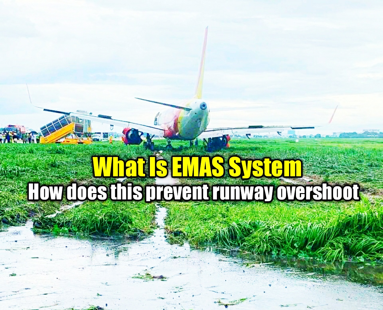
An engineered materials arrestor system, engineered materials arresting system (EMAS), or arrester bedrunway to reduce the severity of the consequences of a runway excursion. Engineered materials are defined in FAA Advisory Circular No 150/5220-22B as "high energy absorbing materials of selected strength, which will reliably and predictably crush under the weight of an aircraft". While the current technology involves lightweight, crushable concrete blocks, any material that has been approved to meet the FAA Advisory Circular can be used for an EMAS. The purpose of an EMAS is to stop an aircraft overrun with no human injury and minimal aircraft damage. The aircraft is slowed by the loss of energy required to crush the EMAS material. An EMAS is similar in concept to the runaway truck ramp or race circuit gravel trap, made of gravel or sand. It is intended to stop an aircraft that has overshot a runway when there is an insufficient free space for a standard runway safety area (RSA). Multiple patents have been issued on the construction and design on the materials and process.
Research projects completed in Europe have looked into the cost-effectiveness of EMAS. Arrestor beds have been installed at airports where the runway safety areas are below standards, and their ability to stop aircraft with minimal or no damage to the air frame and its occupants has proven to bring results far beyond the cost of installations. The latest report, "Estimated Cost-Benefit Analysis of Runway Severity Reduction Based on Actual Arrestments", shows how the money saved through the first 11 arrestments has reached a calculated total of 1.9 billion USD, thus saving more than $1 B over the estimated cost of development (R&D, all installations worldwide, maintenance and repairs reaching a total of USD 600 million). The study suggests that mitigating the consequences of runway excursions worldwide may turn out to be much more cost-effective than the current focus on reducing the already very low probability of occurrence.
The FAA"s design criteria for new airports designate Runway Safety Areas (RSAs) to increase the margin of safety if an overrun occurs and to provide additional access room for response vehicles. A United States federal law required that the length of RSAs in airports was to be 1,000 feet (300 m) by the end of 2015, in a response to a runway overrun into a highway at Teterboro Airport in New Jersey.
Of the 15 non-U.S. installations, eight were provided by Zodiac Arresting Systems (two in China, two in Madrid, one in Taiwan, two in Norway and one in Saudi Arabia), six were provided by RunwaySafe (one in Switzerland, and three in overseas departments of France – one in Reunion Island, two in Mayotte), one in Japan, one in Germany, two in Brazil and one provided by Hankge (China).
The first EMAS was developed in the mid-1990s by ESCO/Engineered Arresting Systems Corp. (later Zodiac Arresting Systems) as part of a collaboration and technical acceptance by the FAA. The fourth generation EMAS arrestor beds are composed of blocks of lightweight, crushable cellular concrete material, encased in jet blast resistant protection, designed to safely stop airplanes that overshoot runways. Zodiac"s EMAS is installed on over 110 airport runways at over 65 airports on three continents.
The Swedish company Runway Safe AB developed an EMAS system, a foamed silica bed made from recycled glass contained within a high-strength plastic mesh system anchored to the pavement at the end of the runway. The foamed silica is poured into lanes bounded by the mesh and covered with a poured cement layer and treated with a top coat of sealant.
On 19 January 2010, a Bombardier CRJ-200 commercial regional airliner with 34 persons aboard overran the runway at Yeager Airport in Charleston, West Virginia after a rejected takeoff.
On 2 November 2011, a Cessna Citation II business aircraft with 5 persons aboard overran the runway at Key West International Airport in Key West, Florida.
In October 2013, a Cessna 680 Citation business aircraft with 8 persons aboard overran the runway at Palm Beach International in West Palm Beach, Florida.
In October 2016, a Boeing 737 aircraft with 37 persons aboard, including Republican vice-presidential candidate Mike Pence, overran the runway at LaGuardia Airport, New York.
On 27 February 2019 an Embraer Phenom 100 operated by Quest Diagnostic Laboratories overran a runway at the Charles B. Wheeler Kansas City Downtown Airport (KMKC) at 4:28am local time resulting in the safe stopping of the aircraft with the pilot being the only occupant aboard.
On 13 October 2006, New York Yankees player Alex Rodriguez"s private jet was brought to a halt safely by the EMAS installation at Bob Hope Airport in Burbank, California. The system was installed after the 2000 Southwest Airlines Flight 1455 runway overshoot that injured 43 passengers and the captain.
Boburg, Shawn (17 September 2013). "Teterboro Airport gets $1M for runway project". northjersey.com. Archived from the original on 5 May 2014. Retrieved 5 May 2014.
Jacobs, Kenneth (1 March 2006). "Runway Safety Areas - An Airport Operator"s Perspective". Federal Aviation Administration. pp. 8, 9, 13. Archived from the original on 27 September 2012. Retrieved 20 August 2014.
"PSA Airlines Canadair CRJ-200 N246PS operating as US Airways flight 2495 from Charleston, West Virginia (CRW) to Charlotte, North Carolina (CLT) with 30 passengers [sic] and 3 crew, overran the runway following a rejected take-off. The aircraft was stopped by the EMAS at the end of the runway, sustaining only minor damage to its landing gear doors."
Mele, Christopher (27 October 2016). "Plane With Mike Pence Aboard Skids Off La Guardia Runway". The New York Times. ISSN 0362-4331. Retrieved 28 October 2016.
Oldham, Jennifer (14 October 2006). "Yankee Player"s Jet Overruns Runway in Burbank". The airport installed the $4-million safety system after a Southwest Airlines Boeing 737 skidded off the same runway and onto a street in 2000, injuring 43 passengers and the captain on the same runway.

Approach – The phase of flight when the pilot intends to land on the runway. There are different types of approaches, depending on whether the pilot is flying VFR or IFR.
Runway End Safety Area (RESA)– A surface located beyond the runway designated as a place for aircraft to enter in an attempt to minimize risk during unplanned occurrences, such as an overshoot.
Touch-and-Go– An aircraft maneuver used to practice landing techniques by simply landing on the runway and taking off once more without coming to a full stop.
Upwind Leg – The flight path in an airport pattern that runs parallel to the runway landing direction, along the same direction the aircraft will be landing.
As hard as we"ve tried over the years, we can"t seem to come up with a definitive way of translating the condition of a runway into a number that we can plug into tables and charts to figure out our likelihood of stopping the airplane in the amount of runway in front of us. Our most recent attempt is known as a "Runway Condition Code" taken from a "Runway Condition Assessment Matrix." So that"s what is shown here. (If this is news to you, it was first unveiled with SAFO 16009.) I"ll follow that with some of the older systems in case you run into them.
Landing overruns that occur on wet runways typically involve multiple contributing factors such as long touchdown, improper use of deceleration devices, tailwind and less available friction than expected. Several recent runway-landing incidents/accidents have raised concerns with wet runway stopping performance assumptions. Analysis of the stopping data from these incidents/accidents indicates the braking coefficient of friction in each case was significantly lower than expected for a wet runway as defined by Title 14 of the Code of Federal Regulations (14 CFR) part 25 § Section 25.109 and Advisory Circular (AC) 25-7D methods. These incidents/accidents occurred on both grooved and un-grooved runways. The data indicates that applying a 15% safety margin to wet runway time-of-arrival advisory data, as recommended by SAFO 06012 (or current guidance), may be inadequate in certain wet runway conditions. Takeoff and Landing Performance Assessment (TALPA) procedures implemented by the FAA on October 1, 2016, added new insight as to how flightcrews can evaluate runway braking performance prior to landing. TALPA defines WET as “Includes damp and 1/8-inch depth or less of water,” while CONTAMINATED is “greater than 1/8-inch of water.”
If you hear your runway is reporting a "3/3/3" is that good? Well it means all three segments of the runway are "medium" so I guess that"s better than a "2/2/2" but not as good as a "5/5/5" as you might suspect. But this is the system we have now and it is actually better than those "mu" or "RCR" numbers of the past in that they are supposed to be more accurate. I"m not so sure, but here is what the book says followed by some added information from the airport management side of the house.
Runway condition code (RwyCC) values range from 1 (poor) to 6 (dry). For frozen contaminants on runway surfaces, a runway condition code reading of 4 indicates the level when braking deceleration or directional control is between good and medium.
Numerical readings may be obtained by using the Runway Condition Assessment Matrix (RCAM). The RCAM provides the airport operator with data to complete the report that includes the following:
Assessments for each zone (see 4−3−9c1(c)) will be issued in the direction of takeoff and landing on the runway, ranging from “1” to “6” to describe contaminated surfaces.
When runway condition code reports are provided by airport management, the ATC facility providing approach control or local airport advisory must provide the report to all pilots.
Pilots should use runway condition code information with other knowledge including aircraft performance characteristics, type, and weight, previous experience, wind conditions, and aircraft tire type (such as bias ply vs. radial constructed) to determine runway suitability.
The Runway Condition Assessment Matrix identifies the descriptive terms “good,” “good to medium,” “medium,” “medium to poor,” “poor,” and “nil” used in braking action reports.
It seems like we"ve replaced highly subjective words ("good," "medium," "poor," and "nil") for seven numbers that may seem equally subjective. It also seems we gave up the science of the "Mu" number that is still used with the ICAO SNOWTAM system. But the change actually has more good than bad. We pilots don"t understand the process as well as we should and are too quick to hear the three magic numbers and stop listening. If you understand how the numbers are produced and the importance of the language that follows, you might have some very useful decision making tools. AC 150/5200-30D is what airport operators use to manage runway and taxiway reporting and snow removal. It has a lot of good information for pilots who want to "read between the lines" when it comes to an RCC.
Following the overrun accident of a Boeing-737 in December of 2005, the FAA found that the current state of the industry practices did not have adequate guidance and regulation addressing operation on non-dry, non-wet runways, i.e., contaminated runways. As such, the FAA chartered an Aviation Rulemaking Committee (ARC) to address Takeoff and Landing Performance Assessment (TALPA) requirements for the appropriate parts 23, 25, 91 subpart K, 121, 125, 135, and 139. In formulating recommendations, it became clear to the ARC that the ability to communicate actual runway conditions to the pilots in real time and in terms that directly relate to expected aircraft performance was critical to the success of the project.
The ARC got it mostly right but we need to keep in mind this was an industry-wide effort and though the business aviation community was represented, the largest users (the airlines) obviously carried more weight. So we got a system that is tailored towards large airports with sophisticated snow removal equipment. The system is also "one size fits all," so terms like "ice" on a runway in Alaska (dry and compacted and therefore rough) is equal to "ice" in New England (covered with a film of supercooled water). So let"s tackle this. Is the RCC a subjective measure? To find out, we should look at the RCAM presented above in AIM (a pilot"s manual) to what the airport operator is given. But you can"t do that unless you understand μ . . .
How about in English? If the surface is very "grippy" and will not allow the object to slide, it can have a coefficient of friction of 1.0 — meaning it would take just as much force to lift the object as it would to push it. If the surface is extremely slippery, it could theoretically have a coefficient of 0.0 — meaning it takes no effort at all the push the object. The coefficient of friction can be greater than 1.0. (Imagine the object velcroed to the surface, for example.)
MU (friction) values range from 0 to 100 where zero is the lowest friction value and 100 is the maximum friction value obtainable. For frozen contaminants on runway surfaces, a MU value of 40 or less is the level when the aircraft braking performance starts to deteriorate and directional control begins to be less responsive. The lower the MU value, the less effective braking performance becomes and the more difficult directional control becomes.
When the MU value for any one-third zone of an active runway is 40 or less, a report should be given to ATC by airport management for dissemination to pilots.
FAA-approved friction measuring equipment may be employed to help in determining the effects of friction-enhancing treatments, in that it can show the trend of a runway as to increasing or decreasing friction. Airport operators should not attempt to correlate friction readings (Mu numbers) to Good/Medium (previously known as Fair)/Poor or Nil runway surface conditions, as no consistent, usable correlation between Mu values and these terms has been shown to exist to the FAA’s satisfaction. It is important to note that while manufacturers of the approved friction measuring equipment may provide a table that correlates braking action to Mu values, these correlations are not acceptable to the FAA. To ensure that data collected are accurate, qualified personnel should use FAA-approved equipment and follow the manufacturer’s instructions for use. Note: It is no longer acceptable to report or disseminate friction (Mu) values to aircraft operators. This includes informal dissemination outside of the NOTAM system. In support of this change the NOTAM system will no longer allow for the reporting of this information. Airplane braking performance cannot be directly related to Friction (Mu) values. Runway Condition Codes, which will be included in the runway condition NOTAM, where applicable, are directly relevant to the determination of required landing distances.
There are two basic types of friction measuring equipment that can be used for conducting friction surveys on runways during winter operations: Continuous Friction Measuring Equipment (CFME) and Decelerometers (DEC).
Continuous Friction Measuring Equipment (CFME). CFME devices are recommended (over Decelerometers) for measuring friction characteristics of pavement surfaces covered with contaminants, as they provide a continuous graphic record of the pavement surface friction characteristics with friction averages for each one-third zone of the runway length.
Decelerometers. Decelerometers are recommended (over CFMEs) for airports where the longer runway downtime required to complete a friction survey is unacceptable and for busy airports where it is difficult to gain access to the full length of a runway crossed by another runway. Decelerometers should be of the electronic type due to the advantages noted below. Mechanical decelerometers may be used, but should be reserved as a backup. Airports having only mechanical devices should plan to upgrade as soon as possible. Neither type of decelerometer will provide a continuous graphic record of friction for the pavement surface condition. They provide only a spot check of the pavement surface. On pavements with frozen contaminant coverage of less than 25 percent, decelerometers are used only on the contaminated areas. For this reason, a survey taken under such conditions will result in a conservative representation of runway braking conditions. This should be considered when using friction values as an input into decisions about runway treatments. In addition, any time a pilot may experience widely varying braking along the runway, it is essential that the percentage of contaminant coverage be noted in any report.
Electronic decelerometers eliminate potential human error by automatically computing and recording friction averages for each one-third zone of the runway. They also provide a printed record of the friction survey data.
Mechanical decelerometers may be used as a backup to an electronic decelerometer. The runway downtime required to complete a friction survey will be longer than with an electronic decelerometer. Mechanical decelerometers do not provide automatic friction averages or a printed copy of data.
Lateral Location. On runways that serve primarily narrow-body airplanes, runway friction surveys should be conducted approximately 10 feet (3 m) from the runway centerline. On runways that serve primarily wide-body airplanes, runway friction surveys should be conducted approximately 20 feet (6 m) from the runway centerline. Unless surface conditions are noticeably different on the two sides of the runway centerline, only one survey is needed, and it may be conducted on either side.
The RCAM is the method by which an airport operator reports a runway surface assessment when contaminants are present. Use of the RCAM is only applicable to paved runway surfaces. Once an assessment has been performed, the RCAM defines the format for which the airport operator reports and receives a runway condition “Code” via the NOTAM System. The reported information allows a pilot to interpret the runway conditions in terms that relate to airplane performance. This approach is a less subjective means of assessing runway conditions by using defined objective criteria. Aircraft manufacturers have determined that variances in contaminant type, depth, and air temperature can cause specific changes in aircraft braking performance. At the core of the RCAM is its ability to differentiate among the performance characteristics of given contaminants.
Conditions Acceptable to Use Decelerometers or Continuous Friction Measuring Equipment to Conduct Runway Friction Surveys on Frozen Contaminated Surfaces.
5.1.4.1. The data obtained from such runway friction surveys are considered to be reliable only when the surface is contaminated under any of the following conditions:
The RCAM is the method by which an airport operator reports a runway surface assessment when contaminants are present. Use of the RCAM is only applicable to paved runway surfaces. Once an assessment has been performed, the RCAM defines the format for which the airport operator reports and receives a runway condition “Code” via the NOTAM System. The reported information allows a pilot to interpret the runway conditions in terms that relate to airplane performance. This approach is a less subjective means of assessing runway conditions by using defined objective criteria.
Airport operators normally access the system through the "NOTAM Manager" application. The first question will be "Is greater than 25% of the overall runway length and width, or cleared width (if not cleared from edge to edge), contaminated?" If the answer is no the only option will be to report contaminant percentage, type, and depth, when applicable, for each third of the runway, as well as any treatment. No Runway Condition Code is reported.
So you"ve got more than 25% coverage. The next thing to do is look at the left column on the RCAM and look for the type and depth of contaminant as well as temperature. Do that for each third of the runway. If only a portion of the runway is cleared (such as the center 75"), you only have to consider that portion. Unless you have upgrades and downgrades, the Runway Condition Codes will enter the system. Notice you didn"t have to do anything with the decelerometer.
If the airport operator thinks the RCC can be upgraded or should be downgraded, they can take a drive with an approved decelerometer. But only RCCs of 1 or 2 can be upgraded and even then they can only be upgraded up to a 3. You can take the decelerometer"s μ reading to upgrade or downgrade the RCC. What about pilot reports? Pilot reports can only be used to downgrade an RCC and only for the portion of the runway experienced.
Downgrade Assessment Criteria. When data from the shaded area in the RCAM (i.e., CFME/deceleration devices, pilot reports, or observations) suggest conditions are worse than indicated by the present contaminant, the airport operator should exercise good judgment and, if warranted, report lower runway condition codes than the contamination type and depth would indicate in the RCAM. While pilot reports (PIREPs) of braking action provide valuable information, these reports rarely apply to the full length of the runway as such evaluations are limited to the specific sections of the runway surface in which wheel braking was utilized. It is not appropriate to use downgrade assessment criteria to upgrade contaminant based assessments of condition codes (e.g., from 2 to 3).
The correlation of the Mu (μ) values with runway conditions and condition codes in the RCAM are only approximate ranges for a generic friction measuring device and are intended to be used for an upgrade or downgrade of a runway condition code. Airport operators should use their best judgment when using friction measuring devices for downgrade assessments, including their experience with the specific measuring devices used.
Pilot Reported Braking Action. This is a report of braking action on the runway, by a pilot, providing other pilots with a degree/quality of expected braking. The braking action experienced is dependent on the type of aircraft, aircraft weight, touchdown point, and other factors.
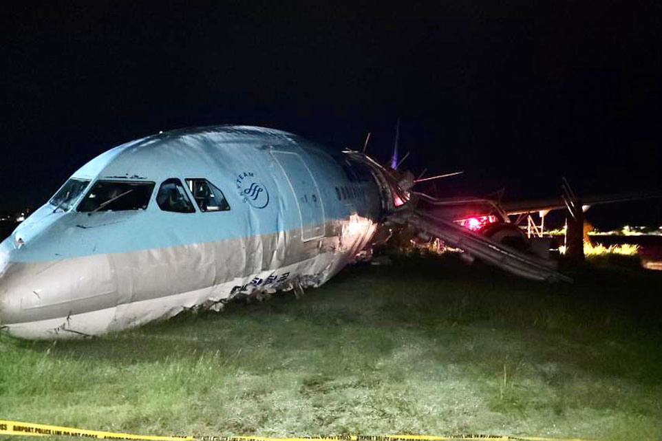
A Korean Air plane overshot a runway while landing at a central Philippines airport late Sunday (October 23) and caused a shutdown at one of the country"s busiest airports, the Associated Press reports.
The damaged plane remained stuck on Monday (October 24), causing dozens of flights to be canceled and Mactan-Cebu International Airport to shut down as the runway was deemed unusable.
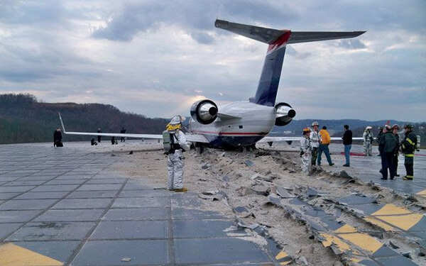
Republican vice-presidential nominee Mike Pence"s Boeing 737 at LaGuardia Airport.On Thursday, the campaign plane carrying Republican vice-presidential nominee Mike Pence skidded off the runway after landing at New York"s LaGuardia Airport.
The positive resolution to a potentially disastrous event can be attributed to the Engineered Material Arresting System or EMAS located at the end of the runway.
EMAS is made up of massive blocks of material that collapse as the wheels of an airplane roll over it, thereby sinking the plane into the runway and bringing it to a safe and gradual stop. The system is designed to be able to stop aircraft traveling at speeds up to 80 mph.
#PencePlane was overshot runway and wound up on #FAA mandated "arrestor bed," which stopped it in its tracks. #abc7ny pic.twitter.com/2LddxmUkfa- Josh Einiger (@JoshEiniger7) October 28, 2016

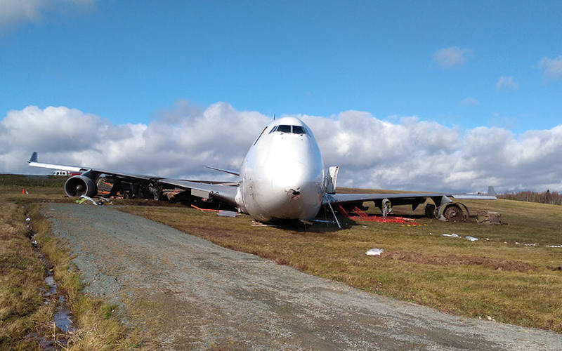
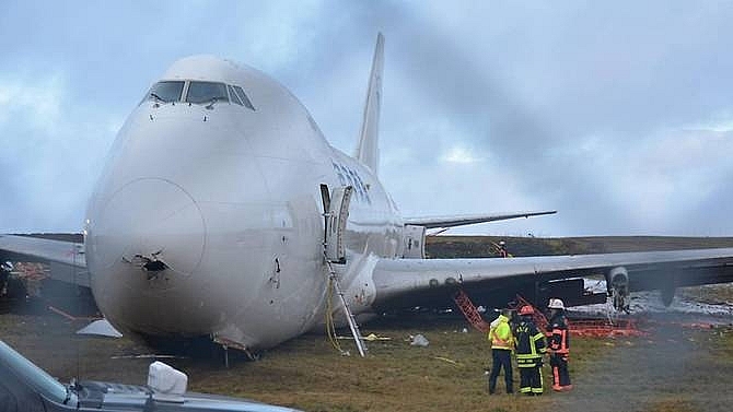
The Boeing 737 DHL cargo jet was attempting to land at Italy"s Bergamo airport after flying from Charles de Gaulle airport in Paris when the aircraft broke through the fence of the runway and ended up on the highway just after 4 a.m., said Italian aviation officials.


 8613371530291