
overshot water wheel design supplier

Water wheel design has evolved over time with some water wheels oriented vertically, some horizontally and some with elaborate pulleys and gears attached, but they are all designed to do the same function and that is too, “convert the linear motion of the moving water into a rotary motion which can be used to drive any piece of machinery connected to it via a rotating shaft”.
Early Waterwheel Design were quite primitive and simple machines consisting of a vertical wooden wheel with wooden blades or buckets fixed equally around their circumference all supported on a horizontal shaft with the force of the water flowing underneath it pushing the wheel in a tangential direction against the blades.
These vertical waterwheels were vastly superior to the earlier horizontal waterwheel design by the ancient Greeks and Egyptians, because they could operate more efficiently translating the hydrokinetic energy of the moving water into mechanical power. Pulleys and gearing was then attached to the waterwheel which allowed a change in direction of a rotating shaft from horizontal to vertical in order to operate millstones, saw wood, crush ore, stamping and cutting etc.
Most Waterwheels also known as Watermills or simply Water Wheels, are vertically mounted wheels rotating about a horizontal axle, and these types of waterwheels are classified by the way in which the water is applied to the wheel, relative to the wheel’s axle. As you may expect, waterwheels are relatively large machines which rotate at low angular speeds, and have a low efficiency, due to losses by friction and the incomplete filling of the buckets, etc.
The action of the water pushing against the wheels buckets or paddles develops torque on the axle but by directing the water at these paddles and buckets from different positions on the wheel the speed of rotation and its efficiency can be improved. The two most common types of waterwheel design is the “undershot waterwheel” and the “overshot waterwheel”.
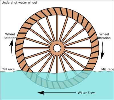
The Undershot Water Wheel Design, also known as a “stream wheel” was the most commonly used type of waterwheel designed by the ancient Greeks and Romans as it is the simplest, cheapest and easiest type of wheel to construct.
In this type of waterwheel design, the wheel is simply placed directly into a fast flowing river and supported from above. The motion of the water below creates a pushing action against the submerged paddles on the lower part of the wheel allowing it to rotate in one direction only relative to the direction of the flow of the water.
This type of waterwheel design is generally used in flat areas with no natural slope of the land or where the flow of water is sufficiently fast moving. Compared with the other waterwheel designs, this type of design is very inefficient, with as little as 20% of the waters potential energy being used to actually rotate the wheel. Also the waters energy is used only once to rotate the wheel, after which it flows away with the rest of the water.
Another disadvantage of the undershot water wheel is that it requires large quantities of water moving at speed. Therefore, undershot waterwheels are usually situated on the banks of rivers as smaller streams or brooks do not have enough potential energy in the moving water.
One way of improving the efficiency slightly of an undershot waterwheel is to divert a percentage off the water in the river along a narrow channel or duct so that 100% of the diverted water is used to rotate the wheel. In order to achieve this the undershot wheel has to be narrow and fit very accurately within the channel to prevent the water from escaping around the sides or by increasing either the number or size of the paddles.
The Overshot Water Wheel Design is the most common type of waterwheel design. The overshot waterwheel is more complicated in its construction and design than the previous undershot waterwheel as it uses buckets or small compartments to both catch and hold the water.
These buckets fill with water flowing onto the wheel through a penstock design above. The gravitational weight of the water in the full buckets causes the wheel to rotate around its central axis as the empty buckets on the other side of the wheel become lighter.
This type of water wheel uses gravity to improve output as well as the water itself, thus overshot waterwheels are much more efficient than undershot designs as almost all of the water and its weight is being used to produce output power. However as before, the waters energy is used only once to rotate the wheel, after which it flows away with the rest of the water.
Overshot waterwheels are suspended above a river or stream and are generally built on the sides of hills providing a water supply from above with a low head (the vertical distance between the water at the top and the river or stream below) of between 5-to-20 metres. A small dam or weir can be constructed and used to both channel and increase the speed of the water to the top of the wheel giving it more energy but it is the volume of water rather than its speed which helps rotate the wheel.
Generally, overshot waterwheels are built as large as possible to give the greatest possible head distance for the gravitational weight of the water to rotate the wheel. However, large diameter waterwheels are more complicated and expensive to construct due to the weight of the wheel and water.
When the individual buckets are filled with water, the gravitational weight of the water causes the wheel to rotate in the direction of the flow of water. As the angle of rotation gets nearer to the bottom of the wheel, the water inside the bucket empties out into the river or stream below, but the weight of the buckets rotating behind it causes the wheel to continue with its rotational speed.
Once the bucket is empty of water it continues around the rotating wheel until it gets back up to the top again ready to be filled with more water and the cycle repeats. One of the disadvantages of an overshot waterwheel design is that the water is only used once as it flows over the wheel.
The Pitchback Water Wheel Design is a variation on the previous overshot waterwheel as it also uses the gravitational weight of the water to help rotate the wheel, but it also uses the flow of the waste water below it to give an extra push. This type of waterwheel design uses a low head infeed system which provides the water near to the top of the wheel from a pentrough above.
Unlike the overshot waterwheel which channelled the water directly over the wheel causing it to rotate in the direction of the flow of the water, the pitchback waterwheel feeds the water vertically downwards through a funnel and into the bucket below causing the wheel to rotate in the opposite direction to the flow of the water above.
Just like the previous overshot waterwheel, the gravitational weight of the water in the buckets causes the wheel to rotate but in an anti-clockwise direction. As the angle of rotation nears the bottom of the wheel, the water trapped inside the buckets empties out below. As the empty bucket is attached to the wheel, it continues rotating with the wheel as before until it gets back up to the top again ready to be filled with more water and the cycle repeats.
The difference this time is that the waste water emptied out of the rotating bucket flows away in the direction of the rotating wheel (as it has nowhere else to go), similar to the undershot waterwheel principal. Thus the main advantage of the pitchback waterwheel is that it uses the energy of the water twice, once from above and once from below to rotate the wheel around its central axis.
The result is that the efficiency of the waterwheel design is greatly increased to over 80% of the waters energy as it is driven by both the gravitaional weight of the incoming water and by the force or pressure of water directed into the buckets from above, as well as the flow of the waste water below pushing against the buckets. The disadvantage though of an pitchback waterwheel is that it needs a slightly more complex water supply arrangement directly above the wheel with chutes and pentroughs.
The Breastshot Water Wheel Design is another vertically-mounted waterwheel design where the water enters the buckets about half way up at axle height, or just above it, and then flows out at the bottom in the direction of the wheels rotation. Generally, the breastshot waterwheel is used in situations were the head of water is insufficient to power an overshot or pitchback waterwheel design from above.
The disadvantage here is that the gravitational weight of the water is only used for about one quarter of the rotation unlike previously which was for half the rotation. To overcome this low head height, the waterwheels buckets are made wider to extract the required amount of potential energy from the water.
Breastshot waterwheels use about the same gravitational weight of the water to rotate the wheel but as the head height of the water is around half that of a typical overshot waterwheel, the buckets are a lot wider than previous waterwheel designs to increase the volume of the water caught in the buckets.
The disadvantage of this type of design is an increase in the width and weight of the water being carried by each bucket. As with the pitchback design, the breastshot wheel uses the energy of the water twice as the waterwheel is designed to sit in the water allowing the waste water to help in the rotation of the wheel as it flows away down stream.
Historically water wheels have been used for milling flour, cereals and other such mechanical tasks. But water wheels can also be used for the generation of electricity, called a Hydro Power system.
By connecting an electrical generator to the waterwheels rotating shaft, either directly or indirectly using drive belts and pulleys, waterwheels can be used to generate power continuously 24 hours a day unlike solar energy. If the waterwheel is designed correctly, a small or “micro” hydroelectric system can produce enough electricity to power lighting and/or electrical appliances in an average home.
Look for Water wheel Generators designed to produce its optimum output at relatively low speeds. For small projects, a small DC motor can be used as a low-speed generator or an automotive alternator but these are designed to work at much higher speeds so some form of gearing may be required. A wind turbine generator makes an ideal waterwheel generator as it is designed for low speed, high output operation.
If there is a fairly fast flowing river or stream near to your home or garden which you can use, then a small scale hydro power system may be a better alternative to other forms of renewable energy sources such as “Wind Energy” or “Solar Energy” as it has a lot less visual impact. Also just like wind and solar energy, with a grid-connected small scale waterwheel designed generating system connected to the local utility grid, any electricity you generate but don’t use can be sold back to the electricity company.
In the next tutorial about Hydro Energy, we will look at the different types of turbines available which we could attach to our waterwheel design for hydro power generation. For more information about Waterwheel Design and how to generate your own electricity using the power of water, or obtain more hydro energy information about the various waterwheel designs available, or to explore the advantages and disadvantages of hydro energy, then Click Here to order your copy from Amazon today about the principles and construction of waterwheels which can be used for generating electricity.

Waterwheel Factory shares it"s knowledge about waterwheels and displays the inherent beauty of a moving waterwheel. Explore; water wheels in history; waterwheel calculations; waterwheels for energy, and gristmill restorations. Explore the many ways you can enjoy having your own waterwheel for landscape decoration or any project you may have in mind.Sit back, relax, and enjoy the many exciting photo’s and options we offer.

The Poncelet Wheel, pictured above, offers a curved bucket with its lip angled tangentially to eliminate the impact of water to near zero. Developed in 1824, this design flourished for over 10 years. Now forgotten for more than a century, this ingenious design, more than any other, pointed the way to the great changes in "water engines" that were to occur in the late 1800’s.
The Poncelet was a graceful, efficient, undershot wheel, unlike any other before it. Now, the Poncelet wheel usually receives but slight mention in modern engineering textbooks, often only a short paragraph with few details. It deserves much more, for it was the first wheel designed to meet the advanced principles of hydraulic physics, thus setting a precedent for all later developers of waterpower.
It is important to understand the environment in which Jean Victor Poncelet developed his unique design. In the 1820’s Britain and Europe were in the midst of the great industrial revolution. The steam engine was a generation away from taking the leading role in powering industry in France. There was scarcely a good hydro site in England or Europe that had not been harnessed. Many of the streams had mills so crowded together that one could travel for long distances without getting out of sight of a water wheel. Every inch of head was precious, and every gallon of flow was treasured. The government of France and others offered large prizes and great honors to designers of more efficient water wheels. Many of the best minds of the day were engaged in seeking additional energy for their burgeoning industry.
It was estimated that there were more 60,000 operating water wheels in France in the mid-1820’s. Many of the streams in the industrial areas of France were located in rather flat topography. Jean V. Poncelet studied the widely used undershot wheel, the least efficient of all water wheels, and developed a new design that more than doubled its efficiency. His new design met with instant success. The mill operators were well acquainted with the limitations of their old undershot wheels and immediately recognized the superiority of the Poncelet design. Several manufacturers erected new wheels of Poncelet"s design immediately, without waiting for years of testing by others. The French Academy of Science awarded Poncelet its "Prix de Mecanique". In the next few years, many other Poncelet wheels were installed chiefly in France and Germany.
What made the new Poncelet design so much more efficient than the previous designs? How did this new wheel extract more than double the power from the same stream? The older undershot wheels presented a flat blade for the incoming water to impact. Part of energy from this impact became heat, a totally unnecessary byproduct in a water wheel. Also, the rim speed of the old wheels was equal to one-half of the velocity of the incoming water; therefore, they only slowed the water movement by half, allowing half of the velocity to pass through unchecked. These losses resulted in most of the old undershot wheels developing less than 30% efficiency.
The Poncelet design, on the other hand, presented a curved blade with its lip angled tangentially to the incoming water so as to eliminate the impact to near zero. The blades of this new wheel also receded before the incoming water at one half of its velocity. In the Poncelet wheel, the water climbed up the curved incline, cresting about the top of the blade after entry and receding to the lip in another 15-degree devoid of practically all of its forward momentum thus transferring substantially all of its energy to the wheel. The water was held in the wheel by a breastwork extending 15" each side of bottom dead center. This gave the Poncelet a potential efficiency of 100%, with an actual realized efficiency of 60% to 70%.
As an example, a 16-foot diameter Poncelet wheel operating on a 4-foot head receives the water at a velocity of 16 feet per second. In 1/2 of a second and in 4 feet of travel, it substantially stops the water without impact and simply drops it in the tailrace devoid of its forward velocity. This was the first design in which the flow of water within the wheel was considered important. A correctly timed Poncelet wheel is a graceful and efficient machine. It will work as well today as it did in the 1820s and 1830s. It is probably the best wheel to employ on heads of 6 feet or less, particularly where the flow rate is subject to wide variations during a cycle of seasons. On wide streams where the head will vary but little, this wheel can be made to accommodate a 300% to 400% variation in flow rate with little effect on its efficiency. If one has a hydro site with as little as 2 feet of head and with a sufficient flow of water, a Poncelet designed for this combination may be the most practical wheel available.
Why were they all but forgotten after 1850? Close observation will reveal that what one has in the Poncelet design is a large turbine. Note its close blade resemblance to the everyday common water pump we have today.

Freeflow69 are happy to design water wheels for any site installation, just let us have the site details, water flow and head and we can give advice on the wheel required. Where a water wheel is not the appropriate equipment for a specific location, we can advise on other products and provide the installation design. For example; Cross Flow Turbine, Pelton Wheel or Axial Flow Turbine.
Here we have a breast shot wheel for a "run of river" installation (2.7metre diameter x 2 metre wide).The project Involved the design, manufacture and commissioning of this medium head Zuppinger enclosed type water wheel, It is now installed and running.

The 4.1m diameter waterwheel is positioned in an existing water supply in one of the old wheel pits of the former gunpowder works, next to The Langdale Estate’s original turbine house which generated electricity for the estate in the 19th century.
The spokes, rims and buckets were all fabricated from 3mm pre-galvanised sheet finished with polyester powder coating. These lightweight components were easily and rapidly assembled using stainless steel nuts and bolts without the need for welding or any special tools on site. Only the wheel hub required welding and this was undertaken at our factory.
Delivery to site as a flat pack kit enabled it to be installed without the need for a large crane which would have been unable to travel down the narrow road to the site. This unique feature allows our overshot wheels to be installed in remote locations where there is restricted access.
Tests undertaken with Dr Paddy Quinlan of the University of Cumbria show that high mechanical efficiencies can be achieved from our overshot wheels. A water-to-wire efficiency of 65% was expected but the tests showed it is over 75%.
The waterwheel was funded through the University of Cumbria’s Renewable Energy Test and Education Centre (RETEC) with funding from Britain’s Energy Coast in partnership with the Nuclear Decommissioning Authority.
Back in 1947, Popular Science printed a five-part article by C.D. Bassett that very concisely sketched out every step necessary for the establishment of a small water-power plant on a farm or homestead. That information is still just as valuable today for many of MOTHER’s readers as it was 30 years ago . . . and that’s why THE MOTHER EARTH NEWS asked for — and received — permission to reprint the whole series as a two-part article in MOTHER NOs. 13 and 14. The Popular Science material was also included — by permission — in THE MOTHER EARTH NEWS Handbook of Homemade Power.
If any of the terms or ideas in the accompanying article are unfamiliar to you, then, you have three choices: [1] You can trot on down to your local library and exhume the old, original C.D. Bassett articles from the 1947 issues of Popular Science, [2] you can order out MOTHER NOS. 13 and 14 at $2.00 apiece from the ad on pages 114-115 of this issue, or[3] you can get your own copy – $1.95 plus 75¢ shipping and handling — of The Handbook of Homemade Power by using the MOTHER’s Bookshelf ad on pages 174 -177 of this issue. Any way you go about it, you’re going to learn all you need to know to lay out, install, and operate your own water-power system. All you’ll need to add to this information is a free-flowing stream . . . and you’re in business.
One final note: The following article describes a homemade overshot water wheel set up to do only one thing . . . pump water from a spring to a set of farm buildings 100 feet above. If you’re more interested in learning how to use the same kind of wheel to generate electricity, see the article, schematic drawing, and photographs of Thomas Oates’ water-wheel powered DC electrical system in MOTHER NO. 24. That piece was also reprinted in The Handbook of Homemade Power. — The Editors.
One very successful example of this “back to basics” trend is the water wheel-powered water pump now in operation on the Robert Wooding farm near Halifax, Virginia. The pump-powered by a home designed and home-built 6 1/2-foot, steel water wheel which, in turn, is spun by water from a stream on the family farm shoves 1,440 gallons of pure spring water 100 feet uphill every 24 hours. And, since the system was set up, it hasn’t cost the Woodings anything for its tireless round-the-clock operation . . . except a few cents for lubrication.
“There are three things I especially like about my wheel,” says Bob blooding. “One, unlike the hydraulic ram pumps featured several times in MOTHER, it doesn’t use gallons and gallons of our drinking water just to pump a few gallons up the hill. Two, the overshot design of our wheel makes very efficient use of the small stream we tap for power. And, three, there’s not a whole lot of banjo work to a rig like this once you’ve got it going. We spent a little time and money setting our system up, to be sure, but it’s been practically maintenance-free ever since. About all we do is give its bearings a shot of grease two or three times a year.”
The Woodings were fortunate enough to have a picturesque stream on their property (the first and most obvious requirement for any water-power system!) . . . but that’s as far as their luck went. At no single spot along the creek was there enough “fall” to turn the 6 1/2-foot overshot wheel that Bob figured on installing.
Fall, as the name implies, is the amount of vertical distance that running water drops as it moves down a stream (if there were no fall at all, the water — obviously — wouldn’t run and the stream wouldn’t be a stream . . . it would be a slough or a lake).
The ideal location, of course, for an overshot water wheel (which must be positioned in a stream at a spot where the water abruptly drops at least as far as the wheel is tall) is a natural rapids or waterfall. If, like the Woodings, you find yourself working with a stream that has no such abrupt natural drop, however, you’ll have to do what the Woodings did: Build your own man-made waterfall . . . which, as we all know, is commonly called a dam.
(NOTE: The reprinted series of five articles from Popular Science mentioned at the beginning of this piece contains everything you need to know to calculate the flow and call of a stream, design several kinds of dams, build and install an overshot wheel, and otherwise fabricate and operate a farm- or homestead-sized water-power system. — The Editors.)
“We needed about a seven-foot fall for our 6 1/2-foot-tall wheel,” Bob blooding remembers, “so we built a three-foot-tall dam . . . and then flumed the water from the top of that dam to a spot 120 feet further downstream where the creek’s banks were an additional tour feet lower. The dam’s height of three feet plus the additional four feet of drop we picked up by running our flume that tar added up to the seven feet of fall, or head, that we needed for our wheel.”
The Woodings’ flume is a combination of approximately 85 feet of four-inch aluminum pipe feeding into an additional 46 1/2 feet of wooden trough measuring six inches deep by six inches wide. (The aluminum pipe, which extends about a foot and a half into the trough, can be lifted out and set into a curved metal deflector which routes its water back into the stream whenever the Woodings want to stop the wheel.)
Traditional flumes for homestead water wheels, of course, were of all-wood construction. But Bob Wooding decided to use rot-free, corrosion-free aluminum pipe for the first two-thirds of his wheel’s feeder line, where the flume had to extend into the water and then run underground. The pipe’s inlet is covered with a screen to keep the line from becoming clogged with misguided leaves, turtles, and crawfish. Care was also taken to position the opposite (wooden) end of the flume so that its discharge of water would hit the exact top-center of the overshot wheel.
Although the blooding family’s water system for their house, stables, and swimming pool is powered by the stream on their farm . . . the actual water which flows through that system comes from a clear, cool, pure spring. This spring, too (just like their dam), is located about 120 feet from the overshot wheel and pump that is the heart of the whole hookup. So, in addition to the flume which carries the “driving” water from the dam to the wheel, another one-inch pipe was laid to carry the “driven” water from the spring to the pump that is installed next to (and driven by) the wheel.
Luckily for the Woodings, the spring water’s temperature stays 52 degrees Fahrenheit year round. Merely by laying this feeder pipe so that it has a continuous slight grade from the spring down to the pump a few feet below, then, the family has been able to keep their water supply from freezing in the winter without going to the trouble of burying the pipe below the frost line.
When you buy a manufactured water wheel, a large portion of the purchase price goes to pay for the equipment’s design. It follows, then, that you can save yourself a sizable chunk of cash by working up the specifications for your own wheel . . . and that’s exactly what Bob Wooding did.
Actually, this isn’t as difficult as you might think. To extract maximum power from any given flow of water with an overshot wheel is largely a matter of calculating the proper depth and angle of the buckets placed around the wheel’s rim (ideally, each bucket must be completely filled at top center and then carry its load of water without spilling a drop until just the instant it passed bottom center . . . but anything even remotely approaching this ideal will handle the job satisfactorily in most homestead applications).
(EDITORS’ NOTE: If you scale up the drawings shown here and use them to construct a wheel ranging anywhere from two feet up to 20 feet in diameter — and if you work carefully and in a craftsman-like manner — the chances are good that your finished wheel will work well enough to make you pretty dang proud of yourself. If you really want to go for the finer points of maximum efficiency, however, you can work from the more detailed dimensions and angles given in the full-page drawing of an overshot wheel on page 31 of MOTHER N0. 14.)
After drawing up his design (complete with “dribble” hole in the bottom of each bucket, so that the wheel is self-draining when not in use!), Bob had the individual parts for his water wheel prefabbed by the Carolina Steel Company in Greensboro, North Carolina. A Richmond, Virginia representative for the firm says that the 3/16 inch steel plate used in the 980-pound assembly’s 37 eight-by-twelve-inch buckets, its five-inch-wide rim, and its one-foot-wide sole plate would currently cost about $130. You can add on another $70 for burning, forming, and welding the metal. (These prices, of course, will vary in different parts of the country and — as time goes on — are sure to escalate right along with the price of everything else.)
The hubs for the Wooding wheel were pretty much “Chinese copied” from the hubs manufactured years ago by the now-defunct Fitz Water Wheel Company of Hanover, Pennsylvania. Bob had them cast at a local foundry from a wooden pattern that he made himself, and the materials and labor for the raw castings set him back only $25. A nearby machine shop then bored out the hubs on a lathe, cut keyways into the bores, and made up the pair (each half of the set contains six 3/8 inch by 2 inch spokes) of spokes for the wheel . . . all for only $60 complete.
Once he had all the components for his wheel prefabbed and in hand, there was nothing for Bob Wooding to do but assemble the power unit. “I used calipers to measure and remeasure the spaces around the rim for my buckets until I had them exact to the width of a pencil mark,” Bob says. “Then I tacked the buckets in place all the way around and rechecked everything before I finally welded them in permanently. If you try to finish-weld each one as you go without tacking everything together first, you know, you can get off kilter and warp the whole wheel.”
Every one of the six “ears”, or extensions, on each of the two hubs has a recessed area 3/8 inches deep by two inches wide by four inches long on its inside surface for a spoke to set into. This end of each spoke is held firmly in place with two 7/16 inch galvanized bolts, nuts, and lock washers. The other ends of the spokes are welded to the outside faces of the wheel’s rim . . . as you can see in one of the accompanying photos.
It should also be pointed out that the distance (16 inches) between the two hubs is four inches wider than the distance (12 inches) across the buckets on the rim. This “dish” effect — so typical of the Fitz wheels of years ago — adds a great deal of strength to the completed wheel . . . without adding any additional weight.
The finished wheel was hoisted with a front-end loader, hauled to the foundation that had been poured for it, and gently eased down until the pillow block bearings on its two-inch steel shaft could be bolted into place. A few small pieces of metal were then welded into some of the buckets to balance the completed assembly, and the whole wheel was given a primer coat of zinc chromate and a finish coat of black enamel.
As water pours down over one side of the mounted wheel and turns it, the spinning of the wheel is converted to an up-and-down pumping motion by an eccentric arm attached to the assembly’s two-inch-thick main shaft. This “arm”, to be truthful, is not really an arm at all . . . but simply a spot one and a half inches off center on the face of a 15-inch gear salvaged from a local junkyard. The spot has been drilled and tapped to accept a threaded mounting pin for the lower end of a long white oak connecting rod.
As the water wheel’s main shaft rotates, then, the 15-inch gear attached to it also rotates smoothly. This causes the eccentric pin fastened to the face of the gear to revolve around and around in a three-inch arc. Which, in turn, causes the guided white oak connecting rod that rides the pin to pump up and down with a three-inch stroke.
The upper end of the connecting rod (think of it as the hand holding the handle of an old-fashioned “armstrong” water pump) is bolted to a cross-arm that runs across the top of a reservoir and is secured to a red cedar post on the other side so that it can hinge up and down. And in the middle of that cross-arm — just off center in favor of the water wheel — is attached a cylinder rod which runs down to a cylinder pump that is firmly bolted to the bottom of the reservoir.
And that’s all there is to the Wooding stream-run, spring-fed water system. Water from the spring 120 feet away runs a couple of feet downhill to fill the cement reservoir. At the same time, a great deal more water from the dam — also about 120 feet away but in a slightly different direction — flows through the flume and pours down over one side of the 6 1/2-foot water wheel, causing it to turn. And, as the wheel turns, the pump in the reservoir pumps . . . which forces the fresh spring water 100 feet uphill (through a line buried beneath the frost line) to a 500-gallon storage tank which stands near the blooding house. And, from that tank, the spring water is then gravity-fed to the house, stables, and swimming pool on the blooding property.
And there’s something rather nice about the whole arrangement. The “splash-splosh” of the water wheel is far more relaxing and natural than any huffing-puffing engine . . . and a lot less expensive to operate year in, year out than any quiet but increasingly costly electric motor. Every bit of technology used in the Wooding setup, of course, has been around a long, long time . . . and a lot of other farmsteads in the country could put a variation of the same idea into use right now.

A water wheel is a machine for converting the energy of flowing or falling water into useful forms of power, often in a watermill. A water wheel consists of a wheel (usually constructed from wood or metal), with a number of blades or buckets arranged on the outside rim forming the driving car. Water wheels were still in commercial use well into the 20th century but they are no longer in common use. Uses included milling flour in gristmills, grinding wood into pulp for papermaking, hammering wrought iron, machining, ore crushing and pounding fibre for use in the manufacture of cloth.
Some water wheels are fed by water from a mill pond, which is formed when a flowing stream is dammed. A channel for the water flowing to or from a water wheel is called a mill race. The race bringing water from the mill pond to the water wheel is a headrace; the one carrying water after it has left the wheel is commonly referred to as a tailrace.
Waterwheels were used for various purposes from agriculture to metallurgy in ancient civilizations spanning the Hellenistic Greek world, Rome, China and India. Waterwheels saw continued use in the Post-classical age, like the Middle Ages of Europe and the Islamic Golden Age, but also elsewhere. In the mid to late 18th century John Smeaton"s scientific investigation of the water wheel led to significant increases in efficiency supplying much needed power for the Industrial Revolution.turbine, developed by Benoît Fourneyron, beginning with his first model in 1827.elevations, that exceed the capability of practical-sized waterwheels.
The main difficulty of water wheels is their dependence on flowing water, which limits where they can be located. Modern hydroelectric dams can be viewed as the descendants of the water wheel, as they too take advantage of the movement of water downhill.
Overshot and backshot water wheels are typically used where the available height difference is more than a couple of meters. Breastshot wheels are more suited to large flows with a moderate head. Undershot and stream wheel use large flows at little or no head.
There is often an associated millpond, a reservoir for storing water and hence energy until it is needed. Larger heads store more gravitational potential energy for the same amount of water so the reservoirs for overshot and backshot wheels tend to be smaller than for breast shot wheels.
Overshot and pitchback water wheels are suitable where there is a small stream with a height difference of more than 2 metres (6.5 ft), often in association with a small reservoir. Breastshot and undershot wheels can be used on rivers or high volume flows with large reservoirs.
Stream wheels are cheaper and simpler to build and have less of an environmental impact, than other types of wheels. They do not constitute a major change of the river. Their disadvantages are their low efficiency, which means that they generate less power and can only be used where the flow rate is sufficient. A typical flat board undershot wheel uses about 20 percent of the energy in the flow of water striking the wheel as measured by English civil engineer John Smeaton in the 18th century.
Stream wheels mounted on floating platforms are often referred to as hip wheels and the mill as a ship mill. They were sometimes mounted immediately downstream from bridges where the flow restriction of the bridge piers increased the speed of the current.
An undershot wheel is a vertically mounted water wheel with a horizontal axle that is rotated by the water from a low weir striking the wheel in the bottom quarter. Most of the energy gain is from the movement of the water and comparatively little from the head. They are similar in operation and design to stream wheels.
The word breastshot is used in a variety of ways. Some authors restrict the term to wheels where the water enters at about the 10 o’clock position, others 9 o’clock, and others for a range of heights.
The small clearance between the wheel and the masonry requires that a breastshot wheel has a good trash rack ("screen" in British English) to prevent debris from jamming between the wheel and the apron and potentially causing serious damage.
Breastshot wheels are less efficient than overshot and backshot wheels but they can handle high flow rates and consequently high power. They are preferred for steady, high-volume flows such as are found on the Fall Line of the North American East Coast. Breastshot wheels are the most common type in the United States of America
A vertically mounted water wheel that is rotated by water entering buckets just past the top of the wheel is said to be overshot. The term is sometimes, erroneously, applied to backshot wheels, where the water goes down behind the wheel.
A typical overshot wheel has the water channeled to the wheel at the top and slightly beyond the axle. The water collects in the buckets on that side of the wheel, making it heavier than the other "empty" side. The weight turns the wheel, and the water flows out into the tail-water when the wheel rotates enough to invert the buckets. The overshot design is very efficient, it can achieve 90%,
Nearly all of the energy is gained from the weight of water lowered to the tailrace although a small contribution may be made by the kinetic energy of the water entering the wheel. They are suited to larger heads than the other type of wheel so they are ideally suited to hilly countries. However even the largest water wheel, the Laxey Wheel in the Isle of Man, only utilises a head of around 30 m (100 ft). The world"s largest head turbines, Bieudron Hydroelectric Power Station in Switzerland, utilise about 1,869 m (6,132 ft).
Overshot wheels require a large head compared to other types of wheel which usually means significant investment in constructing the headrace. Sometimes the final approach of the water to the wheel is along a flume or penstock, which can be lengthy.
A backshot wheel (also called pitchback) is a variety of overshot wheel where the water is introduced just before the summit of the wheel. In many situations, it has the advantage that the bottom of the wheel is moving in the same direction as the water in the tailrace which makes it more efficient. It also performs better than an overshot wheel in flood conditions when the water level may submerge the bottom of the wheel. It will continue to rotate until the water in the wheel pit rises quite high on the wheel. This makes the technique particularly suitable for streams that experience significant variations in flow and reduces the size, complexity, and hence cost of the tailrace.
The direction of rotation of a backshot wheel is the same as that of a breastshot wheel but in other respects, it is very similar to the overshot wheel. See below.
Some wheels are overshot at the top and backshot at the bottom thereby potentially combining the best features of both types. The photograph shows an example at Finch Foundry in Devon, UK. The head race is the overhead timber structure and a branch to the left supplies water to the wheel. The water exits from under the wheel back into the stream.
A special type of overshot/backshot wheel is the reversible water wheel. This has two sets of blades or buckets running in opposite directions so that it can turn in either direction depending on which side the water is directed. Reversible wheels were used in the mining industry in order to power various means of ore conveyance. By changing the direction of the wheel, barrels or baskets of ore could be lifted up or lowered down a shaft or inclined plane. There was usually a cable drum or a chain basket on the axle of the wheel. It is essential that the wheel have braking equipment to be able to stop the wheel (known as a braking wheel). The oldest known drawing of a reversible water wheel was by Georgius Agricola and dates to 1556.
The earliest waterwheel working like a lever was described by Zhuangzi in the late Warring States period (476-221 BC). It says that the waterwheel was invented by Zigong, a disciple of Confucius in the 5th century BC.Chinese of the Eastern Han Dynasty were using water wheels to crush grain in mills and to power the piston-bellows in forging iron ore into cast iron.
In the text known as the Xin Lun written by Huan Tan about 20 AD (during the usurpation of Wang Mang), it states that the legendary mythological king known as Fu Xi was the one responsible for the pestle and mortar, which evolved into the tilt-hammer and then trip hammer device (see trip hammer). Although the author speaks of the mythological Fu Xi, a passage of his writing gives hint that the water wheel was in widespread use by the 1st century AD in China (Wade-Giles spelling):
Fu Hsi invented the pestle and mortar, which is so useful, and later on it was cleverly improved in such a way that the whole weight of the body could be used for treading on the tilt-hammer (tui), thus increasing the efficiency ten times. Afterwards the power of animals—donkeys, mules, oxen, and horses—was applied by means of machinery, and water-power too used for pounding, so that the benefit was increased a hundredfold.
In the year 31 AD, the engineer and Prefect of Nanyang, Du Shi (d. 38), applied a complex use of the water wheel and machinery to power the bellows of the blast furnace to create cast iron. Du Shi is mentioned briefly in the Hou Han Shu) as follows (in Wade-Giles spelling):
In the seventh year of the Chien-Wu reign period (31 AD) Tu Shih was posted to be Prefect of Nanyang. He was a generous man and his policies were peaceful; he destroyed evil-doers and established the dignity (of his office). Good at planning, he loved the common people and wished to save their labor. He invented a water-power reciprocator (shui phai) for the casting of (iron) agricultural implements. Those who smelted and cast already had the push-bellows to blow up their charcoal fires, and now they were instructed to use the rushing of the water (chi shui) to operate it ... Thus the people got great benefit for little labor. They found the "water(-powered) bellows" convenient and adopted it widely.
Water wheels in China found practical uses such as this, as well as extraordinary use. The Chinese inventor Zhang Heng (78–139) was the first in history to apply motive power in rotating the astronomical instrument of an armillary sphere, by use of a water wheel.mechanical engineer Ma Jun (c. 200–265) from Cao Wei once used a water wheel to power and operate a large mechanical puppet theater for the Emperor Ming of Wei (r. 226–239).
The ancient Greeks invented the waterwheel independently and used it in nearly all of the forms and functions described above, including its application for watermilling.Hellenistic period between the 3rd and 1st century BC.
The compartmented water wheel comes in two basic forms, the wheel with compartmented body (Latin tympanum) and the wheel with compartmented rim or a rim with separate, attached containers.sakia gear.
The earliest literary reference to a water-driven, compartmented wheel appears in the technical treatise Pneumatica (chap. 61) of the Greek engineer Philo of Byzantium (ca. 280−220 BC).Parasceuastica (91.43−44), Philo advises the use of such wheels for submerging siege mines as a defensive measure against enemy sapping.dry docks in Alexandria under the reign of Ptolemy IV (221−205 BC).papyri of the 3rd to 2nd century BC mention the use of these wheels, but don"t give further details.Ancient Near East before Alexander"s conquest can be deduced from its pronounced absence from the otherwise rich oriental iconography on irrigation practices.
The earliest depiction of a compartmented wheel is from a tomb painting in Ptolemaic Egypt which dates to the 2nd century BC. It shows a pair of yoked oxen driving the wheel via a sakia gear, which is here for the first time attested, too.Museum of Alexandria, at the time the most active Greek research center, may have been involved in its invention.Alexandrian War in 48 BC tells of how Caesar"s enemies employed geared waterwheels to pour sea water from elevated places on the position of the trapped Romans.
Around 300 AD, the noria was finally introduced when the wooden compartments were replaced with inexpensive ceramic pots that were tied to the outside of an open-framed wheel.
The Romans used waterwheels extensively in mining projects, with enormous Roman-era waterwheels found in places like modern-day Spain. They were reverse overshot water-wheels designed for dewatering deep underground mines.Vitruvius, including the reverse overshot water-wheel and the Archimedean screw. Many were found during modern mining at the copper mines at Rio Tinto in Spain, one system involving 16 such wheels stacked above one another so as to lift water about 80 feet from the mine sump. Part of such a wheel was found at Dolaucothi, a Roman gold mine in south Wales in the 1930s when the mine was briefly re-opened. It was found about 160 feet below the surface, so must have been part of a similar sequence as that discovered at Rio Tinto. It has recently been carbon dated to about 90 AD, and since the wood from which it was made is much older than the deep mine, it is likely that the deep workings were in operation perhaps 30–50 years after. It is clear from these examples of drainage wheels found in sealed underground galleries in widely separated locations that building water wheels was well within their capabilities, and such verticals water wheels commonly used for industrial purposes.
Taking indirect evidence into account from the work of the Greek technician Apollonius of Perge, the British historian of technology M.J.T. Lewis dates the appearance of the vertical-axle watermill to the early 3rd century BC, and the horizontal-axle watermill to around 240 BC, with Byzantium and Alexandria as the assigned places of invention.Strabon (ca. 64 BC–AD 24) to have existed sometime before 71 BC in the palace of the Pontian king Mithradates VI Eupator, but its exact construction cannot be gleaned from the text (XII, 3, 30 C 556).
The first clear description of a geared watermill offers the late 1st century BC Roman architect Vitruvius who tells of the sakia gearing system as being applied to a watermill.
About the same time, the overshot wheel appears for the first time in a poem by Antipater of Thessalonica, which praises it as a labour-saving device (IX, 418.4–6).Lucretius (ca. 99–55 BC) who likens the rotation of the waterwheel to the motion of the stars on the firmament (V 516).central Gaul.Barbegal watermill complex a series of sixteen overshot wheels was fed by an artificial aqueduct, a proto-industrial grain factory which has been referred to as "the greatest known concentration of mechanical power in the ancient world".
In Roman North Africa, several installations from around 300 AD were found where vertical-axle waterwheels fitted with angled blades were installed at the bottom of a water-filled, circular shaft. The water from the mill-race which entered tangentially the pit created a swirling water column that made the fully submerged wheel act like true water turbines, the earliest known to date.
Apart from its use in milling and water-raising, ancient engineers applied the paddled waterwheel for automatons and in navigation. Vitruvius (X 9.5–7) describes multi-geared paddle wheels working as a ship odometer, the earliest of its kind. The first mention of paddle wheels as a means of propulsion comes from the 4th–5th century military treatise
Ancient water-wheel technology continued unabated in the early medieval period where the appearance of new documentary genres such as legal codes, monastic charters, but also hagiography was accompanied with a sharp increase in references to watermills and wheels.
The earliest excavated water wheel driven by tidal power was the Nendrum Monastery mill in Northern Ireland which has been dated to 787, although a possible earlier mill dates to 619. Tide mills became common in estuaries with a good tidal range in both Europe and America generally using undershot wheels.
Cistercian monasteries, in particular, made extensive use of water wheels to power watermills of many kinds. An early example of a very large water wheel is the still extant wheel at the early 13th century Real Monasterio de Nuestra Senora de Rueda, a Cistercian monastery in the Aragon region of Spain. Grist mills (for corn) were undoubtedly the most common, but there were also sawmills, fulling mills and mills to fulfil many other labour-intensive tasks. The water wheel remained competitive with the steam engine well into the Industrial Revolution. At around the 8th to 10th century, a number of irrigation technologies were brought into Spain and thus introduced to Europe. One of those technologies is the Noria, which is basically a wheel fitted with buckets on the peripherals for lifting water. It is similar to the undershot water wheel mentioned later in this article. It allowed peasants to power watermills more efficiently. According to Thomas Glick"s book, Irrigation and Society in Medieval Valencia, the Noria probably originated from somewhere in Persia. It has been used for centuries before the technology was brought into Spain by Arabs who had adopted it from the Romans. Thus the distribution of the Noria in the Iberian peninsula "conforms to the area of stabilized Islamic settlement".Spaniards, the technology spread to the New World in Mexico and South America following Spanish expansion
The type of water wheel selected was dependent upon the location. Generally if only small volumes of water and high waterfalls were available a millwright would choose to use an overshot wheel. The decision was influenced by the fact that the buckets could catch and use even a small volume of water.
Harnessing water-power enabled gains in agricultural productivity, food surpluses and the large scale urbanization starting in the 11th century. The usefulness of water power motivated European experiments with other power sources, such as wind and tidal mills.canals, put Europe on a hydraulically focused path, for instance water supply and irrigation technology was combined to modify supply power of the wheel.feudal state.
The water mill was used for grinding grain, producing flour for bread, malt for beer, or coarse meal for porridge.fulling mill, which was used for cloth making. The trip hammer was also used for making wrought iron and for working iron into useful shapes, an activity that was otherwise labour-intensive. The water wheel was also used in papermaking, beating material to a pulp. In the 13th century water mills used for hammering throughout Europe improved the productivity of early steel manufacturing. Along with the mastery of gunpowder, waterpower provided European countries worldwide military leadership from the 15th century.
Millwrights distinguished between the two forces, impulse and weight, at work in water wheels long before 18th-century Europe. Fitzherbert, a 16th-century agricultural writer, wrote "druieth the wheel as well as with the weight of the water as with strengthe [impulse]".Leonardo da Vinci also discussed water power, noting "the blow [of the water] is not weight, but excites a power of weight, almost equal to its own power".laws of force. Evangelista Torricelli"s work on water wheels used an analysis of Galileo"s work on falling bodies, that the velocity of a water sprouting from an orifice under its head was exactly equivalent to the velocity a drop of water acquired in falling freely from the same height.
The water wheel was a driving force behind the earliest stages of industrialization in Britain. Water-powered reciprocating devices were used in trip hammers and blast furnace bellows. Richard Arkwright"s water frame was powered by a water wheel.
The most powerful water wheel built in the United Kingdom was the 100 hp Quarry Bank Mill water wheel near Manchester. A high breastshot design, it was retired in 1904 and replaced with several turbines. It has now been restored and is a museum open to the public.
The biggest working water wheel in mainland Britain has a diameter of 15.4 m (51 ft) and was built by the De Winton company of Caernarfon. It is located within the Dinorwic workshops of the National Slate Museum in Llanberis, North Wales.
The largest working water wheel in the world is the Laxey Wheel (also known as Lady Isabella) in the village of Laxey, Isle of Man. It is 72 feet 6 inches (22.10 m) in diameter and 6 feet (1.83 m) wide and is maintained by Manx National Heritage.
During the Industrial Revolution, in the first half of the 19th century engineers started to design better wheels. In 1823 Jean-Victor Poncelet invented a very efficient undershot wheel design that could work on very low heads, which was commercialized and became popular by late 1830s. Other designs, as the Sagebien wheel, followed later. At the same time Claude Burdin was working on a radically different machine which he called turbine, and his pupil Benoît Fourneyron designed the first commercial one in the 1830s.
Development of water turbines led to decreased popularity of water wheels. The main advantage of turbines is that its ability to harness head is much greater than the diameter of the turbine, whereas a water wheel cannot effectively harness head greater than its diameter. The migration from water wheels to modern turbines took about one hundred years.
Water wheels were used to power sawmills, grist mills and for other purposes during development of the United States. The 40 feet (12 m) diameter water wheel at McCoy, Colorado, built in 1922, is a surviving one out of many which lifted water for irrigation out of the Colorado River.
Two early improvements were suspension wheels and rim gearing. Suspension wheels are constructed in the same manner as a bicycle wheel, the rim being supported under tension from the hub- this led to larger lighter wheels than the former design where the heavy spokes were under compression. Rim-gearing entailed adding a notched wheel to the rim or shroud of the wheel. A stub gear engaged the rim-gear and took the power into the mill using an independent line shaft. This removed the rotative stress from the axle which could thus be lighter, and also allowed more flexibility in the location of the power train. The shaft rotation was geared up from that of the wheel which led to less power loss. An example of this design pioneered by Thomas Hewes and refined by William Armstrong Fairburn can be seen at the 1849 restored wheel at the Portland Basin Canal Warehouse.
Australia has a relatively dry climate, nonetheless, where suitable water resources were available, water wheels were constructed in 19th-century Australia. These were used to power sawmills, flour mills, and stamper batteries used to crush gold-bearing ore. Notable examples of water wheels used in gold recovery operations were the large Garfield water wheel near Chewton—one of at least seven water wheels in the surrounding area—and the two water wheels at Adelong Falls; some remnants exist at both sites.Walhalla once had at least two water wheels, one of which was rolled to its site from Port Albert, on its rim using a novel trolley arrangement, taking nearly 90 days.water wheel at Jindabyne, constructed in 1847, was the first machine used to extract energy—for flour milling—from the Snowy River.
The early history of the watermill in India is obscure. Ancient Indian texts dating back to the 4th century BC refer to the term cakkavattaka (turning wheel), which commentaries explain as arahatta-ghati-yanta (machine with wheel-pots attached). On this basis, Joseph Needham suggested that the machine was a noria. Terry S. Reynolds, however, argues that the "term used in Indian texts is ambiguous and does not clearly indicate a water-powered device." Thorkild Schiøler argued that it is "more likely that these passages refer to some type of tread- or hand-operated water-lifting device, instead of a water-powered water-lifting wheel."
According to Greek historical tradition, India received water-mills from the Roman Empire in the early 4th century AD when a certain Metrodoros introduced "water-mills and baths, unknown among them [the Brahmans] till then".ancient India, predating, according to Pacey, its use in the later Roman Empire or China,
Around 1150, the astronomer Bhaskara Achārya observed water-raising wheels and imagined such a wheel lifting enough water to replenish the stream driving it, effectively, a perpetual motion machine.Arabic and Persian works. During medieval times, the diffusion of Indian and Persian irrigation technologies gave rise to an advanced irrigation system which bought about economic growth and also helped in the growth of material culture.
After the spread of Islam engineers of the Islamic world continued the water technologies of the ancient Near East; as evident in the excavation of a canal in the Basra region with remains of a water wheel dating from the 7th century. Hama in Syria still preserves some of its large wheels, on the river Orontes, although they are no longer in use.Murcia in Spain, La Nora, and although the original wheel has been replaced by a steel one, the Moorish system during al-Andalus is otherwise virtually unchanged. Some medieval Islamic compartmented water wheels could lift water as high as 30 metres (100 ft).Muhammad ibn Zakariya al-Razi"s Kitab al-Hawi in the 10th century described a noria in Iraq that could lift as much as 153,000 litres per hour (34,000 imp gal/h), or 2,550 litres per minute (560 imp gal/min). This is comparable to the output of modern norias in East Asia, which can lift up to 288,000 litres per hour (63,000 imp gal/h), or 4,800 litres per minute (1,100 imp gal/min).
The industrial uses of watermills in the Islamic world date back to the 7th century, while horizontal-wheeled and vertical-wheeled water mills were both in widespread use by the 9th century. A variety of industrial watermills were used in the Islamic world, including gristmills, hullers, sawmills, shipmills, stamp mills, steel mills, sugar mills, and tide mills. By the 11th century, every province throughout the Islamic world had these industrial watermills in operation, from al-Andalus and North Africa to the Middle East and Central Asia.crankshafts and water turbines, gears in watermills and water-raising machines, and dams as a source of water, used to provide additional power to watermills and water-raising machines.factory complexes built in al-Andalus between the 11th and 13th centuries.
The engineers of the Islamic world developed several solutions to achieve the maximum output from a water wheel. One solution was to mount them to piers of bridges to take advantage of the increased flow. Another solution was the shipmill, a type of water mill powered by water wheels mounted on the sides of ships moored in midstream. This technique was employed along the Tigris and Euphrates rivers in 10th-century Iraq, where large shipmills made of teak and iron could produce 10 tons of flour from corn every day for the granary in Baghdad.flywheel mechanism, which is used to smooth out the delivery of power from a driving device to a driven machine, was invented by Ibn Bassal (fl. 1038–1075) of Al-Andalus; he pioneered the use of the flywheel in the saqiya (chain pump) and noria.Al-Jazari in the 13th century and Taqi al-Din in the 16th century described many inventive water-raising machines in their technological treatises. They also employed water wheels to power a variety of devices, including various water clocks and automata.
A recent development of the breastshot wheel is a hydraulic wheel which effectively incorporates automatic regulation systems. The Aqualienne is one example. It generates between 37 kW and 200 kW of electricity from a 20 m3 (710 cu ft) waterflow with a head of 1 to 3.5 m (3 to 11 ft).
Overshot (and particularly backshot) wheels are the most efficient type; a backshot steel wheel can be more efficient (about 60%) than all but the most advanced and well-constructed turbines. In some situations an overshot wheel is preferable to a turbine.
The development of the hydraulic turbine wheels with their improved efficiency (>67%) opened up an alternative path for the installation of water wheels in existing mills, or redevelopment of abandoned mills.
The kinetic energy can be accounted for by converting it into an equivalent head, the velocity head, and adding it to the actual head. For still water the velocity head is zero, and to a good approximation it is negligible for slowly moving water, and can be ignored. The velocity in the tail race is not taken into account because for a perfect wheel the water would leave with zero energy which requires zero velocity. That is impossible, the water has to move away from the wheel, and represents an unavoidable cause of inefficiency.
The power is how fast that energy is delivered which is determined by the flow rate. It has been estimated that the ancient donkey or slave-powered quern of Rome made about one-half of a horsepower, the horizontal waterwheel creating slightly more than one-half of a horsepower, the undershot vertical waterwheel produced about three horsepower, and the medieval overshot waterwheel produced up to forty to sixty horsepower.
From the cross sectional area and the velocity. They must be measured at the same place but that can be anywhere in the head or tail races. It must have the same amount of water going through it as the wheel.
A parallel development is the hydraulic wheel/part reaction turbine that also incorporates a weir into the centre of the wheel but uses blades angled to the water flow.
The University of Southampton School of Civil Engineering and the Environment in the UK has investigated both types of Hydraulic wheel machines and has estimated their hydraulic efficiency and suggested improvements, i.e. The Rotary Hydraulic Pressure Machine. (Estimated maximum efficiency 85%).
These type of water wheels have high efficiency at part loads / variable flows and can operate at very low heads, < 1 m (3 ft 3 in


 8613371530291