
overshot water wheel generator supplier
The overshot wheel is the most common wheel seen in North America. It is a gravity wheel. This means that it harnesses the force of gravity acting vertically on the water as it travels from the top to the bottom of the wheel. Properly designed for a particular site, and correctly timed, an overshot The overshot wheel is most effective when it turns as slowly as possible and can still handle the total flow of water available to it. The optimal rim speed should be only about 3 feet per second. The larger the wheel the slower it will need to turn. The incoming water must be traveling about three times the rim speed of the wheel so that it can fill the buckets effectively. This requires a foot or more of head above the wheel, usually controlled by a gate.
When the head, or fall of water was not sufficient for a large diameter overshot wheel, the breast wheel often is used. This is halfway between the overshot and undershot wheels. Water strikes the buckets of the breast wheel about midway between top and bottom, using the weight of the water for a 90 degree segment of arc. Their efficiency is far less than the overshot, which uses the weight of the water for a full 180 degrees.
This type of waterwheel relies on the flow of water, coming along the base flowing at a good rate of speed to push or thrust the waterwheel. This type of waterwheel is used on mills built on rivers or streams that do not have any height or (head). Undershot wheels are normally narrow and have to have the channel walls very close to the sides of the wheel to maximize the flow of water to pass through the wheels to generate power. This type of wheel is generally the least efficient type of wheel - usually in the 30-50% range. The exception to this is the Poncelet wheel that can get up to 80% efficiency if the channel is properly constructed and the buckets are designed right.
This type of waterwheel relies on the flow of water, generally in an open stream. This type of wheel is generally the least efficient type of wheel - usually in the 30-40% range. The exception to this is the Poncelet wheel that can get up to 80% efficiency if the channel is properly constructed and the buckets are designed right.
Many micro hydro electric generation strategies have evolved in recent years. Helical Ribbons, Under Water Blade Turbines, Tide and Wave action mechanical generators. Our approach is to simplify sustainable micro hydroelectric water wheel construction and improve the efficiency of energy generation. Our recent association with Ticho Industries in Italy has produced a new form of micro hydro waterwheels with a high efficiency electric generator mounted safely on the axle completely within the water wheel structure. This design simplifies micro hydro water wheel design for optimal water flow location mounting, system longevity, ease of maintenance and simplified electro mechanical connection. Our new design was created for city and rural stream based flows - including the outflows from major hydro electric dams, major navigation and irrigation dams, manufacturing and water treatment facilities.

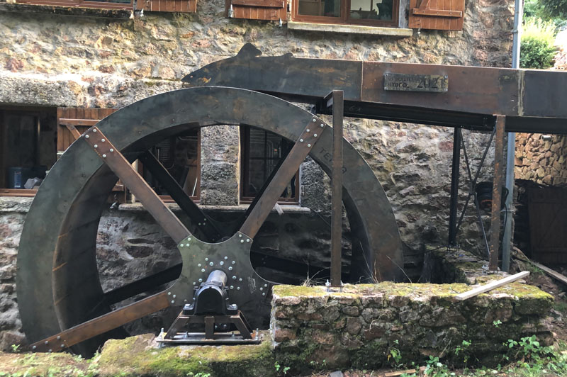
The 4.1m diameter waterwheel is positioned in an existing water supply in one of the old wheel pits of the former gunpowder works, next to The Langdale Estate’s original turbine house which generated electricity for the estate in the 19th century.
The spokes, rims and buckets were all fabricated from 3mm pre-galvanised sheet finished with polyester powder coating. These lightweight components were easily and rapidly assembled using stainless steel nuts and bolts without the need for welding or any special tools on site. Only the wheel hub required welding and this was undertaken at our factory.
Delivery to site as a flat pack kit enabled it to be installed without the need for a large crane which would have been unable to travel down the narrow road to the site. This unique feature allows our overshot wheels to be installed in remote locations where there is restricted access.
Tests undertaken with Dr Paddy Quinlan of the University of Cumbria show that high mechanical efficiencies can be achieved from our overshot wheels. A water-to-wire efficiency of 65% was expected but the tests showed it is over 75%.
The waterwheel was funded through the University of Cumbria’s Renewable Energy Test and Education Centre (RETEC) with funding from Britain’s Energy Coast in partnership with the Nuclear Decommissioning Authority.

At the water mill in Moux-en-Morvan an overshot water wheel has been placed. The generated electricity is used to drive a heat pump and supply the entire house with electricity.
The watermill has a small lake for the storage of water. This creates a reserve when more power is needed. Previously, the miller saved up water so that he had water available during working hours. This is less important for electricity production because the grid functions as a buffer. But with the storage option, the generated power can be matched to the required power. At the moment, the storage facility of the lake is not yet used, because then a regulation has to be made that operates the supply sluice depending on the required power. This is another plan for the future.
The mechanical power of the waterwheel is fed through a gearing to an induction generator. It supplies up to 5 kW of electrical power. It runs parallel to the grid. This is the simplest solution, but some provisions have been made to reduce blindness and monitor grid quality. These are both requirements of the French grid operator ENEDIS.
A monastery in Myanmar that itself generates electricity for the boarding school with 1.200 children. The installation is separate from the grid and runs in island operation. The yield was insufficient and relied heavily on a diesel generator. Gratia Hydro has given advice on how to increase the yield of hydropower and make the grid stable. This means that the polluting and expensive diesel generator only needs to serve as a backup.

The path that the water takes through a turbine and the general layout is often used for classification, like tangential-flow, radial-flow cross-flow and axial-flow. Below are the various categories of ‘water driven prime mover that can be used to convert the ‘potential energy’ in a river or stream into usable ‘mechanical’ or ‘electrical’ energy. This section continues with information on what types of turbine are suitable in various sites and applications.
Gravity devices are those where any kinetic energy present at the entry of the device is either minimal or lost in turbulence and does nor contribute measurably to the output of the device. Such devices include most waterwheel types, Archimedes screws (where the outer case rotates with the flutes); Hydrodynamic screws (as used for sewage pumping and now being used in reverse as low-head prime-movers); Norias (more commonly used for raising water) and consist of a string of buckets like an overshot waterwheel attached to form a chain, and positive displacement devices or hydraulic engines.
Impulse turbines are those where the potential energy in a ‘head of water’ is largely converted into kinetic energy at a nozzle or spout. The simplest of such devices is the Gharat or Norse Wheel (where the conversion to kinetic energy takes place in an open flume). The more conventional devices harness the potential energy in a pipeline or penstock that terminates in a nozzle. The flow path through the turbine is usually used to describe the specific device, namely, tangential-flow, radial-flow, cross-flow, axial-flow or mixed-flow. Specific turbine designers have been associated with most of these devices, though confusion can result because they often designed several different types of device (The Pelton Waterwheel Company also made cased reaction turbines, Herschel pre dates Jonval’s patent that was the precursor of the Turgo Impulse wheel, a single nozzle version developed by Gilkes. Donat Banki, a Hungarian was also making cross-flow turbines many years before Mitchell and Ossburger came on the scene.
Reaction turbines are those where the turbine runner is usually completely flooded and the transfer of energy from the water to the turbine runner is achieved by a combination of reaction and/or lift. Some designs of cross-flow turbine in common use a combination of impulse and reaction. Reaction turbines have had a more complex development, with many designers and factories adding features such as movable ‘wicket gates’ that resulted in Francis’s name becoming the tag by which this group of turbines are now known. The Kaplan turbine developed in the 1930s is a sophisticated variable geometry version of the ‘propeller turbine’ that as its name suggests is similar to a ship’s propeller in a housing. Halfway between these types is the single regulated propeller turbine, where either the runner blades or the ‘guide vanes’ (wicket gates) are adjustable.
Free-stream devices encompass large slow running wheels and turbines, some of which are being tried out for marine energy applications. Like wind turbines, the power delivered increases as a cube of the velocity, such that a doubling of the velocity gives an eight fold increase in power output. The devices themselves are very large and slow running and only have very specialised applications for extracting small amounts of power from bank-side locations on very large rivers.
High head sites with over 20 metres of fall, where the water is conveyed directly to the turbine in a pipe (penstock) or via an open canal followed by a piped section, generally use impulse turbines. The reason is that high head sites are usually subject to significant changes in water flow and reaction turbines like the Francis are not able to cope with such variations. Silt in the water can also cause a lot of damage to Francis turbines that is expensive to repair.
One of the most successful high head turbines was developed in California during the gold rush from a device referred to as a ‘hurdy gurdy’ that was basically a cartwheel with buckets around the periphery. A carpenter by the name of Lester Pelton came up with the now familiar double bucket shape and went on to found ‘The Pelton Watewheel Company’ of San Francisco. The bucket design was later improved by Doble who joined the company as an engineer in 1899. Doble’s improvement is the central cut-out in the bucket that prevents the water jet from first striking the back of the bucket and wasting energy. www.oldpelton.net. Today, similar machines are operating from over 1000 metres of fall and generating up to 100MW of power.
A simple weir is all that is required to divert the stream into the penstock (pipeline) via a de-silting chamber to remove any sand. Water storage may be included if the terrain allows and if it is advantageous to generate more power for short periods or where it is necessary to store water for generation when flows are very low. A low-pressure pipe or open canal may also be used to reduce to overall cost if it allows a short steep decent to the powerhouse using less high-pressure pipe.
Pelton turbines are efficient over a very wide range of flows but at lower heads the speed is too low for belt drives, so we reduce the pitch circle and modify the bucket shape to increase the specific speed. The jets may have plain nozzles or adjustable spear valves to adjust the water consumption to the available stream flow. It is usual with larger machines to have ‘deflectors’ that divert the water away from the runner for controlling the speed without altering the water flow. They can also be used for emergency shutdown.
Turgo Impulse turbines, the name given by Gilkes of Kendal, is a ‘jet supplied impulse turbine’ that has its origins back in the early 19c when Herschel and Jonval and latterly Gunthers of Oldham made similar turbines. The ‘Turgo’ with one or more jets is often used for lower heads where it is necessary to keep the shaft speed up for direct driving the generator. A two jet ‘Turgo’ runs at about twice the RPM of an equivalent four jet pelton, and the runner is significantly smaller but the efficiency is a little lower.
For thousands of years waterpower has been harnessed for milling and pumping water. In the Developing World many are still in daily use, but in Western Countries they have usually fallen into disrepair as a result of competition from diesel and electric power. In the U.K. there were over 70,000 working mills at the end of the 18th century and now there are a few hundred. These mills fall into a number of categories that will determine their suitability for redevelopment.
The waterwheels that were used on these sites in the U.K. are usually of the Roman or horizontal shaft type, though the vertical shaft type is much more common in Mediterranean and Asian countries. Depending on the fall of water available, the horizontal wheels are classified into ‘Overshot’, ‘Breast-shot’, ‘Back-shot’ and ‘Under-shot’. With the exception of projects to restore a mill to its original design, or where the visual appearance is important to maintain, only the overshot wheel is suitable for a new power generation projects.
Overshot waterwheels are the most fish-friendly and able to handle leaves and sticks. A similar device is the Noria or chain wheel, which has the disadvantage of potential more maintenance, but it runs faster, is more efficient and easier to install than an overshot waterwheel.
The power available is a function of the head and flow so building a large wheel will only increase the cost and reduce the shaft speed but not increase the power. Major components in the cost are the primary gearbox and the material required in the construction of the wheel itself. We are happy to build any type of waterwheel, but the cost is likely to be significantly greater than that of an equivalent turbine, when you take the gearing and installation costs into consideration. There are no short cuts with waterwheels and the engineering has to be good, on account of the high torque in the low speed drive.
Mills with ponds are seldom suitable for redevelopment for anything other than a few kilowatts because the water flow is obviously too little to sustain the mill on a continuous basis, and it is much too expensive to install a wheel or turbine that can only be operated for a few hours a day. In some cases the ponds were only used in the summer months when the water was low, but today we are looking to the higher winter flow for the bulk of the power that can be used for heating. There is always a loss of head into and out of the pond, but this may be recoverable with a turbine installation.
Mills with leats, lades or channels take their water from a water course along the side of a valley at a gradient that is usually less than one in five hundred. At a suitable point when enough fall can be achieved in one place, the mill is built. The only limitations to future development are the actual head and flow available. Since there was a mill there anyway there should be enough power for domestic purposes. Improvements to the leat and head are usually possible but are very site specific. Modern mini excavators make leat widening and maintenance much easier than when the mills were first built.
Mills on weirs or with short wide diversion channels present the most difficult challenge for the developer. The available head may only be a metre or so and the flow required to generate useful amounts of power will be several cubic metres of water per second. The undershot waterwheels that were originally used at these sites are totally redundant on account of their high cost and low efficiency. The exact layout of the site becomes increasingly important with the lower falls, because access for excavators and to install the large items of equipment is more difficult.
Open flume installations are the most usual for the very low head sites, and employ fixed geometry propeller turbines on account of their simple construction and high ‘specific speed’. The more complex variable ‘Kaplan’ type turbines are not economic for these small schemes and it is easier to achieve ‘flow control’ by installing more than one machine or by running until the water has fallen by say 100mm and then switching off automatically until it has come up again. This latter system can be used for heating
Tubular turbines of the propeller type can be used for mill sites with a higher head, typically those that originally employed ‘Overshot’ waterwheels. Many different arrangements are possible to suite existing civil works but the main compromise arises from their inflexible performance. If the mill is only extracting a small percentage of the available water from the main river, then there is no problem. If however the water flow reduces below that which is required to supply the turbine, either water storage, another smaller turbine or a change in turbine speed will be required.
Low cost open impulse turbineshave been developed by us, primarily for projects in the Developing World. Installed outside the mill house like a waterwheel, it is an economic alternative for smaller domestic sites here in the U.K. They cannot be used with a draft tube since the runner is open to the atmosphere but the installation and maintenance is much simpler. The valve control shaft is extended through the mill house wall to an operating lever on the ,inside or a simple open shoot conveys the water directly to the runner in the manner of the old ‘flutter wheels’ used in the USA in the 19c. Installation work is usually kept to a minimum and may be in an old waterwheel pit or even behind an existing wheel under the launder. A vertical shaft version like the Indian Gharat can produce considerably more power by increasing the entry area, whilst maintaining its self-cleaning characteristics.
Portable turbines are highly adaptable and be assembled on site in a few hours. Applications include ‘Rural Development’, camping and field hospitals. Typical outputs range from 200 watts to 50 kW. The inlet works are prefabricated and the pipeline is either flexible polyethylene or ‘lay-flat’ coiled pipe. The whole unit can be built into a trailer or air-portable unit for rapid deployment in the field. The buckets that are divided along their centre line by a splitter ridge, turn the jet of water that is directed at them, through 1800 so that the energy is transferred efficiently to the shaft.
Turbines that are suitable for a particular type of site and turbines that are suitable for particular type of application are referred to as ‘groups’. Hence you can have a group of ‘Hillstream’ turbines for upland sites, or a group of ‘Agricultural’ turbines for agricultural applications. The site may be defined topographically as an upland or ‘Hillstream’ site, or as a lowland or ‘Millstream’ site. Each of these groups I then divided into two sub-groups depending on the actual site layout and general features. The ‘Hillstream’ group is comprised of vertical and horizontal shaft impulse turbines that may be either direct drive, belt drive or overhung from the generator. The application for the plant may be to generate electricity, mechanically power machinery or pump water for irrigation or for a drinking water supply. The application will also have a bearing on the materials, the sophistication, the governing system and the general build.
Water wheel design has evolved over time with some water wheels oriented vertically, some horizontally and some with elaborate pulleys and gears attached, but they are all designed to do the same function and that is too, “convert the linear motion of the moving water into a rotary motion which can be used to drive any piece of machinery connected to it via a rotating shaft”.
Early Waterwheel Design were quite primitive and simple machines consisting of a vertical wooden wheel with wooden blades or buckets fixed equally around their circumference all supported on a horizontal shaft with the force of the water flowing underneath it pushing the wheel in a tangential direction against the blades.
These vertical waterwheels were vastly superior to the earlier horizontal waterwheel design by the ancient Greeks and Egyptians, because they could operate more efficiently translating the hydrokinetic energy of the moving water into mechanical power. Pulleys and gearing was then attached to the waterwheel which allowed a change in direction of a rotating shaft from horizontal to vertical in order to operate millstones, saw wood, crush ore, stamping and cutting etc.
Most Waterwheels also known as Watermills or simply Water Wheels, are vertically mounted wheels rotating about a horizontal axle, and these types of waterwheels are classified by the way in which the water is applied to the wheel, relative to the wheel’s axle. As you may expect, waterwheels are relatively large machines which rotate at low angular speeds, and have a low efficiency, due to losses by friction and the incomplete filling of the buckets, etc.
The action of the water pushing against the wheels buckets or paddles develops torque on the axle but by directing the water at these paddles and buckets from different positions on the wheel the speed of rotation and its efficiency can be improved. The two most common types of waterwheel design is the “undershot waterwheel” and the “overshot waterwheel”.
The Undershot Water Wheel Design, also known as a “stream wheel” was the most commonly used type of waterwheel designed by the ancient Greeks and Romans as it is the simplest, cheapest and easiest type of wheel to construct.
In this type of waterwheel design, the wheel is simply placed directly into a fast flowing river and supported from above. The motion of the water below creates a pushing action against the submerged paddles on the lower part of the wheel allowing it to rotate in one direction only relative to the direction of the flow of the water.
This type of waterwheel design is generally used in flat areas with no natural slope of the land or where the flow of water is sufficiently fast moving. Compared with the other waterwheel designs, this type of design is very inefficient, with as little as 20% of the waters potential energy being used to actually rotate the wheel. Also the waters energy is used only once to rotate the wheel, after which it flows away with the rest of the water.
Another disadvantage of the undershot water wheel is that it requires large quantities of water moving at speed. Therefore, undershot waterwheels are usually situated on the banks of rivers as smaller streams or brooks do not have enough potential energy in the moving water.
One way of improving the efficiency slightly of an undershot waterwheel is to divert a percentage off the water in the river along a narrow channel or duct so that 100% of the diverted water is used to rotate the wheel. In order to achieve this the undershot wheel has to be narrow and fit very accurately within the channel to prevent the water from escaping around the sides or by increasing either the number or size of the paddles.
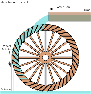
The Overshot Water Wheel Design is the most common type of waterwheel design. The overshot waterwheel is more complicated in its construction and design than the previous undershot waterwheel as it uses buckets or small compartments to both catch and hold the water.
These buckets fill with water flowing onto the wheel through a penstock design above. The gravitational weight of the water in the full buckets causes the wheel to rotate around its central axis as the empty buckets on the other side of the wheel become lighter.
This type of water wheel uses gravity to improve output as well as the water itself, thus overshot waterwheels are much more efficient than undershot designs as almost all of the water and its weight is being used to produce output power. However as before, the waters energy is used only once to rotate the wheel, after which it flows away with the rest of the water.
Overshot waterwheels are suspended above a river or stream and are generally built on the sides of hills providing a water supply from above with a low head (the vertical distance between the water at the top and the river or stream below) of between 5-to-20 metres. A small dam or weir can be constructed and used to both channel and increase the speed of the water to the top of the wheel giving it more energy but it is the volume of water rather than its speed which helps rotate the wheel.
Generally, overshot waterwheels are built as large as possible to give the greatest possible head distance for the gravitational weight of the water to rotate the wheel. However, large diameter waterwheels are more complicated and expensive to construct due to the weight of the wheel and water.
When the individual buckets are filled with water, the gravitational weight of the water causes the wheel to rotate in the direction of the flow of water. As the angle of rotation gets nearer to the bottom of the wheel, the water inside the bucket empties out into the river or stream below, but the weight of the buckets rotating behind it causes the wheel to continue with its rotational speed.
Once the bucket is empty of water it continues around the rotating wheel until it gets back up to the top again ready to be filled with more water and the cycle repeats. One of the disadvantages of an overshot waterwheel design is that the water is only used once as it flows over the wheel.
The Pitchback Water Wheel Design is a variation on the previous overshot waterwheel as it also uses the gravitational weight of the water to help rotate the wheel, but it also uses the flow of the waste water below it to give an extra push. This type of waterwheel design uses a low head infeed system which provides the water near to the top of the wheel from a pentrough above.
Unlike the overshot waterwheel which channelled the water directly over the wheel causing it to rotate in the direction of the flow of the water, the pitchback waterwheel feeds the water vertically downwards through a funnel and into the bucket below causing the wheel to rotate in the opposite direction to the flow of the water above.
Just like the previous overshot waterwheel, the gravitational weight of the water in the buckets causes the wheel to rotate but in an anti-clockwise direction. As the angle of rotation nears the bottom of the wheel, the water trapped inside the buckets empties out below. As the empty bucket is attached to the wheel, it continues rotating with the wheel as before until it gets back up to the top again ready to be filled with more water and the cycle repeats.
The difference this time is that the waste water emptied out of the rotating bucket flows away in the direction of the rotating wheel (as it has nowhere else to go), similar to the undershot waterwheel principal. Thus the main advantage of the pitchback waterwheel is that it uses the energy of the water twice, once from above and once from below to rotate the wheel around its central axis.
The result is that the efficiency of the waterwheel design is greatly increased to over 80% of the waters energy as it is driven by both the gravitaional weight of the incoming water and by the force or pressure of water directed into the buckets from above, as well as the flow of the waste water below pushing against the buckets. The disadvantage though of an pitchback waterwheel is that it needs a slightly more complex water supply arrangement directly above the wheel with chutes and pentroughs.
The Breastshot Water Wheel Design is another vertically-mounted waterwheel design where the water enters the buckets about half way up at axle height, or just above it, and then flows out at the bottom in the direction of the wheels rotation. Generally, the breastshot waterwheel is used in situations were the head of water is insufficient to power an overshot or pitchback waterwheel design from above.
The disadvantage here is that the gravitational weight of the water is only used for about one quarter of the rotation unlike previously which was for half the rotation. To overcome this low head height, the waterwheels buckets are made wider to extract the required amount of potential energy from the water.
Breastshot waterwheels use about the same gravitational weight of the water to rotate the wheel but as the head height of the water is around half that of a typical overshot waterwheel, the buckets are a lot wider than previous waterwheel designs to increase the volume of the water caught in the buckets.
The disadvantage of this type of design is an increase in the width and weight of the water being carried by each bucket. As with the pitchback design, the breastshot wheel uses the energy of the water twice as the waterwheel is designed to sit in the water allowing the waste water to help in the rotation of the wheel as it flows away down stream.
Historically water wheels have been used for milling flour, cereals and other such mechanical tasks. But water wheels can also be used for the generation of electricity, called a Hydro Power system.
By connecting an electrical generator to the waterwheels rotating shaft, either directly or indirectly using drive belts and pulleys, waterwheels can be used to generate power continuously 24 hours a day unlike solar energy. If the waterwheel is designed correctly, a small or “micro” hydroelectric system can produce enough electricity to power lighting and/or electrical appliances in an average home.
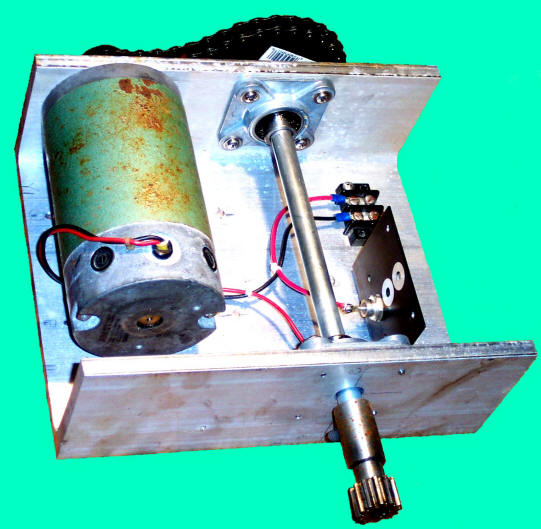
Look for Water wheel Generators designed to produce its optimum output at relatively low speeds. For small projects, a small DC motor can be used as a low-speed generator or an automotive alternator but these are designed to work at much higher speeds so some form of gearing may be required. A wind turbine generator makes an ideal waterwheel generator as it is designed for low speed, high output operation.
If there is a fairly fast flowing river or stream near to your home or garden which you can use, then a small scale hydro power system may be a better alternative to other forms of renewable energy sources such as “Wind Energy” or “Solar Energy” as it has a lot less visual impact. Also just like wind and solar energy, with a grid-connected small scale waterwheel designed generating system connected to the local utility grid, any electricity you generate but don’t use can be sold back to the electricity company.
In the next tutorial about Hydro Energy, we will look at the different types of turbines available which we could attach to our waterwheel design for hydro power generation. For more information about Waterwheel Design and how to generate your own electricity using the power of water, or obtain more hydro energy information about the various waterwheel designs available, or to explore the advantages and disadvantages of hydro energy, then Click Here to order your copy from Amazon today about the principles and construction of waterwheels which can be used for generating electricity.

Power wheels, the overshot in particular, benefits from several often overlooked design features. Operational reliability and ruggedness are very high in a practical installation, the overshot tolerates heavily silted waters, flood debris, rocks, rubbish and outright vandalism. The high rotational inertia and increased static torque create a self cleaning mechanism that breaks tangled fishing lines and carrier bags. Fish and all aquatic life are completely unaffected and water quality may be slightly improved.
The overshot and midshot wheels are very much more efficient than often stated, indeed the overshotis the most efficient energy extractor for limited applications. We make hese to any size; Our Ultra Ultra low head midshots operate in impossibly low head situations finding great favour with utilities and agencies for continuous small or transient high power demands.
We have solutions to address the specific needs applicable to domestic, water, communications and environmental management. Our special purpose team can engineer power solutions for all load demands, try our team of hardened optimists before giving up on your project ! 01525 874226

To establish if your site is suitable for generating electricity from a Poncelet Wheel you need to have flowing water and you need to know the three key components, which are WATER VELOCITY (in metres per second), AREA (in square metres) and HEAD (in metres).
The more flowing water you have, the more potential power you can generate. The Water Velocity can be estimated by recording how long (in seconds) a "floating object" (such as a ball) takes to travel over a given distance (in metres). Divide the distance by the time taken and you will have the Water Velocity (in metres per second).
.jpg)
A water wheel is a machine for converting the energy of flowing or falling water into useful forms of power, often in a watermill. A water wheel consists of a wheel (usually constructed from wood or metal), with a number of blades or buckets arranged on the outside rim forming the driving car. Water wheels were still in commercial use well into the 20th century but they are no longer in common use. Uses included milling flour in gristmills, grinding wood into pulp for papermaking, hammering wrought iron, machining, ore crushing and pounding fibre for use in the manufacture of cloth.
Some water wheels are fed by water from a mill pond, which is formed when a flowing stream is dammed. A channel for the water flowing to or from a water wheel is called a mill race. The race bringing water from the mill pond to the water wheel is a headrace; the one carrying water after it has left the wheel is commonly referred to as a tailrace.
Waterwheels were used for various purposes from agriculture to metallurgy in ancient civilizations spanning the Hellenistic Greek world, Rome, China and India. Waterwheels saw continued use in the Post-classical age, like the Middle Ages of Europe and the Islamic Golden Age, but also elsewhere. In the mid to late 18th century John Smeaton"s scientific investigation of the water wheel led to significant increases in efficiency supplying much needed power for the Industrial Revolution.turbine, developed by Benoît Fourneyron, beginning with his first model in 1827.elevations, that exceed the capability of practical-sized waterwheels.
The main difficulty of water wheels is their dependence on flowing water, which limits where they can be located. Modern hydroelectric dams can be viewed as the descendants of the water wheel, as they too take advantage of the movement of water downhill.
Overshot and backshot water wheels are typically used where the available height difference is more than a couple of meters. Breastshot wheels are more suited to large flows with a moderate head. Undershot and stream wheel use large flows at little or no head.
There is often an associated millpond, a reservoir for storing water and hence energy until it is needed. Larger heads store more gravitational potential energy for the same amount of water so the reservoirs for overshot and backshot wheels tend to be smaller than for breast shot wheels.
Overshot and pitchback water wheels are suitable where there is a small stream with a height difference of more than 2 metres (6.5 ft), often in association with a small reservoir. Breastshot and undershot wheels can be used on rivers or high volume flows with large reservoirs.
Stream wheels are cheaper and simpler to build and have less of an environmental impact, than other types of wheels. They do not constitute a major change of the river. Their disadvantages are their low efficiency, which means that they generate less power and can only be used where the flow rate is sufficient. A typical flat board undershot wheel uses about 20 percent of the energy in the flow of water striking the wheel as measured by English civil engineer John Smeaton in the 18th century.
Stream wheels mounted on floating platforms are often referred to as hip wheels and the mill as a ship mill. They were sometimes mounted immediately downstream from bridges where the flow restriction of the bridge piers increased the speed of the current.
An undershot wheel is a vertically mounted water wheel with a horizontal axle that is rotated by the water from a low weir striking the wheel in the bottom quarter. Most of the energy gain is from the movement of the water and comparatively little from the head. They are similar in operation and design to stream wheels.
The word breastshot is used in a variety of ways. Some authors restrict the term to wheels where the water enters at about the 10 o’clock position, others 9 o’clock, and others for a range of heights.
The small clearance between the wheel and the masonry requires that a breastshot wheel has a good trash rack ("screen" in British English) to prevent debris from jamming between the wheel and the apron and potentially causing serious damage.
Breastshot wheels are less efficient than overshot and backshot wheels but they can handle high flow rates and consequently high power. They are preferred for steady, high-volume flows such as are found on the Fall Line of the North American East Coast. Breastshot wheels are the most common type in the United States of America
A vertically mounted water wheel that is rotated by water entering buckets just past the top of the wheel is said to be overshot. The term is sometimes, erroneously, applied to backshot wheels, where the water goes down behind the wheel.
A typical overshot wheel has the water channeled to the wheel at the top and slightly beyond the axle. The water collects in the buckets on that side of the wheel, making it heavier than the other "empty" side. The weight turns the wheel, and the water flows out into the tail-water when the wheel rotates enough to invert the buckets. The overshot design is very efficient, it can achieve 90%,
Nearly all of the energy is gained from the weight of water lowered to the tailrace although a small contribution may be made by the kinetic energy of the water entering the wheel. They are suited to larger heads than the other type of wheel so they are ideally suited to hilly countries. However even the largest water wheel, the Laxey Wheel in the Isle of Man, only utilises a head of around 30 m (100 ft). The world"s largest head turbines, Bieudron Hydroelectric Power Station in Switzerland, utilise about 1,869 m (6,132 ft).
Overshot wheels require a large head compared to other types of wheel which usually means significant investment in constructing the headrace. Sometimes the final approach of the water to the wheel is along a flume or penstock, which can be lengthy.
A backshot wheel (also called pitchback) is a variety of overshot wheel where the water is introduced just before the summit of the wheel. In many situations, it has the advantage that the bottom of the wheel is moving in the same direction as the water in the tailrace which makes it more efficient. It also performs better than an overshot wheel in flood conditions when the water level may submerge the bottom of the wheel. It will continue to rotate until the water in the wheel pit rises quite high on the wheel. This makes the technique particularly suitable for streams that experience significant variations in flow and reduces the size, complexity, and hence cost of the tailrace.
The direction of rotation of a backshot wheel is the same as that of a breastshot wheel but in other respects, it is very similar to the overshot wheel. See below.
Some wheels are overshot at the top and backshot at the bottom thereby potentially combining the best features of both types. The photograph shows an example at Finch Foundry in Devon, UK. The head race is the overhead timber structure and a branch to the left supplies water to the wheel. The water exits from under the wheel back into the stream.
A special type of overshot/backshot wheel is the reversible water wheel. This has two sets of blades or buckets running in opposite directions so that it can turn in either direction depending on which side the water is directed. Reversible wheels were used in the mining industry in order to power various means of ore conveyance. By changing the direction of the wheel, barrels or baskets of ore could be lifted up or lowered down a shaft or inclined plane. There was usually a cable drum or a chain basket on the axle of the wheel. It is essential that the wheel have braking equipment to be able to stop the wheel (known as a braking wheel). The oldest known drawing of a reversible water wheel was by Georgius Agricola and dates to 1556.
The earliest waterwheel working like a lever was described by Zhuangzi in the late Warring States period (476-221 BC). It says that the waterwheel was invented by Zigong, a disciple of Confucius in the 5th century BC.Chinese of the Eastern Han Dynasty were using water wheels to crush grain in mills and to power the piston-bellows in forging iron ore into cast iron.
In the text known as the Xin Lun written by Huan Tan about 20 AD (during the usurpation of Wang Mang), it states that the legendary mythological king known as Fu Xi was the one responsible for the pestle and mortar, which evolved into the tilt-hammer and then trip hammer device (see trip hammer). Although the author speaks of the mythological Fu Xi, a passage of his writing gives hint that the water wheel was in widespread use by the 1st century AD in China (Wade-Giles spelling):
Fu Hsi invented the pestle and mortar, which is so useful, and later on it was cleverly improved in such a way that the whole weight of the body could be used for treading on the tilt-hammer (tui), thus increasing the efficiency ten times. Afterwards the power of animals—donkeys, mules, oxen, and horses—was applied by means of machinery, and water-power too used for pounding, so that the benefit was increased a hundredfold.
In the year 31 AD, the engineer and Prefect of Nanyang, Du Shi (d. 38), applied a complex use of the water wheel and machinery to power the bellows of the blast furnace to create cast iron. Du Shi is mentioned briefly in the Hou Han Shu) as follows (in Wade-Giles spelling):
In the seventh year of the Chien-Wu reign period (31 AD) Tu Shih was posted to be Prefect of Nanyang. He was a generous man and his policies were peaceful; he destroyed evil-doers and established the dignity (of his office). Good at planning, he loved the common people and wished to save their labor. He invented a water-power reciprocator (shui phai) for the casting of (iron) agricultural implements. Those who smelted and cast already had the push-bellows to blow up their charcoal fires, and now they were instructed to use the rushing of the water (chi shui) to operate it ... Thus the people got great benefit for little labor. They found the "water(-powered) bellows" convenient and adopted it widely.
Water wheels in China found practical uses such as this, as well as extraordinary use. The Chinese inventor Zhang Heng (78–139) was the first in history to apply motive power in rotating the astronomical instrument of an armillary sphere, by use of a water wheel.mechanical engineer Ma Jun (c. 200–265) from Cao Wei once used a water wheel to power and operate a large mechanical puppet theater for the Emperor Ming of Wei (r. 226–239).
The ancient Greeks invented the waterwheel independently and used it in nearly all of the forms and functions described above, including its application for watermilling.Hellenistic period between the 3rd and 1st century BC.
The compartmented water wheel comes in two basic forms, the wheel with compartmented body (Latin tympanum) and the wheel with compartmented rim or a rim with separate, attached containers.sakia gear.
The earliest literary reference to a water-driven, compartmented wheel appears in the technical treatise Pneumatica (chap. 61) of the Greek engineer Philo of Byzantium (ca. 280−220 BC).Parasceuastica (91.43−44), Philo advises the use of such wheels for submerging siege mines as a defensive measure against enemy sapping.dry docks in Alexandria under the reign of Ptolemy IV (221−205 BC).papyri of the 3rd to 2nd century BC mention the use of these wheels, but don"t give further details.Ancient Near East before Alexander"s conquest can be deduced from its pronounced absence from the otherwise rich oriental iconography on irrigation practices.
The earliest depiction of a compartmented wheel is from a tomb painting in Ptolemaic Egypt which dates to the 2nd century BC. It shows a pair of yoked oxen driving the wheel via a sakia gear, which is here for the first time attested, too.Museum of Alexandria, at the time the most active Greek research center, may have been involved in its invention.Alexandrian War in 48 BC tells of how Caesar"s enemies employed geared waterwheels to pour sea water from elevated places on the position of the trapped Romans.
Around 300 AD, the noria was finally introduced when the wooden compartments were replaced with inexpensive ceramic pots that were tied to the outside of an open-framed wheel.
The Romans used waterwheels extensively in mining projects, with enormous Roman-era waterwheels found in places like modern-day Spain. They were reverse overshot water-wheels designed for dewatering deep underground mines.Vitruvius, including the reverse overshot water-wheel and the Archimedean screw. Many were found during modern mining at the copper mines at Rio Tinto in Spain, one system involving 16 such wheels stacked above one another so as to lift water about 80 feet from the mine sump. Part of such a wheel was found at Dolaucothi, a Roman gold mine in south Wales in the 1930s when the mine was briefly re-opened. It was found about 160 feet below the surface, so must have been part of a similar sequence as that discovered at Rio Tinto. It has recently been carbon dated to about 90 AD, and since the wood from which it was made is much older than the deep mine, it is likely that the deep workings were in operation perhaps 30–50 years after. It is clear from these examples of drainage wheels found in sealed underground galleries in widely separated locations that building water wheels was well within their capabilities, and such verticals water wheels commonly used for industrial purposes.
Taking indirect evidence into account from the work of the Greek technician Apollonius of Perge, the British historian of technology M.J.T. Lewis dates the appearance of the vertical-axle watermill to the early 3rd century BC, and the horizontal-axle watermill to around 240 BC, with Byzantium and Alexandria as the assigned places of invention.Strabon (ca. 64 BC–AD 24) to have existed sometime before 71 BC in the palace of the Pontian king Mithradates VI Eupator, but its exact construction cannot be gleaned from the text (XII, 3, 30 C 556).
The first clear description of a geared watermill offers the late 1st century BC Roman architect Vitruvius who tells of the sakia gearing system as being applied to a watermill.
About the same time, the overshot wheel appears for the first time in a poem by Antipater of Thessalonica, which praises it as a labour-saving device (IX, 418.4–6).Lucretius (ca. 99–55 BC) who likens the rotation of the waterwheel to the motion of the stars on the firmament (V 516).central Gaul.Barbegal watermill complex a series of sixteen overshot wheels was fed by an artificial aqueduct, a proto-industrial grain factory which has been referred to as "the greatest known concentration of mechanical power in the ancient world".
In Roman North Africa, several installations from around 300 AD were found where vertical-axle waterwheels fitted with angled blades were installed at the bottom of a water-filled, circular shaft. The water from the mill-race which entered tangentially the pit created a swirling water column that made the fully submerged wheel act like true water turbines, the earliest known to date.
Apart from its use in milling and water-raising, ancient engineers applied the paddled waterwheel for automatons and in navigation. Vitruvius (X 9.5–7) describes multi-geared paddle wheels working as a ship odometer, the earliest of its kind. The first mention of paddle wheels as a means of propulsion comes from the 4th–5th century military treatise
Ancient water-wheel technology continued unabated in the early medieval period where the appearance of new documentary genres such as legal codes, monastic charters, but also hagiography was accompanied with a sharp increase in references to watermills and wheels.
The earliest excavated water wheel driven by tidal power was the Nendrum Monastery mill in Northern Ireland which has been dated to 787, although a possible earlier mill dates to 619. Tide mills became common in estuaries with a good tidal range in both Europe and America generally using undershot wheels.
Cistercian monasteries, in particular, made extensive use of water wheels to power watermills of many kinds. An early example of a very large water wheel is the still extant wheel at the early 13th century Real Monasterio de Nuestra Senora de Rueda, a Cistercian monastery in the Aragon region of Spain. Grist mills (for corn) were undoubtedly the most common, but there were also sawmills, fulling mills and mills to fulfil many other labour-intensive tasks. The water wheel remained competitive with the steam engine well into the Industrial Revolution. At around the 8th to 10th century, a number of irrigation technologies were brought into Spain and thus introduced to Europe. One of those technologies is the Noria, which is basically a wheel fitted with buckets on the peripherals for lifting water. It is similar to the undershot water wheel mentioned later in this article. It allowed peasants to power watermills more efficiently. According to Thomas Glick"s book, Irrigation and Society in Medieval Valencia, the Noria probably originated from somewhere in Persia. It has been used for centuries before the technology was brought into Spain by Arabs who had adopted it from the Romans. Thus the distribution of the Noria in the Iberian peninsula "conforms to the area of stabilized Islamic settlement".Spaniards, the technology spread to the New World in Mexico and South America following Spanish expansion
The type of water wheel selected was dependent upon the location. Generally if only small volumes of water and high waterfalls were available a millwright would choose to use an overshot wheel. The decision was influenced by the fact that the buckets could catch and use even a small volume of water.
Harnessing water-power enabled gains in agricultural productivity, food surpluses and the large scale urbanization starting in the 11th century. The usefulness of water power motivated European experiments with other power sources, such as wind and tidal mills.canals, put Europe on a hydraulically focused path, for instance water supply and irrigation technology was combined to modify supply power of the wheel.feudal state.
The water mill was used for grinding grain, producing flour for bread, malt for beer, or coarse meal for porridge.fulling mill, which was used for cloth making. The trip hammer was also used for making wrought iron and for working iron into useful shapes, an activity that was otherwise labour-intensive. The water wheel was also used in papermaking, beating material to a pulp. In the 13th century water mills used for hammering throughout Europe improved the productivity of early steel manufacturing. Along with the mastery of gunpowder, waterpower provided European countries worldwide military leadership from the 15th century.
Millwrights distinguished between the two forces, impulse and weight, at work in water wheels long before 18th-century Europe. Fitzherbert, a 16th-century agricultural writer, wrote "druieth the wheel as well as with the weight of the water as with strengthe [impulse]".Leonardo da Vinci also discussed water power, noting "the blow [of the water] is not weight, but excites a power of weight, almost equal to its own power".laws of force. Evangelista Torricelli"s work on water wheels used an analysis of Galileo"s work on falling bodies, that the velocity of a water sprouting from an orifice under its head was exactly equivalent to the velocity a drop of water acquired in falling freely from the same height.
The water wheel was a driving force behind the earliest stages of industrialization in Britain. Water-powered reciprocating devices were used in trip hammers and blast furnace bellows. Richard Arkwright"s water frame was powered by a water wheel.
The most powerful water wheel built in the United Kingdom was the 100 hp Quarry Bank Mill water wheel near Manchester. A high breastshot design, it was retired in 1904 and replaced with several turbines. It has now been restored and is a museum open to the public.
The biggest working water wheel in mainland Britain has a diameter of 15.4 m (51 ft) and was built by the De Winton company of Caernarfon. It is located within the Dinorwic workshops of the National Slate Museum in Llanberis, North Wales.
The largest working water wheel in the world is the Laxey Wheel (also known as Lady Isabella) in the village of Laxey, Isle of Man. It is 72 feet 6 inches (22.10 m) in diameter and 6 feet (1.83 m) wide and is maintained by Manx National Heritage.
During the Industrial Revolution, in the first half of the 19th century engineers started to design better wheels. In 1823 Jean-Victor Poncelet invented a very efficient undershot wheel design that could work on very low heads, which was commercialized and became popular by late 1830s. Other designs, as the Sagebien wheel, followed later. At the same time Claude Burdin was working on a radically different machine which he called turbine, and his pupil Benoît Fourneyron designed the first commercial one in the 1830s.
Development of water turbines led to decreased popularity of water wheels. The main advantage of turbines is that its ability to harness head is much greater than the diameter of the turbine, whereas a water wheel cannot effectively harness head greater than its diameter. The migration from water wheels to modern turbines took about one hundred years.
Water wheels were used to power sawmills, grist mills and for other purposes during development of the United States. The 40 feet (12 m) diameter water wheel at McCoy, Colorado, built in 1922, is a surviving one out of many which lifted water for irrigation out of the Colorado River.
Two early improvements were suspension wheels and rim gearing. Suspension wheels are constructed in the same manner as a bicycle wheel, the rim being supported under tension from the hub- this led to larger lighter wheels than the former design where the heavy spokes were under compression. Rim-gearing entailed adding a notched wheel to the rim or shroud of the wheel. A stub gear engaged the rim-gear and took the power into the mill using an independent line shaft. This removed the rotative stress from the axle which could thus be lighter, and also allowed more flexibility in the location of the power train. The shaft rotation was geared up from that of the wheel which led to less power loss. An example of this design pioneered by Thomas Hewes and refined by William Armstrong Fairburn can be seen at the 1849 restored wheel at the Portland Basin Canal Warehouse.
Australia has a relatively dry climate, nonetheless, where suitable water resources were available, water wheels were constructed in 19th-century Australia. These were used to power sawmills, flour mills, and stamper batteries used to crush gold-bearing ore. Notable examples of water wheels used in gold recovery operations were the large Garfield water wheel near Chewton—one of at least seven water wheels in the surrounding area—and the two water wheels at Adelong Falls; some remnants exist at both sites.Walhalla once had at least two water wheels, one of which was rolled to its site from Port Albert, on its rim using a novel trolley arrangement, taking nearly 90 days.water wheel at Jindabyne, constructed in 1847, was the first machine used to extract energy—for flour milling—from the Snowy River.
The early history of the watermill in India is obscure. Ancient Indian texts dating back to the 4th century BC refer to the term cakkavattaka (turning wheel), which commentaries explain as arahatta-ghati-yanta (machine with wheel-pots attached). On this basis, Joseph Needham suggested that the machine was a noria. Terry S. Reynolds, however, argues that the "term used in Indian texts is ambiguous and does not clearly indicate a water-powered device." Thorkild Schiøler argued that it is "more likely that these passages refer to some type of tread- or hand-operated water-lifting device, instead of a water-powered water-lifting wheel."
According to Greek historical tradition, India received water-mills from the Roman Empire in the early 4th century AD when a certain Metrodoros introduced "water-mills and baths, unknown among them [the Brahmans] till then".ancient India, predating, according to Pacey, its use in the later Roman Empire or China,
Around 1150, the astronomer Bhaskara Achārya observed water-raising wheels and imagined such a wheel lifting enough water to replenish the stream driving it, effectively, a perpetual motion machine.Arabic and Persian works. During medieval times, the diffusion of Indian and Persian irrigation technologies gave rise to an advanced irrigation system which bought about economic growth and also helped in the growth of material culture.
After the spread of Islam engineers of the Islamic world continued the water technologies of the ancient Near East; as evident in the excavation of a canal in the Basra region with remains of a water wheel dating from the 7th century. Hama in Syria still preserves some of its large wheels, on the river Orontes, although they are no longer in use.Murcia in Spain, La Nora, and although the original wheel has been replaced by a steel one, the Moorish system during al-Andalus is otherwise virtually unchanged. Some medieval Islamic compartmented water wheels could lift water as high as 30 metres (100 ft).Muhammad ibn Zakariya al-Razi"s Kitab al-Hawi in the 10th century described a noria in Iraq that could lift as much as 153,000 litres per hour (34,000 imp gal/h), or 2,550 litres per minute (560 imp gal/min). This is comparable to the output of modern norias in East Asia, which can lift up to 288,000 litres per hour (63,000 imp gal/h), or 4,800 litres per minute (1,100 imp gal/min).
The industrial uses of watermills in the Islamic world date back to the 7th century, while horizontal-wheeled and vertical-wheeled water mills were both in widespread use by the 9th century. A variety of industrial watermills were used in the Islamic world, including gristmills, hullers, sawmills, shipmills, stamp mills, steel mills, sugar mills, and tide mills. By the 11th century, every province throughout the Islamic world had these industrial watermills in operation, from al-Andalus and North Africa to the Middle East and Central Asia.crankshafts and water turbines, gears in watermills and water-raising machines, and dams as a source of water, used to provide additional power to watermills and water-raising machines.factory complexes built in al-Andalus between the 11th and 13th centuries.
The engineers of the Islamic world developed several solutions to achieve the maximum output from a water wheel. One solution was to mount them to piers of bridges to take advantage of the increased flow. Another solution was the shipmill, a type of water mill powered by water wheels mounted on the sides of ships moored in midstream. This technique was employed along the Tigris and Euphrates rivers in 10th-century Iraq, where large shipmills made of teak and iron could produce 10 tons of flour from corn every day for the granary in Baghdad.flywheel mechanism, which is used to smooth out the delivery of power from a driving device to a driven machine, was invented by Ibn Bassal (fl. 1038–1075) of Al-Andalus; he pioneered the use of the flywheel in the saqiya (chain pump) and noria.Al-Jazari in the 13th century and Taqi al-Din in the 16th century described many inventive water-raising machines in their technological treatises. They also employed water wheels to power a variety of devices, including various water clocks and automata.
A recent development of the breastshot wheel is a hydraulic wheel which effectively incorporates automatic regulation systems. The Aqualienne is one example. It generates between 37 kW and 200 kW of electricity from a 20 m3 (710 cu ft) waterflow with a head of 1 to 3.5 m (3 to 11 ft).
Overshot (and particularly backshot) wheels are the most efficient type; a backshot steel wheel can be more efficient (about 60%) than all but the most advanced and well-constructed turbines. In some situations an overshot wheel is preferable to a turbine.
The development of the hydraulic turbine wheels with their improved efficiency (>67%) opened up an alternative path for the installation of water wheels in existing mills, or redevelopment of abandoned mills.
The kinetic energy can be accounted for by converting it into an equivalent head, the velocity head, and adding it to the actual head. For still water the velocity head is zero, and to a good approximation it is negligible for slowly moving water, and can be ignored. The velocity in the tail race is not taken into account because for a perfect wheel the water would leave with zero energy which requires zero velocity. That is impossible, the water has to move away from the wheel, and represents an unavoidable cause of inefficiency.
The power is how fast that energy is delivered which is determined by the flow rate. It has been estimated that the ancient donkey or slave-powered quern of Rome made about one-half of a horsepower, the horizontal waterwheel creating slightly more than one-half of a horsepower, the undershot vertical waterwheel produced about three horsepower, and the medieval overshot waterwheel produced up to forty to sixty horsepower.
From the cross sectional area and the velocity. They must be measured at the same place but that can be anywhere in the head or tail races. It must have the same amount of water going through it as the wheel.
A parallel development is the hydr


 8613371530291