
overshot water wheel generator free sample

Water wheel design has evolved over time with some water wheels oriented vertically, some horizontally and some with elaborate pulleys and gears attached, but they are all designed to do the same function and that is too, “convert the linear motion of the moving water into a rotary motion which can be used to drive any piece of machinery connected to it via a rotating shaft”.
Early Waterwheel Design were quite primitive and simple machines consisting of a vertical wooden wheel with wooden blades or buckets fixed equally around their circumference all supported on a horizontal shaft with the force of the water flowing underneath it pushing the wheel in a tangential direction against the blades.
These vertical waterwheels were vastly superior to the earlier horizontal waterwheel design by the ancient Greeks and Egyptians, because they could operate more efficiently translating the hydrokinetic energy of the moving water into mechanical power. Pulleys and gearing was then attached to the waterwheel which allowed a change in direction of a rotating shaft from horizontal to vertical in order to operate millstones, saw wood, crush ore, stamping and cutting etc.
Most Waterwheels also known as Watermills or simply Water Wheels, are vertically mounted wheels rotating about a horizontal axle, and these types of waterwheels are classified by the way in which the water is applied to the wheel, relative to the wheel’s axle. As you may expect, waterwheels are relatively large machines which rotate at low angular speeds, and have a low efficiency, due to losses by friction and the incomplete filling of the buckets, etc.
The action of the water pushing against the wheels buckets or paddles develops torque on the axle but by directing the water at these paddles and buckets from different positions on the wheel the speed of rotation and its efficiency can be improved. The two most common types of waterwheel design is the “undershot waterwheel” and the “overshot waterwheel”.
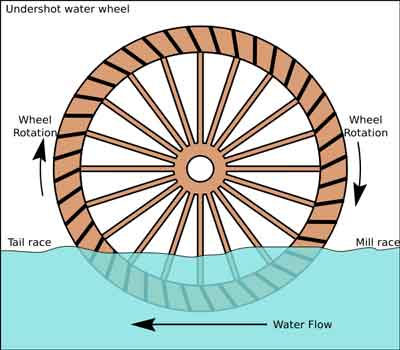
The Undershot Water Wheel Design, also known as a “stream wheel” was the most commonly used type of waterwheel designed by the ancient Greeks and Romans as it is the simplest, cheapest and easiest type of wheel to construct.
In this type of waterwheel design, the wheel is simply placed directly into a fast flowing river and supported from above. The motion of the water below creates a pushing action against the submerged paddles on the lower part of the wheel allowing it to rotate in one direction only relative to the direction of the flow of the water.
This type of waterwheel design is generally used in flat areas with no natural slope of the land or where the flow of water is sufficiently fast moving. Compared with the other waterwheel designs, this type of design is very inefficient, with as little as 20% of the waters potential energy being used to actually rotate the wheel. Also the waters energy is used only once to rotate the wheel, after which it flows away with the rest of the water.
Another disadvantage of the undershot water wheel is that it requires large quantities of water moving at speed. Therefore, undershot waterwheels are usually situated on the banks of rivers as smaller streams or brooks do not have enough potential energy in the moving water.
One way of improving the efficiency slightly of an undershot waterwheel is to divert a percentage off the water in the river along a narrow channel or duct so that 100% of the diverted water is used to rotate the wheel. In order to achieve this the undershot wheel has to be narrow and fit very accurately within the channel to prevent the water from escaping around the sides or by increasing either the number or size of the paddles.
The Overshot Water Wheel Design is the most common type of waterwheel design. The overshot waterwheel is more complicated in its construction and design than the previous undershot waterwheel as it uses buckets or small compartments to both catch and hold the water.
These buckets fill with water flowing onto the wheel through a penstock design above. The gravitational weight of the water in the full buckets causes the wheel to rotate around its central axis as the empty buckets on the other side of the wheel become lighter.
This type of water wheel uses gravity to improve output as well as the water itself, thus overshot waterwheels are much more efficient than undershot designs as almost all of the water and its weight is being used to produce output power. However as before, the waters energy is used only once to rotate the wheel, after which it flows away with the rest of the water.
Overshot waterwheels are suspended above a river or stream and are generally built on the sides of hills providing a water supply from above with a low head (the vertical distance between the water at the top and the river or stream below) of between 5-to-20 metres. A small dam or weir can be constructed and used to both channel and increase the speed of the water to the top of the wheel giving it more energy but it is the volume of water rather than its speed which helps rotate the wheel.
Generally, overshot waterwheels are built as large as possible to give the greatest possible head distance for the gravitational weight of the water to rotate the wheel. However, large diameter waterwheels are more complicated and expensive to construct due to the weight of the wheel and water.
When the individual buckets are filled with water, the gravitational weight of the water causes the wheel to rotate in the direction of the flow of water. As the angle of rotation gets nearer to the bottom of the wheel, the water inside the bucket empties out into the river or stream below, but the weight of the buckets rotating behind it causes the wheel to continue with its rotational speed.
Once the bucket is empty of water it continues around the rotating wheel until it gets back up to the top again ready to be filled with more water and the cycle repeats. One of the disadvantages of an overshot waterwheel design is that the water is only used once as it flows over the wheel.
The Pitchback Water Wheel Design is a variation on the previous overshot waterwheel as it also uses the gravitational weight of the water to help rotate the wheel, but it also uses the flow of the waste water below it to give an extra push. This type of waterwheel design uses a low head infeed system which provides the water near to the top of the wheel from a pentrough above.
Unlike the overshot waterwheel which channelled the water directly over the wheel causing it to rotate in the direction of the flow of the water, the pitchback waterwheel feeds the water vertically downwards through a funnel and into the bucket below causing the wheel to rotate in the opposite direction to the flow of the water above.
Just like the previous overshot waterwheel, the gravitational weight of the water in the buckets causes the wheel to rotate but in an anti-clockwise direction. As the angle of rotation nears the bottom of the wheel, the water trapped inside the buckets empties out below. As the empty bucket is attached to the wheel, it continues rotating with the wheel as before until it gets back up to the top again ready to be filled with more water and the cycle repeats.
The difference this time is that the waste water emptied out of the rotating bucket flows away in the direction of the rotating wheel (as it has nowhere else to go), similar to the undershot waterwheel principal. Thus the main advantage of the pitchback waterwheel is that it uses the energy of the water twice, once from above and once from below to rotate the wheel around its central axis.
The result is that the efficiency of the waterwheel design is greatly increased to over 80% of the waters energy as it is driven by both the gravitaional weight of the incoming water and by the force or pressure of water directed into the buckets from above, as well as the flow of the waste water below pushing against the buckets. The disadvantage though of an pitchback waterwheel is that it needs a slightly more complex water supply arrangement directly above the wheel with chutes and pentroughs.
The Breastshot Water Wheel Design is another vertically-mounted waterwheel design where the water enters the buckets about half way up at axle height, or just above it, and then flows out at the bottom in the direction of the wheels rotation. Generally, the breastshot waterwheel is used in situations were the head of water is insufficient to power an overshot or pitchback waterwheel design from above.
The disadvantage here is that the gravitational weight of the water is only used for about one quarter of the rotation unlike previously which was for half the rotation. To overcome this low head height, the waterwheels buckets are made wider to extract the required amount of potential energy from the water.
Breastshot waterwheels use about the same gravitational weight of the water to rotate the wheel but as the head height of the water is around half that of a typical overshot waterwheel, the buckets are a lot wider than previous waterwheel designs to increase the volume of the water caught in the buckets.
The disadvantage of this type of design is an increase in the width and weight of the water being carried by each bucket. As with the pitchback design, the breastshot wheel uses the energy of the water twice as the waterwheel is designed to sit in the water allowing the waste water to help in the rotation of the wheel as it flows away down stream.
Historically water wheels have been used for milling flour, cereals and other such mechanical tasks. But water wheels can also be used for the generation of electricity, called a Hydro Power system.
By connecting an electrical generator to the waterwheels rotating shaft, either directly or indirectly using drive belts and pulleys, waterwheels can be used to generate power continuously 24 hours a day unlike solar energy. If the waterwheel is designed correctly, a small or “micro” hydroelectric system can produce enough electricity to power lighting and/or electrical appliances in an average home.
Look for Water wheel Generators designed to produce its optimum output at relatively low speeds. For small projects, a small DC motor can be used as a low-speed generator or an automotive alternator but these are designed to work at much higher speeds so some form of gearing may be required. A wind turbine generator makes an ideal waterwheel generator as it is designed for low speed, high output operation.
If there is a fairly fast flowing river or stream near to your home or garden which you can use, then a small scale hydro power system may be a better alternative to other forms of renewable energy sources such as “Wind Energy” or “Solar Energy” as it has a lot less visual impact. Also just like wind and solar energy, with a grid-connected small scale waterwheel designed generating system connected to the local utility grid, any electricity you generate but don’t use can be sold back to the electricity company.
In the next tutorial about Hydro Energy, we will look at the different types of turbines available which we could attach to our waterwheel design for hydro power generation. For more information about Waterwheel Design and how to generate your own electricity using the power of water, or obtain more hydro energy information about the various waterwheel designs available, or to explore the advantages and disadvantages of hydro energy, then Click Here to order your copy from Amazon today about the principles and construction of waterwheels which can be used for generating electricity.

For those of you who are still awake after reading my first installment, I will now continue. This part will deal with the design factors you will need to know to build a low-head waterwheel. It’s somewhat technical, but it is essential to know if you are to build a successful no-head or low-head waterwheel.
The most important thing to determine is “head”, or how far the water falls. If you have a small dam or waterfall, the answer is the difference in height between the free water surface on the “upstream” side, and the free water surface on the “downstream” side, in inches or feet. If you have a swift moving stream, the answer is only a bit harder to figure out.
When designing an undershot wheel, you must know the “head” since the optimum diameter of the wheel is three to six times the head. Let’s say you measure your stream and get an average velocity of 10 feet-per-second. That number times itself is 100. Divided by 64.4, we get an answer of 1.55 feet. In other words, the water is moving as fast as it would if it had fallen 1.55 feet. Your wheel should then be at least 4.65 feet to 9.3 feet in diameter (E.g.: 3 x 1.55 = 4.65 or 6 x 1.55 = 9.3).
When you install the wheel, you will “submerge the blades a distance equal to the head”. Therefore, the spacing between the blades should be some convenient number times “PI” to get the working circumference. The answer will also be in feet.
In our example I have decided to work with the 9.3 foot diameter from the figurs above, so the working circumference is 24.35 feet (9.3 minus a head of 1.55 = 7.75 feet. 7.75 x PI = 24.35 feet.) The space between the blades should be less than 1.55 feet, which in our example is te head. Let’s use 1.5 feet, so the number of blades is 16.23 (24.35/1.5 = 16.23) or rounded to 16. So, we will build a wheel 9.3 feet in diameter with 16 blades.
But how fast will it turn? The most efficient energy transfer occurs when the wheel speed is between 67% and 90% of the water speed. For undershot wheels, I usually go for the lower figure to allow for slow days. Sixty seven percent of 10 feet per second is 6.7 feet per second, which is the same as 402 (6.7 x 60 =402) feet per minute. You divide this by the working circumference of 24.35 feet per revolution. This gives you an answer of 16.5 (402/24.35 = 16.5) revolutions per minute.
These calculations apply to “any” low-head waterwheel. The only thing that changes among the various designs is the speed or efficiency. If we were to make our example as a “poncelot” wheel, all the design parameters would be the same. The blades would not be straight. Instead, they would be offset from the radius of the wheel by a negative 30 degrees and the lower portion would be curved to 60 degrees of arc in a radius equal to the “head”. This change will raise efficiency to the 80+% range.
Materials should always be a good grade of steel. Asteel grade of A36 or B36 works very well. Twenty gauge or thicker is good. We always use 1/8″ at FITX Waterwheel Company, and ours have withstood direct hits by ice flows of more than a ton. If you use “corten”, a weathering steel, it will not need painting and it will acquire a reddish color that resembles wood. Staticly balance the wheel before installation.
No matter how tempting, never use wood. It rots and holds water unevenly. This unbalances the wheel and makes it unsuitable for any use except grinding grain. Be very accurate in all your measurements, especially those concerning “flow” and “head”. If they are wrong, everything is wrong.
I recommend oil-impregnated wood bearings. They can be obtained from the POBCO Bearing Company of Worcester, MA. Waterwheels turn too slowly for ball or sleeve bearings; they cannot maintain a uniform lubricant field. This tends to ruin the bearing quickly. The wood bearings have a “wick” action that maintains uniform lubricant.

To establish if your site is suitable for generating electricity from a Poncelet Wheel you need to have flowing water and you need to know the three key components, which are WATER VELOCITY (in metres per second), AREA (in square metres) and HEAD (in metres).
The more flowing water you have, the more potential power you can generate. The Water Velocity can be estimated by recording how long (in seconds) a "floating object" (such as a ball) takes to travel over a given distance (in metres). Divide the distance by the time taken and you will have the Water Velocity (in metres per second).
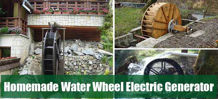
If you live by a source of running water, one option for electricity generation is a water wheel generator. I think a lot of people assume it needs to be a fairly sizeable source of running water, but if you watch the video below, you will see a water wheel generator built, running, and generating electricity from a tiny creek.
With a water wheel generator, electricity is generated when the flowing water runs through the water wheel and makes it spin. It is exactly the same principle as the old dynamo lights we used to have on bicycles, back in the day, where the electricity was generated by the revolving wheel. As I remember it used to make stopping at lights interesting, as no revolving wheel equalled zero electricity, and zero electricity equals no bike lights!
Here is a link to a tutorial on ‘Build It Solar’ which shows how to build a DIY water wheel generator from mostly recycled parts, making this an affordable DIY project if you can source the recycled parts required to build the generator. Additionally using recycled parts also allows you to source free backup, replacement part to stockpile and store in case an existing part fails. It also includes a FREE PDF with the build instructions, that you can download and print out. If you are lucky enough to have running water on your land, this would be an awesome project.
The ‘Build It Solar’ and the ‘Off-Road/Off Grid’ DIY water wheel generators are just two examples of water wheel generators. There are several different varieties of generators that utilize running water sources in different ways. Basically, the running water still turns the wheel on each model, but the wheels are positioned differently in the running water. There are ‘stream’, ‘undershot’, ‘breastshot’ and ‘backshot’ water wheels to choose from… Here is an excellent explanation of each type of water wheel, together with the pros and cons and efficiencies etc.
Here is an awesome 35 page PDF instruction manual on how to make a low-cost hydroelectric generator, in a 5-gallon bucket. I’ll be honest, it is not the simplest thing in the world to build, but if you are a competent, technically-minded DIY-er, this shouldn’t present too many difficulties.

The wheel is usually mounted inside the mill building below the working floor. A jet of water is directed on to the paddles of the water wheel, causing them to turn.
A vertically-mounted water wheel that is rotated by water striking paddles or blades at the bottom of the wheel is said to be undershot. This is generally the least efficient, oldest type of wheel.
Undershot wheels are also well suited to installation on floating platforms. The earliest were probably constructed by the Roman general Belisarius during the siege of Rome in 537.
A vertically-mounted water wheel that is rotated by falling water striking paddles, blades or buckets near the top of the wheel is said to be overshot.
In true overshot wheels the water passes over the top of the wheel, but the term is sometimes applied to backshot wheels where the water goes down behind the waterwheel.
A typical overshot wheel has the water channeled to the wheel at the top and slightly to one side in the direction of rotation. The water collects in the buckets on that side of the wheel, making it heavier than the other “empty” side. The weight turns the wheel, and the water flows out into the tail-water when the wheel rotates enough to invert the buckets.
Unlike undershot wheels, overshot wheels gain a double advantage from gravity. Not only is the force of the flowing water partially transferred to the wheel, the weight of the water descending in the wheel’s buckets also imparts additional energy.
The mechanical power derived from an overshot wheel is determined by the wheel’s physical size and the available head, so they are ideally suited to hilly or mountainous country.
Overshot wheels demand exact engineering and significant head, which usually means significant investment in constructing a dam, millpond and waterways. Sometimes the final approach of the water to the wheel is along a lengthy flume or penstock.
It combines the advantages from breastshot and overshot systems, since the full amount of the potential energy released by the falling water is harnessed as the water descends the back of the wheel.
A backshot wheel continues to function until the water in the wheel pit rises well above the height of the axle, when any other overshot wheel will be stopped or even destroyed.
A backshot wheel may also gain power from the water’s current past the bottom of the wheel, and not just the weight of the water falling in the wheel’s buckets.
A vertically-mounted water wheel design that is rotated by falling water striking buckets near the centre of the wheel’s edge, or just above it, is said to be breastshot.
The individual blades of a breastshot wheel are actually buckets, as are those of most overshot wheels, and not simple paddles like those of most undershot wheels.
Overshot and backshot wheels are the most efficient water wheel design; a backshot steel wheel can be more efficient (about 60%) than all but the most advanced and well-constructed turbines.
The development of the hydraulic water wheel design with their improved efficiency (>67%) opens up an alternative path for the installation of waterwheels in existing mills, or redevelopment of abandoned mills.

A waterwheel is a type of device that takes advantage of flowing or falling water to generate power by using a set of paddles mounted around a wheel. The falling force of the water pushes the paddles, rotating a wheel. This rotation of a wheel can be transmitted to a variety of machines through a shaft at the center of the wheel.metal with many blades or buckets along the edge of the wheel to capture the power of the moving water.
Waterwheels are usually positioned vertically over a water source. This means that the axle is positioned horizontally. This axle transfers the energy from the falling water to a drive belt or a system of gears that then operates some sort of machine. These wheels require some source of falling or flowing water, and these sources can include streams or rivers. Sometimes special ponds known as mill ponds were created by damming a flowing stream. This creates a special channel known as a
Although waterwheels are not used widely today, hydroelectric dams function on the same basic principle of using the power of flowing water to move machines known as turbines.
Overshot wheels are a type of waterwheel that can be built if there is a significant height drop in the river or body of water being used to move the wheel. Generally, these are built on the side of a hill as a drop of at least 4.5 meters.
In this type of waterwheel, the water exits the flume above the wheel itself. The water then falls down onto the blades of the waterwheel, pushing the wheel forward. The fact that water is introduced at the very top of the wheel means that the water falls the greatest distance, making the wheel highly efficient - from 80-90%.
In areas that have little to no slope, undershot waterwheels are the only type of waterwheel that will work. Since there is almost no drop in the water, these wheels are inefficient compared to other types. This is because the waterwheel relies on there being large quantities of water moving quickly to move the wheel. Because of this, the wheels tend to be built on large, strong rivers.
In this type of waterwheel, there is no flume. Instead the water rushes along the bottom of the waterwheel, spinning it backwards compared to the water flow. This spinning motion occurs because the water pushes along the blades that are in contact with the surface of the water.
Breastshot wheels are used where there is a moderate drop in the height of the water. Generally, breastshot wheels are used if there is a drop between 1.8 to 2.4 meters.iron. These wheels can be made to be very large to increase their power output.
In this type of waterwheel, water flows onto the wheel about half way up and pushes the blades of the wheel downwards as it falls. The water then continues to flow underneath the wheel, pushing it more as it flows forward.
Students learn the history of the waterwheel and common uses for water turbines today. They explore kinetic energy by creating their own experimental waterwheel from a two-liter plastic bottle. They investigate the transformations of energy involved in turning the blades of a hydro-turbine into work, and experiment with how weight affects the rotational rate of the waterwheel. Students also discuss and explore the characteristics of hydroelectric plants.
Throughout human history, waterwheels performed many types of mechanical work: saw timber, drive pumps, run farm equipment, trip hammers, grind grains into flour, make iron products and power textile mills. Today, the modern equivalents of waterwheels are the huge turbines of hydroelectric power plants, which generate electricity that we use everyday to perform all types of work: heating, cooling, refrigeration, and the powering of appliances, televisions and entertainment. Hydropower is a way to produce electricity using a renewable energy source that does not use fossil fuels, pollute or produce greenhouse gases. Yet, such big projects require engineers to consider all the implications of their impact on the surrounding environment.
Students learn how water is used to generate electricity. They investigate water"s potential-to-kinetic energy transformation in hands-on activities about falling water and waterwheels. During the activities, they take measurements, calculate averages and graph results.
Students observe a model waterwheel to investigate the transformations of energy involved in turning the blades of a hydro-turbine. They work as engineers to create model waterwheels while considering resources such as time and materials, in their designs. Students also discuss and explore the chara...
Students learn how engineers design devices that use water to generate electricity by building model water turbines and measuring the resulting current produced in a motor. Student teams work through the engineering design process to build the turbines, analyze the performance of their turbines and ...
Today we are going to talk about hydropower. Hydropower is a renewable energyresource. Hydro means water, so hydropower is something that gets power from water. Hydropower captures energyfrom the movement of water or water"s kinetic energy. Have you ever seen a waterwheel? A waterwheel is an example of how people have created a machine that uses and produces hydropower. A waterwheel is also called a turbine.
The waterwheelis one of the oldest known sources of power. A waterwheel spins as a stream of water (which is being pulled down by gravity) hits its paddles or blades. The first reference to its use is about 4000 BC. More than 2,000 years ago, farmers used waterwheels to grind wheat into flour. The gears of the wheel ground the wheat into flour. Waterwheels use the kinetic energy of moving water to perform many types of mechanical work. Waterwheels were used to power farm equipment, drive pumps, trip hammers, saw timber, grind grains into flour, forge iron, and power textile mills. Before the development of steam power during the colonial and industrial revolution eras, waterwheels were the only sources of power (besides human or animal power). Often, towns were built close to a river so waterwheels could be built nearby
Three types of waterwheels are tha horizontal waterwheel, overshot vertical waterwheel, and undershot vertical waterwheel. In the horizontal waterwheel, water flows from an aqueduct or pipe from the side of the wheel and onto the wheel. The forward motion of the water turns the wheel. In the overshot vertical waterwheel, water drops down from a water source above onto the wheel, turning it. Undershot vertical waterwheels are large vertical waterwheels placed in a stream such that the wheel is turned by the moving water.
The world"s first hydroelectric power plant began operating in 1882, on the Fox River in Appleton, WI. Hydroelectricis when water is changed into electrical energy. Hydroelectricity can be used to power lights, heaters, appliances and televisions. The plant was started by a man who was a paper manufacturer and engineer, and was inspired by Thomas Edison"s plans for an electric power plant.
Today, engineers around the world develop hydroelectric plants to meet growing energy demand. The waterwheel concept is used in dams to generate electricity. Damsare some of the largest human-made structures on Earth. In fact, the Hoover Dam on the Colorado River in Nevada is 221 meters high, 379 meters long and 14 meters wide at the top. That is pretty big! It has 17 electric generators and provides electricity for about 500,000 homes in Nevada, Arizona and California. The world"s largest hydroelectric power plant—the Itaipú Power Plant on the Paraná River in Brazil—provides energy to two countries (25% of Brazil"s electricity and 78% of Paraguay"s electricity).
The same concepts that are employed in a waterwheel are used in these gigantic hydroelectric power plants. A waterwheel is a simple turbine—a device with buckets, paddles or blades that is rotated by moving water, converting the kinetic energy of water into mechanical movement. Hydroelectric power plants use huge and more complex turbines to generate electricity.
In this activity, we are going to designa modelof an overshot vertical waterwheel. Engineers often build models or prototypesof a waterwheel or any product or large project before they build the real thing. This method of testing something on a small scale helps to prevent mistakes in making the real ones work.
With a pen or marker, draw 6 to 8 lengthwise equidistant lines along the length of the large plastic bottle. These mark the locations where index card "water catchers" will be taped.
Fold the index cards to make small boxes or envelopes ("catchers") with open sides. These will serve as waterwheel paddles (or buckets or blades) to catch the water. Exactly how the index cards are folded and attached provides an engineering design opportunity for each team.
Mark one index card with an "X" so counting the number of turns is easier. (The students will count each time the marked catcher reaches the top of the waterwheel while turning.)
Tape the index card "catchers" to the soda bottle at each line. Your waterwheel will spin in one specific direction (choose either clockwise or counterclockwise), so make sure each catcher faces the same direction to help the bottle to spin in that direction. See Figure 2.
Discuss how to measure the rate of rotation of the waterwheel (refer to the Waterwheel Worksheet). Agree on what it means for the waterwheel to slow down. Does it have to completely stop? Have the students create a procedure to count the turns of the waterwheel during a given period of time. For example, during the pouring, as the waterwheel spins, students could count the number of turns by noting how many times the marked catcher passes the top of the wheel.
(Conduct this step over a sink or outside.) Have one team member keep track of the elapsed time using the second hand on a clock or watch. As soon as the wheel is spinning, start taking the time while other team members count the number of turns the waterwheel makes. Stop counting turns and keeping track of the time when the waterwheel slows down.
Change roles and repeat until every member has counted or there is a consistent measurement for the rate at which the waterwheel spins. Record your data on the worksheet. Have students complete the front side of the worksheet.
Have teams fasten a string to the neck of their water turbines. Tie objects to the string so the spinning waterwheel pulls them up as the string rolls up around the neck of the bottle.
(Conduct this step over a sink or outside. See Figure 3.) Have one team member keep track of the elapsed time using the second hand on a clock or watch. As soon as the waterwheel (with the weight) is spinning, start taking the time while other team members count the number of turns the waterwheel makes. Stop counting turns and keeping track of the time when the waterwheel slows down. Repeat this until every member has counted or there is a consistent measurement for the rate at which the waterwheel spins. Record your data on the worksheet. Have students complete the back side of the worksheet.
potential energy: Potential energy is the energy stored by an object as a result of its position. For example, a roller coaster at the top of a hill, or water being held behind a dam.
waterwheel: A wheel that rotates by direct action of water; used to generate power or do work. The wheel often includes buckets, paddles or blades to catch the water. A simple turbine.
True or False: Hydropower dams do not interfere with natural wildlife. (Answer: False. Dams can disrupt migratory fish patterns and spawning habits, especially for species like salmon. This can have devastating effects on both the fish population and people whose livelihoods depend on these fish. Change in water levels can also fatally affect other wildlife and plants.)
Question/Answer:Ask the students how waterwheels (hydromills) and windmills are similar (Answer: Both have "vanes" and a turbine shaft, and both generate renewable energy.)
How would engineers use this understanding to design hydroelectric power plants? (Answer: Engineers would learn about the different paddle or blade designs to see how well they moved the weight. The better the blade design, the faster the waterwheel turned and moved the weight upwards. They would use this information to design a turbine that generated the most electricity from the turning wheel.)
Engineering Design Project: Divide the class into groups and inform them that they are engineering teams working for H2O Solutions, an engineering design company that specializes in waterwheels and water energy. The city has asked them to use what they have learned in this activity to design a waterwheel that is more efficient than the waterwheel they just designed during this activity. Tell the teams that they can include whatever resources (e.g., time, materials) that they want in their design. Ask them to sketch their new design. Have teams present their designs to the rest of the class.
To use the natural water flows in a river or stream for hydropower, what type of natural river conditions do engineers require? (Answer: It must be fast-moving water.)
What are some reasons why engineers construct hydroelectric power plants? (Possible answers: To produce electricity. To make use of a renewable energy source [water]. To produce electricity without polluting or producing greenhouse gases.)
Why do engineers construct dams for large hydroelectric power systems? (Answer: The dam holds a great deal of water in one place to supply the kinetic energy required to turn the turbine blades.)
How was the waterwheel you made similar to what happens in a hydroelectric power plant? (Answer: Water dropped from a container to spin the blades just like water runs from a dam to spin the blades of a turbine. The spinning waterwheel was used to do work just like the spinning blades of turbines make electricity, which we use to do work.)
Re-Design Practice:Have the students list on their worksheet any design or fabrication changes they would make to their waterwheel to make it work better.
Have students make waterwheels out of different types of materials or bottles. How does the material of the waterwheel affect the amount of work that is done? Make available bottles with different shapes and volume/capacities. Ask each team to come to the sink where the tap water is running at a constant flow rate for each. Finally, ask the students to compare their waterwheels to their peers" based on the number of turns per minute at the same flow rate of water. Ask the students why their waterwheel performs differently than the others". Which type works best? Why?
How does the size of the index card affect the efficiency of the waterwheel? Have the students measure the length and width of the index card, and find its area. After the sides of the index card have been bent to create the box-shaped "catchers," have the students calculate the volume of water that the catcher can hold. What folding method allows for the largest amount of water to be held in the catcher? Is it better to have a waterwheel catcher that can hold a lot of water or a little bit of water? Compare results as a class to find out what shapes and sizes work best!
Make some other water turbine models. See Make a Turbine Science Project at Energy Quest, at http://www.energyquest.ca.gov/projects/turbine.html and Hydro-Power Science Project at Energy Quest, at http://www.energyquest.ca.gov/projects/hydro-power.html .
Have students conduct research: How much water to do we use daily? For what purposes? Do people in other countries use as much water? What are some ways to conserve water and energy?
Have students research the history of several large dams and hydroelectric power plants, such as Aswan High Dam, Three Gorges Dam, Itaipú Dam, Guri Dam, Hoover Dam, Dalles Dam and Grand Coulee Dam. How old are they? How much electric power do they produce? How much water does each dam hold? What were the environmental concerns about building them?
For more advanced students, have them evaluate the waterwheel as an energy source. They could measure the amount of water required to turn the waterwheel a certain number of turns with a gram load. Place a large bucket under the waterwheel to capture the water. See how many turns it takes to lift an object a given distance by turning the string around the bottle of the neck. Finally, compare this idea to real energy costs. (The percent efficiency can be calculated by dividing the weight of the object by the weight of the water required to raise the object the same distance the water fell — about one foot — then multiply the result by 100.)
For more advanced students, have them explore different waterwheel variables, such as the type, shape and material of the turbine, number and position of fins on the turbine, etc.
Moving Water - Moving Blades: An Overshot Waterwheel. Hydro-Power Science Projects, Experiment with Water to Produce Energy, California Energy Commission. Accessed October 27, 2005 www.energyquest.ca.gov/projects/waterenergy.html
Water Power. Lowell National Historical Park & Tsongas Industrial History Center, National Park Service. Accessed October 27, 2005. (Good graphics of waterwheel mechanics) www.nps.gov

I’m zipping along the Massachusetts Turnpike with Julie and her friends Amaya and Natasha—the water power team. Today is our field trip—we’re driving to the town of Northfield, in western Massachusetts, to investigate the hydropower projects located there, along the Connecticut River. Julie and her team discovered Northfield while gathering information for their class project on water power. I called ahead and arranged for a tour. We’ve packed a picnic lunch, hoping to eat outside somewhere along the river.
“Oh, we each have a different part of the project,” Julie answers matter-of-factly. “We’re starting with the water cycle, ’cause that’s where water comes from in the first place. I’m doing that part, since I learned all about it last summer.”


 8613371530291