
overshot water wheel generator brands

Water wheel design has evolved over time with some water wheels oriented vertically, some horizontally and some with elaborate pulleys and gears attached, but they are all designed to do the same function and that is too, “convert the linear motion of the moving water into a rotary motion which can be used to drive any piece of machinery connected to it via a rotating shaft”.
Early Waterwheel Design were quite primitive and simple machines consisting of a vertical wooden wheel with wooden blades or buckets fixed equally around their circumference all supported on a horizontal shaft with the force of the water flowing underneath it pushing the wheel in a tangential direction against the blades.
These vertical waterwheels were vastly superior to the earlier horizontal waterwheel design by the ancient Greeks and Egyptians, because they could operate more efficiently translating the hydrokinetic energy of the moving water into mechanical power. Pulleys and gearing was then attached to the waterwheel which allowed a change in direction of a rotating shaft from horizontal to vertical in order to operate millstones, saw wood, crush ore, stamping and cutting etc.
Most Waterwheels also known as Watermills or simply Water Wheels, are vertically mounted wheels rotating about a horizontal axle, and these types of waterwheels are classified by the way in which the water is applied to the wheel, relative to the wheel’s axle. As you may expect, waterwheels are relatively large machines which rotate at low angular speeds, and have a low efficiency, due to losses by friction and the incomplete filling of the buckets, etc.
The action of the water pushing against the wheels buckets or paddles develops torque on the axle but by directing the water at these paddles and buckets from different positions on the wheel the speed of rotation and its efficiency can be improved. The two most common types of waterwheel design is the “undershot waterwheel” and the “overshot waterwheel”.
The Undershot Water Wheel Design, also known as a “stream wheel” was the most commonly used type of waterwheel designed by the ancient Greeks and Romans as it is the simplest, cheapest and easiest type of wheel to construct.
In this type of waterwheel design, the wheel is simply placed directly into a fast flowing river and supported from above. The motion of the water below creates a pushing action against the submerged paddles on the lower part of the wheel allowing it to rotate in one direction only relative to the direction of the flow of the water.
This type of waterwheel design is generally used in flat areas with no natural slope of the land or where the flow of water is sufficiently fast moving. Compared with the other waterwheel designs, this type of design is very inefficient, with as little as 20% of the waters potential energy being used to actually rotate the wheel. Also the waters energy is used only once to rotate the wheel, after which it flows away with the rest of the water.
Another disadvantage of the undershot water wheel is that it requires large quantities of water moving at speed. Therefore, undershot waterwheels are usually situated on the banks of rivers as smaller streams or brooks do not have enough potential energy in the moving water.
One way of improving the efficiency slightly of an undershot waterwheel is to divert a percentage off the water in the river along a narrow channel or duct so that 100% of the diverted water is used to rotate the wheel. In order to achieve this the undershot wheel has to be narrow and fit very accurately within the channel to prevent the water from escaping around the sides or by increasing either the number or size of the paddles.
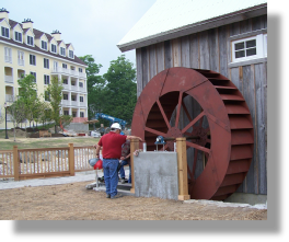
The Overshot Water Wheel Design is the most common type of waterwheel design. The overshot waterwheel is more complicated in its construction and design than the previous undershot waterwheel as it uses buckets or small compartments to both catch and hold the water.
These buckets fill with water flowing onto the wheel through a penstock design above. The gravitational weight of the water in the full buckets causes the wheel to rotate around its central axis as the empty buckets on the other side of the wheel become lighter.
This type of water wheel uses gravity to improve output as well as the water itself, thus overshot waterwheels are much more efficient than undershot designs as almost all of the water and its weight is being used to produce output power. However as before, the waters energy is used only once to rotate the wheel, after which it flows away with the rest of the water.
Overshot waterwheels are suspended above a river or stream and are generally built on the sides of hills providing a water supply from above with a low head (the vertical distance between the water at the top and the river or stream below) of between 5-to-20 metres. A small dam or weir can be constructed and used to both channel and increase the speed of the water to the top of the wheel giving it more energy but it is the volume of water rather than its speed which helps rotate the wheel.
Generally, overshot waterwheels are built as large as possible to give the greatest possible head distance for the gravitational weight of the water to rotate the wheel. However, large diameter waterwheels are more complicated and expensive to construct due to the weight of the wheel and water.
When the individual buckets are filled with water, the gravitational weight of the water causes the wheel to rotate in the direction of the flow of water. As the angle of rotation gets nearer to the bottom of the wheel, the water inside the bucket empties out into the river or stream below, but the weight of the buckets rotating behind it causes the wheel to continue with its rotational speed.
Once the bucket is empty of water it continues around the rotating wheel until it gets back up to the top again ready to be filled with more water and the cycle repeats. One of the disadvantages of an overshot waterwheel design is that the water is only used once as it flows over the wheel.
The Pitchback Water Wheel Design is a variation on the previous overshot waterwheel as it also uses the gravitational weight of the water to help rotate the wheel, but it also uses the flow of the waste water below it to give an extra push. This type of waterwheel design uses a low head infeed system which provides the water near to the top of the wheel from a pentrough above.
Unlike the overshot waterwheel which channelled the water directly over the wheel causing it to rotate in the direction of the flow of the water, the pitchback waterwheel feeds the water vertically downwards through a funnel and into the bucket below causing the wheel to rotate in the opposite direction to the flow of the water above.
Just like the previous overshot waterwheel, the gravitational weight of the water in the buckets causes the wheel to rotate but in an anti-clockwise direction. As the angle of rotation nears the bottom of the wheel, the water trapped inside the buckets empties out below. As the empty bucket is attached to the wheel, it continues rotating with the wheel as before until it gets back up to the top again ready to be filled with more water and the cycle repeats.
The difference this time is that the waste water emptied out of the rotating bucket flows away in the direction of the rotating wheel (as it has nowhere else to go), similar to the undershot waterwheel principal. Thus the main advantage of the pitchback waterwheel is that it uses the energy of the water twice, once from above and once from below to rotate the wheel around its central axis.
The result is that the efficiency of the waterwheel design is greatly increased to over 80% of the waters energy as it is driven by both the gravitaional weight of the incoming water and by the force or pressure of water directed into the buckets from above, as well as the flow of the waste water below pushing against the buckets. The disadvantage though of an pitchback waterwheel is that it needs a slightly more complex water supply arrangement directly above the wheel with chutes and pentroughs.
The Breastshot Water Wheel Design is another vertically-mounted waterwheel design where the water enters the buckets about half way up at axle height, or just above it, and then flows out at the bottom in the direction of the wheels rotation. Generally, the breastshot waterwheel is used in situations were the head of water is insufficient to power an overshot or pitchback waterwheel design from above.
The disadvantage here is that the gravitational weight of the water is only used for about one quarter of the rotation unlike previously which was for half the rotation. To overcome this low head height, the waterwheels buckets are made wider to extract the required amount of potential energy from the water.
Breastshot waterwheels use about the same gravitational weight of the water to rotate the wheel but as the head height of the water is around half that of a typical overshot waterwheel, the buckets are a lot wider than previous waterwheel designs to increase the volume of the water caught in the buckets.
The disadvantage of this type of design is an increase in the width and weight of the water being carried by each bucket. As with the pitchback design, the breastshot wheel uses the energy of the water twice as the waterwheel is designed to sit in the water allowing the waste water to help in the rotation of the wheel as it flows away down stream.
Historically water wheels have been used for milling flour, cereals and other such mechanical tasks. But water wheels can also be used for the generation of electricity, called a Hydro Power system.
By connecting an electrical generator to the waterwheels rotating shaft, either directly or indirectly using drive belts and pulleys, waterwheels can be used to generate power continuously 24 hours a day unlike solar energy. If the waterwheel is designed correctly, a small or “micro” hydroelectric system can produce enough electricity to power lighting and/or electrical appliances in an average home.
Look for Water wheel Generators designed to produce its optimum output at relatively low speeds. For small projects, a small DC motor can be used as a low-speed generator or an automotive alternator but these are designed to work at much higher speeds so some form of gearing may be required. A wind turbine generator makes an ideal waterwheel generator as it is designed for low speed, high output operation.
If there is a fairly fast flowing river or stream near to your home or garden which you can use, then a small scale hydro power system may be a better alternative to other forms of renewable energy sources such as “Wind Energy” or “Solar Energy” as it has a lot less visual impact. Also just like wind and solar energy, with a grid-connected small scale waterwheel designed generating system connected to the local utility grid, any electricity you generate but don’t use can be sold back to the electricity company.
In the next tutorial about Hydro Energy, we will look at the different types of turbines available which we could attach to our waterwheel design for hydro power generation. For more information about Waterwheel Design and how to generate your own electricity using the power of water, or obtain more hydro energy information about the various waterwheel designs available, or to explore the advantages and disadvantages of hydro energy, then Click Here to order your copy from Amazon today about the principles and construction of waterwheels which can be used for generating electricity.

The overshot wheel is the most common wheel seen in North America. It is a gravity wheel. This means that it harnesses the force of gravity acting vertically on the water as it travels from the top to the bottom of the wheel. Properly designed for a particular site, and correctly timed, an overshot The overshot wheel is most effective when it turns as slowly as possible and can still handle the total flow of water available to it. The optimal rim speed should be only about 3 feet per second. The larger the wheel the slower it will need to turn. The incoming water must be traveling about three times the rim speed of the wheel so that it can fill the buckets effectively. This requires a foot or more of head above the wheel, usually controlled by a gate.
When the head, or fall of water was not sufficient for a large diameter overshot wheel, the breast wheel often is used. This is halfway between the overshot and undershot wheels. Water strikes the buckets of the breast wheel about midway between top and bottom, using the weight of the water for a 90 degree segment of arc. Their efficiency is far less than the overshot, which uses the weight of the water for a full 180 degrees.
This type of waterwheel relies on the flow of water, coming along the base flowing at a good rate of speed to push or thrust the waterwheel. This type of waterwheel is used on mills built on rivers or streams that do not have any height or (head). Undershot wheels are normally narrow and have to have the channel walls very close to the sides of the wheel to maximize the flow of water to pass through the wheels to generate power. This type of wheel is generally the least efficient type of wheel - usually in the 30-50% range. The exception to this is the Poncelet wheel that can get up to 80% efficiency if the channel is properly constructed and the buckets are designed right.
This type of waterwheel relies on the flow of water, generally in an open stream. This type of wheel is generally the least efficient type of wheel - usually in the 30-40% range. The exception to this is the Poncelet wheel that can get up to 80% efficiency if the channel is properly constructed and the buckets are designed right.
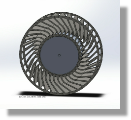
Many micro hydro electric generation strategies have evolved in recent years. Helical Ribbons, Under Water Blade Turbines, Tide and Wave action mechanical generators. Our approach is to simplify sustainable micro hydroelectric water wheel construction and improve the efficiency of energy generation. Our recent association with Ticho Industries in Italy has produced a new form of micro hydro waterwheels with a high efficiency electric generator mounted safely on the axle completely within the water wheel structure. This design simplifies micro hydro water wheel design for optimal water flow location mounting, system longevity, ease of maintenance and simplified electro mechanical connection. Our new design was created for city and rural stream based flows - including the outflows from major hydro electric dams, major navigation and irrigation dams, manufacturing and water treatment facilities.
The path that the water takes through a turbine and the general layout is often used for classification, like tangential-flow, radial-flow cross-flow and axial-flow. Below are the various categories of ‘water driven prime mover that can be used to convert the ‘potential energy’ in a river or stream into usable ‘mechanical’ or ‘electrical’ energy. This section continues with information on what types of turbine are suitable in various sites and applications.
Gravity devices are those where any kinetic energy present at the entry of the device is either minimal or lost in turbulence and does nor contribute measurably to the output of the device. Such devices include most waterwheel types, Archimedes screws (where the outer case rotates with the flutes); Hydrodynamic screws (as used for sewage pumping and now being used in reverse as low-head prime-movers); Norias (more commonly used for raising water) and consist of a string of buckets like an overshot waterwheel attached to form a chain, and positive displacement devices or hydraulic engines.
Impulse turbines are those where the potential energy in a ‘head of water’ is largely converted into kinetic energy at a nozzle or spout. The simplest of such devices is the Gharat or Norse Wheel (where the conversion to kinetic energy takes place in an open flume). The more conventional devices harness the potential energy in a pipeline or penstock that terminates in a nozzle. The flow path through the turbine is usually used to describe the specific device, namely, tangential-flow, radial-flow, cross-flow, axial-flow or mixed-flow. Specific turbine designers have been associated with most of these devices, though confusion can result because they often designed several different types of device (The Pelton Waterwheel Company also made cased reaction turbines, Herschel pre dates Jonval’s patent that was the precursor of the Turgo Impulse wheel, a single nozzle version developed by Gilkes. Donat Banki, a Hungarian was also making cross-flow turbines many years before Mitchell and Ossburger came on the scene.
Reaction turbines are those where the turbine runner is usually completely flooded and the transfer of energy from the water to the turbine runner is achieved by a combination of reaction and/or lift. Some designs of cross-flow turbine in common use a combination of impulse and reaction. Reaction turbines have had a more complex development, with many designers and factories adding features such as movable ‘wicket gates’ that resulted in Francis’s name becoming the tag by which this group of turbines are now known. The Kaplan turbine developed in the 1930s is a sophisticated variable geometry version of the ‘propeller turbine’ that as its name suggests is similar to a ship’s propeller in a housing. Halfway between these types is the single regulated propeller turbine, where either the runner blades or the ‘guide vanes’ (wicket gates) are adjustable.
Free-stream devices encompass large slow running wheels and turbines, some of which are being tried out for marine energy applications. Like wind turbines, the power delivered increases as a cube of the velocity, such that a doubling of the velocity gives an eight fold increase in power output. The devices themselves are very large and slow running and only have very specialised applications for extracting small amounts of power from bank-side locations on very large rivers.
High head sites with over 20 metres of fall, where the water is conveyed directly to the turbine in a pipe (penstock) or via an open canal followed by a piped section, generally use impulse turbines. The reason is that high head sites are usually subject to significant changes in water flow and reaction turbines like the Francis are not able to cope with such variations. Silt in the water can also cause a lot of damage to Francis turbines that is expensive to repair.
One of the most successful high head turbines was developed in California during the gold rush from a device referred to as a ‘hurdy gurdy’ that was basically a cartwheel with buckets around the periphery. A carpenter by the name of Lester Pelton came up with the now familiar double bucket shape and went on to found ‘The Pelton Watewheel Company’ of San Francisco. The bucket design was later improved by Doble who joined the company as an engineer in 1899. Doble’s improvement is the central cut-out in the bucket that prevents the water jet from first striking the back of the bucket and wasting energy. www.oldpelton.net. Today, similar machines are operating from over 1000 metres of fall and generating up to 100MW of power.
A simple weir is all that is required to divert the stream into the penstock (pipeline) via a de-silting chamber to remove any sand. Water storage may be included if the terrain allows and if it is advantageous to generate more power for short periods or where it is necessary to store water for generation when flows are very low. A low-pressure pipe or open canal may also be used to reduce to overall cost if it allows a short steep decent to the powerhouse using less high-pressure pipe.
Pelton turbines are efficient over a very wide range of flows but at lower heads the speed is too low for belt drives, so we reduce the pitch circle and modify the bucket shape to increase the specific speed. The jets may have plain nozzles or adjustable spear valves to adjust the water consumption to the available stream flow. It is usual with larger machines to have ‘deflectors’ that divert the water away from the runner for controlling the speed without altering the water flow. They can also be used for emergency shutdown.
Turgo Impulse turbines, the name given by Gilkes of Kendal, is a ‘jet supplied impulse turbine’ that has its origins back in the early 19c when Herschel and Jonval and latterly Gunthers of Oldham made similar turbines. The ‘Turgo’ with one or more jets is often used for lower heads where it is necessary to keep the shaft speed up for direct driving the generator. A two jet ‘Turgo’ runs at about twice the RPM of an equivalent four jet pelton, and the runner is significantly smaller but the efficiency is a little lower.
For thousands of years waterpower has been harnessed for milling and pumping water. In the Developing World many are still in daily use, but in Western Countries they have usually fallen into disrepair as a result of competition from diesel and electric power. In the U.K. there were over 70,000 working mills at the end of the 18th century and now there are a few hundred. These mills fall into a number of categories that will determine their suitability for redevelopment.
The waterwheels that were used on these sites in the U.K. are usually of the Roman or horizontal shaft type, though the vertical shaft type is much more common in Mediterranean and Asian countries. Depending on the fall of water available, the horizontal wheels are classified into ‘Overshot’, ‘Breast-shot’, ‘Back-shot’ and ‘Under-shot’. With the exception of projects to restore a mill to its original design, or where the visual appearance is important to maintain, only the overshot wheel is suitable for a new power generation projects.
Overshot waterwheels are the most fish-friendly and able to handle leaves and sticks. A similar device is the Noria or chain wheel, which has the disadvantage of potential more maintenance, but it runs faster, is more efficient and easier to install than an overshot waterwheel.
The power available is a function of the head and flow so building a large wheel will only increase the cost and reduce the shaft speed but not increase the power. Major components in the cost are the primary gearbox and the material required in the construction of the wheel itself. We are happy to build any type of waterwheel, but the cost is likely to be significantly greater than that of an equivalent turbine, when you take the gearing and installation costs into consideration. There are no short cuts with waterwheels and the engineering has to be good, on account of the high torque in the low speed drive.
Mills with ponds are seldom suitable for redevelopment for anything other than a few kilowatts because the water flow is obviously too little to sustain the mill on a continuous basis, and it is much too expensive to install a wheel or turbine that can only be operated for a few hours a day. In some cases the ponds were only used in the summer months when the water was low, but today we are looking to the higher winter flow for the bulk of the power that can be used for heating. There is always a loss of head into and out of the pond, but this may be recoverable with a turbine installation.
Mills with leats, lades or channels take their water from a water course along the side of a valley at a gradient that is usually less than one in five hundred. At a suitable point when enough fall can be achieved in one place, the mill is built. The only limitations to future development are the actual head and flow available. Since there was a mill there anyway there should be enough power for domestic purposes. Improvements to the leat and head are usually possible but are very site specific. Modern mini excavators make leat widening and maintenance much easier than when the mills were first built.
Mills on weirs or with short wide diversion channels present the most difficult challenge for the developer. The available head may only be a metre or so and the flow required to generate useful amounts of power will be several cubic metres of water per second. The undershot waterwheels that were originally used at these sites are totally redundant on account of their high cost and low efficiency. The exact layout of the site becomes increasingly important with the lower falls, because access for excavators and to install the large items of equipment is more difficult.
Open flume installations are the most usual for the very low head sites, and employ fixed geometry propeller turbines on account of their simple construction and high ‘specific speed’. The more complex variable ‘Kaplan’ type turbines are not economic for these small schemes and it is easier to achieve ‘flow control’ by installing more than one machine or by running until the water has fallen by say 100mm and then switching off automatically until it has come up again. This latter system can be used for heating
Tubular turbines of the propeller type can be used for mill sites with a higher head, typically those that originally employed ‘Overshot’ waterwheels. Many different arrangements are possible to suite existing civil works but the main compromise arises from their inflexible performance. If the mill is only extracting a small percentage of the available water from the main river, then there is no problem. If however the water flow reduces below that which is required to supply the turbine, either water storage, another smaller turbine or a change in turbine speed will be required.
Low cost open impulse turbineshave been developed by us, primarily for projects in the Developing World. Installed outside the mill house like a waterwheel, it is an economic alternative for smaller domestic sites here in the U.K. They cannot be used with a draft tube since the runner is open to the atmosphere but the installation and maintenance is much simpler. The valve control shaft is extended through the mill house wall to an operating lever on the ,inside or a simple open shoot conveys the water directly to the runner in the manner of the old ‘flutter wheels’ used in the USA in the 19c. Installation work is usually kept to a minimum and may be in an old waterwheel pit or even behind an existing wheel under the launder. A vertical shaft version like the Indian Gharat can produce considerably more power by increasing the entry area, whilst maintaining its self-cleaning characteristics.
Portable turbines are highly adaptable and be assembled on site in a few hours. Applications include ‘Rural Development’, camping and field hospitals. Typical outputs range from 200 watts to 50 kW. The inlet works are prefabricated and the pipeline is either flexible polyethylene or ‘lay-flat’ coiled pipe. The whole unit can be built into a trailer or air-portable unit for rapid deployment in the field. The buckets that are divided along their centre line by a splitter ridge, turn the jet of water that is directed at them, through 1800 so that the energy is transferred efficiently to the shaft.
Turbines that are suitable for a particular type of site and turbines that are suitable for particular type of application are referred to as ‘groups’. Hence you can have a group of ‘Hillstream’ turbines for upland sites, or a group of ‘Agricultural’ turbines for agricultural applications. The site may be defined topographically as an upland or ‘Hillstream’ site, or as a lowland or ‘Millstream’ site. Each of these groups I then divided into two sub-groups depending on the actual site layout and general features. The ‘Hillstream’ group is comprised of vertical and horizontal shaft impulse turbines that may be either direct drive, belt drive or overhung from the generator. The application for the plant may be to generate electricity, mechanically power machinery or pump water for irrigation or for a drinking water supply. The application will also have a bearing on the materials, the sophistication, the governing system and the general build.
Water wheels have been used for thousands of years to pump water, forge iron, grind grain, saw wood and many other applications. The most ancient water wheels exploited the kinetic energy of flowing water and were called stream water wheels. Water wheels that used the potential energy of water were introduced later and were called gravity water wheels (the water exerts a pressure on the blades due to its weight). Water wheels were in widespread use until the end of 19th century, when large hydropower plants replaced them.
Nowadays, water wheels are being recognized once again as a promising technology, especially in the micro hydropower field for electricity generation (installed power typically lower than 100 KW). Water wheels work well with very low heads and flow rates, for example in irrigation and mill canals, where conventional turbines (such as Kaplanturbines) are economically not viable. Water wheels are eco-friendly machines because fish can pass through them unharmed. Furthermore, their payback periods are shorter (7-12 years) concerning Kaplan installations. The European Small Hydropower Association estimates that in Europe about 350,000 sites suitable for similar micro hydropower plants exist.
Water wheels can be considered as old machines, with low efficiency and simple design. Therefore, with the aim of both filling the gap of engineering information on water wheels and shedding more light on their hydraulic behavior and efficiency, we have built up an experimental channel to test them (Politecnico di Torino, Turin, Italy).
We firstly investigated a breastshot water wheel, installing in the laboratory a 1:2 scale model of an existing one as seen in image accompanying this article. In breastshot wheels, water enters into the buckets from the upstream side of the wheel, near or under the rotation axle. We found a maximum hydraulic efficiency of 75% constant over a wide range of flow rates; the efficiency can improve up to 80% using an inflow weir instead of a sluice gate at the inlet. Theoretical and dimensionless models to predict the power losses and the power output were also elaborated as engineering tools, and Computational Fluid Dynamic (CFD) simulations were performed to investigate the effect of the blade number and shape on the performance. These results have shown that the filling process of the buckets is the most important process to optimize in the engineering design.
We then investigated the efficiency of overshot water wheels. In this kind of water wheel, the water enters into the buckets from the top, exerting the pressure which drives the wheel on the blades along the downstream side of the wheel. We again found that the maximum efficiency was constant over a wide range of flow rates and rotational speeds, with a maximum of 85%. We also developed a theoretical model to estimate the power losses and the efficiency, with significant similarities between the conceptual and experimental results. The experimental results have shown that at flow rates higher than the maximum optimal one, a big amount of flow rate is not exploited by the wheel, generating a decrease in efficiency. Therefore, we are currently performing CFD simulations to investigate a new design to improve the efficiency in these conditions.
To conclude, we can say that water wheels are competitive and efficient hydropower converters in low head applications. The vast diffusion of suitable sites and their low cost make them very attractive and promising. The design of a water wheel is not banal: an optimal one is what distinguishes a good water wheel plant from an ancient one.
Emanuele Quaranta is project officer (scientific research) at the Joint Research Center of the European Commission (Water Directorate), while previously was post Ph.D. researcher at Politecnico di Torino (Turin, Italy) in hydraulic engineering, hydropower (expert in water wheels), eco-hydraulics (focus on fish passages) and fluid mechanics (CFD simulations). Emanuele was hydropower expert for European Commission in 2017.

Water wheels are generally perceived as being inefficient energy converters which belong to the past, with no role for the future. But as Gerald Müller, Klemens Kauppert and Rüdiger Mach explain, they can actually be efficient and cost-effective in low head micro hydro applications
IN EUROPE, a large number of low head micro hydro power sites (head = <5m, power = <100kW) exist. Water power was a prime power source during the industrial revolution and thousands of water mills were built at low head sites. Today however, the large majority of such hydro power sources is not exploited due to the lack of a cost-effective hydraulic power converter. Recently, a number of developments appear to have opened up the possibility to generate electricity economically at low head sites. These developments include the two oldest hydraulic machines, namely water wheels and the Archimedian screw - the latter working in reverse as a power source rather than as a pump.
Water wheels are today often considered to be relics from the beginning of the industrial revolution; romantic but inefficient hydraulic machines made of wood and belonging to the past. It is generally believed that turbines are much more efficient than water wheels and subsequently took over their role as hydraulic power converters. The statistics however show a different picture. In Bavaria - a German province with an area of 70,500km2 - there were 7554 operational water wheels counted as late as 1927, with power outputs ranging from 0.75 to 75kW. In the middle of the 19th century, a high stage of development was reached when Zuppinger designed the most modern and efficient water wheel. Engineers, manufacturers and mill owners must have regarded water wheels as commercially interesting power sources. During the 1940s however, virtually all water wheels seem to have disappeared.
Today, some companies in Germany (Bega, Hydrowatt) and the US (Water Wheel Factory) are again manufacturing water wheels for electricity generation. The performance characteristics of such wheels still appear to be largely unknown. Assessment of the available power potential, comparisons with other turbine types such as the Kaplan or the Ossberger (crossflow) turbine, and even the determination of optimum operating conditions for water wheels, relies on estimates.
"Modern" water wheels, ie water wheels built using scientific principles, are made of steel and employ only the potential energy of the water since in low head flows the potential energy exceeds the kinetic energy of the flow by far. These water wheels can be divided into three fundamental types:
Water wheels were, in the large majority of cases, used to drive machinery and reached efficiencies of 75-89%. This development seems to have subsequently been forgotten.
In Karlsruhe, Germany, a small non-profit research company (IFMW - Institut für Forschung und Medien im Wasserbau) has been set up which specialises in hydraulic engineering research, and in particular in the development and promotion of low head hydro power. Within the company, a very detailed literature and market review on water wheels was conducted in order to assess the suitability of water wheels for electric power production. Since only over and undershot wheels are currently built, the discussion will be limited to those two types.
The overshot wheel receives its feeding water at the top of the wheel, catches the water in buckets or "cells" and releases the water at the lowermost possible elevation. In order to make maximum use of the energy contained in the water, the cells are shaped so as to receive the water at its natural angle of fall and then to retain it as long as possible.
Some measurements of the performance characteristics of overshot wheels were conducted in 1928, as shown in the figure below. It was found that the efficiency of a water wheel reaches 85%.
The undershot wheel was developed for the utilisation of very low heads from 0.5-2m. Whereas in ancient times the kinetic energy of the flow was utilised with a paddle-type wheel, "modern" undershot wheels built after Zuppinger"s design employ the potential energy only. The figure below shows a Zuppinger wheel with the typical "backwards" inclined curved blades.
Wheel diameters range from 4-7m, with head differences from 0.5 to 1.5m. The blades are arranged in a way so as to avoid losses at the water entry, then gradually reduce the head of water in each cell and finally to discharge the water, again with a minimum of losses. The wheel blades are curved to allow for a gentle decrease of the water level from upstream to downstream, and to minimise losses at the downstream end. In an engineering textbook from 1939 it was stated that efficiencies of 76% can be guaranteed for properly designed undershot wheels.
Recently, the undershot wheel has also experienced a small renaissance. Hydrowatt has built and installed 15 Zuppinger wheels over the last nine years, with diameters ranging from 4-7.5m, and widths of 0.5-3m. Hydraulic heads utilised ranged from 1-2.2m, with typical flow rates of 1.5-3.1 m3/sec, giving power outputs from 4-45kW of electrical power. The overall efficiency (from hydraulic power available to electric power out) was estimated as ranging from 60 to 65%.
In the UK, many smaller streams were made navigable by building weirs, many of which still exist. Generally, the head differences were in the range between 1.2-1.8m. The undershot wheel may offer a possibility to produce electric power from such weir sites. The picture below shows a typical weir situation (Eel weir on the Lagan river in Northern Ireland) with a virtual water wheel inserted. The water wheel actually fits into a "natural" environment very well, indicating that a modern machine can become a visually attractive feature too.
The Archimedian screw has been known since antiquity as a simple machine for the lifting of water. Today, Archimedian screws are still in widespread use as pumps for sewage, grain and so on. It has the advantage of being a very simple machine, with only one moving part and two bearings. It was however only recently noticed that the screw could also - in its reverse role - be employed as energy converter, termed hydraulic screw. Large scale experiments with a hydraulic screw of 8.6m length and 2.35m drop were conducted at Prague Technical University in the Czech Republic in order to assess the performance of the hydraulic screw in its power generation mode.
The screw shown in the picture above was designed for a maximum flow rate of Qmax = 0.35 m3/sec. In experiments, it reached an efficiency of 70% for Q/Qmax = 0.4, and 80% for 0.6 < Q/Qmax < 1.0. The screw rotates at 53rpm, so that fewer gear ratios than for a comparable water wheel are required to achieve the speed necessary for electricity generation. To the author"s knowledge, six hydraulic screws have been installed already. Some design guidance for hydraulic screws, based on the design experience with screw pumps and generator experiments, is also available.
The economics of micro hydro converters are a function of variable boundary conditions such as electricity prices and so on. In Germany, overshot water wheels are currently built (including installation and grid connection) for 4360-4850 US$/kW. Undershot wheels cost 7760-9700 US$/kW, Archimedian screws approximately 8250-8730 US$/kW installed capacity. For comparison, low head Kaplan turbines cost 14500-15500 US$/kW. Although water wheels and the Archimedian screw have significant cost advantages over turbines, micro hydro installations are economical only if the owner uses the generated electricity at least partially, such as for a small business. Assuming 50% of self use, 6000 hours of operation per year at nominal capacity, a small business electricity price of 11 c/kWh and a price of 7.3 c/kWh for electricity fed into the grid, the following pay back periods apply:
The general perception amongst the public as well as many engineers is that water wheels are inefficient energy converters and belong to the past. Water wheels, and in particular the overshot variety, are however very efficient and cost-effective energy converters for low head micro hydro power applications. Today, the wider application of water wheels seems to suffer from a lack of information on water wheels, the lack of any design guidance and - possibly the most important aspect - the lack of actual data about the performance of such wheels.
Apparently, no performance data at all exists for undershot wheels, whereas some information is available on overshot wheels in old reports. IFMW Karlsruhe is currently conducting a detailed review and analysis of the experimental data available on overshot wheels with a view to application of such wheels for electricity generation.
The determination of performance characteristics for overshot wheels, and the publication of such data, will be the next task of the company, followed by a detailed evaluation of undershot wheels.
The use of the Archimedian screw for power generation is a recent idea. A lot of data and design expertise does however exist from the application of the Archimedian screw as a pump, and large scale experiments in the generator role were conducted so that the design methodology of Archimedian screws is quite developed.
Ecological aspects are today a major issue in the design of hydro power installations. Both the water wheel and the Archimedian screw are considered to be very fish friendly because of the large compartments for the water and the slow speed, even for long fish like eel, thus giving them a considerable advantage over the fast rotating Kaplan turbines.

To establish if your site is suitable for generating electricity from a Poncelet Wheel you need to have flowing water and you need to know the three key components, which are WATER VELOCITY (in metres per second), AREA (in square metres) and HEAD (in metres).
The more flowing water you have, the more potential power you can generate. The Water Velocity can be estimated by recording how long (in seconds) a "floating object" (such as a ball) takes to travel over a given distance (in metres). Divide the distance by the time taken and you will have the Water Velocity (in metres per second).


 8613371530291