
overshot wheel manufacturer

The overshot wheel is the most common wheel seen in North America. It is a gravity wheel. This means that it harnesses the force of gravity acting vertically on the water as it travels from the top to the bottom of the wheel. Properly designed for a particular site, and correctly timed, an overshot The overshot wheel is most effective when it turns as slowly as possible and can still handle the total flow of water available to it. The optimal rim speed should be only about 3 feet per second. The larger the wheel the slower it will need to turn. The incoming water must be traveling about three times the rim speed of the wheel so that it can fill the buckets effectively. This requires a foot or more of head above the wheel, usually controlled by a gate.
When the head, or fall of water was not sufficient for a large diameter overshot wheel, the breast wheel often is used. This is halfway between the overshot and undershot wheels. Water strikes the buckets of the breast wheel about midway between top and bottom, using the weight of the water for a 90 degree segment of arc. Their efficiency is far less than the overshot, which uses the weight of the water for a full 180 degrees.
This type of waterwheel relies on the flow of water, coming along the base flowing at a good rate of speed to push or thrust the waterwheel. This type of waterwheel is used on mills built on rivers or streams that do not have any height or (head). Undershot wheels are normally narrow and have to have the channel walls very close to the sides of the wheel to maximize the flow of water to pass through the wheels to generate power. This type of wheel is generally the least efficient type of wheel - usually in the 30-50% range. The exception to this is the Poncelet wheel that can get up to 80% efficiency if the channel is properly constructed and the buckets are designed right.
This type of waterwheel relies on the flow of water, generally in an open stream. This type of wheel is generally the least efficient type of wheel - usually in the 30-40% range. The exception to this is the Poncelet wheel that can get up to 80% efficiency if the channel is properly constructed and the buckets are designed right.
Many micro hydro electric generation strategies have evolved in recent years. Helical Ribbons, Under Water Blade Turbines, Tide and Wave action mechanical generators. Our approach is to simplify sustainable micro hydroelectric water wheel construction and improve the efficiency of energy generation. Our recent association with Ticho Industries in Italy has produced a new form of micro hydro waterwheels with a high efficiency electric generator mounted safely on the axle completely within the water wheel structure. This design simplifies micro hydro water wheel design for optimal water flow location mounting, system longevity, ease of maintenance and simplified electro mechanical connection. Our new design was created for city and rural stream based flows - including the outflows from major hydro electric dams, major navigation and irrigation dams, manufacturing and water treatment facilities.
Waterwheel Factory shares it"s knowledge about waterwheels and displays the inherent beauty of a moving waterwheel. Explore; water wheels in history; waterwheel calculations; waterwheels for energy, and gristmill restorations. Explore the many ways you can enjoy having your own waterwheel for landscape decoration or any project you may have in mind.Sit back, relax, and enjoy the many exciting photo’s and options we offer.
To establish if your site is suitable for generating electricity from a Poncelet Wheel you need to have flowing water and you need to know the three key components, which are WATER VELOCITY (in metres per second), AREA (in square metres) and HEAD (in metres).

Please Note: I have not reproduced all of the photos mentionedon the pages in these sections. I have repoduced some photos in the "images"section, and some in section called "Water Wheel Albums," seeFitz Water Wheel pages. For a complete text and all the photos, please ordera reprint copy from the Mill Bookstore of the
The Fitz I-X-L Steel Overshoot Water Wheel is the product of three generationsof unbroken experience in the design and manufacture of water wheels. Ithigh efficiency is due to its correct mechanical principles and to its carefuldesign and construction.
The manufacture of Overshoot Water Wheels was begun by Samuel Fitz, in Hanover,Pennsylvania., U. S. A., in the year 1840. The industry has been carriedon continuously since that time on the same site under the management ofthe son and grandson of the original founder.
The earlier Fitz Wheels were, of course built of wood. A number of ordersare still being received for iron parts for wooden water wheels, as describedlater in this booklet, but by far the greater part of the business donetoday is the manufacture of the all-steel Overshoot Water Wheels, in whichthe company specializes.
The real credit for the invention of the modern Steel Overshoot Water Wheeland for its development into its present highly efficient form must be givento the late John Fitz. [John Fitz, Inventor and Manufacturer. Born April15, 1847 - Died, April 12, 1914. "He originated the modern Steel OvershootWater Wheel, and rescued from oblivion one of the most useful principlesof Hydraulics."] Very early in his business career he realized thegreat possibilities of this type of water wheel and he devoted the greaterpart of his life to the study of its principles and the improvement of itsefficiency. How well he succeeded is shown by the high regard in which theSteel Overshoot is held today. In spite of this, we have not relaxed outefforts for further improvements, but are constantly striving for stillbetter results in every detail of construction.
The knowledge and experience accumulated by out organization during itslong career in the water wheel business forms an ever greater asset thanout well equipped modern factory. Most of out employees have grown up withus, and our millwrights and mechanics have been trained in this line fromearly youth. In reckoning with your water power problems, therefore, wehave a vast fund of practical experience to draw from and we are glad toplace this freely at the service of out customers.
The Overshoot Water Wheel derives its power directly from the force ofgravity. The illustration shows the principle upon which it works. The weightof the water which is admitted to the buckets, loads one side of the wheel,causing it to revolve.
The water should be applied to the top of the wheel at a point about teninches back of the vertical center line, so that the buckets will fill upjust as they pass over the topmost point of the wheel.
The diameter of an overshoot wheel should be from 2 1/2 to 3 feet less thanthe total fall available. By total fall, we mean the vertical distance fromthe surface of the water in the fore bay or "tank" above the topof the wheel, down to the surface of the water in the tail race or dischargecanal, below the bottom of the water wheel.
Wheels of all types were formerly built of wood. Many picturesque examplesof this method of construction are still to be found in rural districts.The overshoot wheel possessed so many advantages that it soon displacedthe other early types of water wheels. Even with all its crude design andill-suited material, the wood overshoot still persists as a strong competitorof the modern small turbine.
The field of the Overshoot Wheel lies in the development of small powers.It is not suitable for use in very large developments on account of theincrease in size and weight of the wheel as the head and discharge are increasedbeyond certain limits. It can be built in any diameter needed up to 60 feetand in any width desired up to a capacity of 3,000 cubic feet per minutein single units.
The power of an overshoot wheel depends upon both the diameter of the wheeland the width of the wheel. The larger the diameter of an overshoot wheel,the more power it will develop with the same amount of water. The widerthe wheel is made, the more water it will accommodate. The relative powerof two wheels of the same diameter is of course in direct proportion tothe amount of water each wheel is capable of using, if other conditionsare equal. The question of determining the proper size wheel to use forany particular location is one which should usually be left to the judgmentof the builder of the wheel. We do not publish any list of sizes of wheelsin this booklet for the reason that we prefer to have our customer giveus the data, so that we, ourselves, can select the size of wheel he oughtto have.
For any location within the range of its capacity, the overshoot type ofwheel possesses certain decided advantages, over all other types of waterwheels, viz.:
The extent to which any overshoot wheel makes use of these advantages dependslargely upon design of the wheel, its accuracy of construction and the materialof which it is made. The Fitz Steel Overshoot Water Wheel makes use of thesame basic principles as the old wood overshoot, but its superior designenables the Fitz Wheel to develop more than 90% efficiency as compared withthe 60% to 70% efficiency of the wood wheel. The reasons for this are setforth in detail later on in this booklet under the heading "Comparisonwith wood wheels." The efficiency of the Fitz Wheel is not a matterof opinion or guess work. Our wheels are rated according to the resultsshown by rigid test on Hydraulic Testing Flumes.
Developing an efficiency of 90% or more, the Fitz Steel Overshoot is vastlymore efficient than any other type of water wheel known. In the smallerinstallations especially, where the overshoot most frequently competes witha turbine, it is doubtful whether the turbines ever operates with an efficiencyhigher than 70%. It is true that many turbine builders claim high efficienciesfor their wheels, but every experienced turbine user has good reason toknow how far the turbines themselves fall short of their makers" claimswhen confronted with actual running conditions. In every case, where theamount of fall and quantity of flow is suitable for our type of wheel, aFitz Overshoot will develop at least one-third more power than any turbineworking under similar conditions, or 25% more than the best new wood wheelthat can be built.
The above statements are made without prejudice to the turbine type of waterwheel, for we build a turbine wheel ourselves that ranks fully equal tothe best on the market. We are just as glad to sell a turbine wheel as weare to sell an overshoot where the conditions are suitable for a wheel ofthat type, but we will not furnish either kind for a location where we knowthat out customers" interests require the other.
The development of the overshoot water wheel into its present state ofunrivalled efficiency has been the results of many years of thought andeffort. Founded in its present location nearly ninety years ago, this firmhas been building water wheels continuously during all that time, but ithas never ceased to improve and modernize its product.
Up until the advent of the modern Fitz Steel Overshoot Water Wheel an efficiencyof 60% to 70% was considered remarkably good for small water power plant.Today, practically every recent text-book on hydraulics concedes an efficiencyof 90% or more to the "modern steel overshoot water wheel when properlyconstructed." Proper construction means "Fitz Construction,"for no other make of water wheel has approached this high efficiency. FitzWater Wheels form part of the equipment of some of the greatest engineeringcolleges and universities of the world. They have been adopted by many railroadsand by many of the leading engineering firms in this country for use whereverhigh efficiency and perfect reliability are the essential requirements ina small water power development.
A range of four hundred per cent in variation of the amount of water suppliedto this water wheel showed a difference of only 5% in the efficiency ofthe wheel. We quote as follows from an article in the "EngineeringNews" of January 2, 1913, by Prof. Carl R. Weidner, Instructor in HydraulicEngineering at the university of Wisconsin:
"To engineers familiar with the variation in efficiency of the turbineat part gate, a glance at the curves obtained from the Wisconsin experimentswill be convincing as to the superiority of the overshoot wheel in respectto its adaptability to varying discharge."
"The result of the experiments show high efficiencies under a widerange of operating conditions. Reliable test of turbines have been reportedyielding as high as 89% efficiency but it is rarely that this figure isobtained in an actual installation. In the smaller plants, especially, wherean overshoot wheel would be capable of competing with a turbine, it is doubtfulwhether the turbines operate with an average efficiency higher than 70%."
"Laboratory test of a machine, when properly interpreted, undoubtedlyhave great value, but it must be borne in mind, that any test so made representsresults under the exact conditions of the test. The conditions under whichthe Wisconsin experiments were performed approached practical conditionsvery closely. The wheel tested was of a standard pattern taken from thestock of the manufacturers. The structure features are simple, and noneof these features, of the wheel itself, were changed during the tests. Theresults should, therefore, be readily duplicated in actual service, if thewheel is set properly."
The published test reports of the university of Wisconsin show the ten footdiameter Fitz Wheel above illustrated, mounted on out bronze lined bearings,yielded an efficiency of 89%, on the water wheel shaft.
Later tests of this same wheel, made under the same supervision but withthe mounting changed to our self-aligning ball bearings, showed an efficiencyof 92%. [Note this was the only water wheel efficiency testing done andreport published in this century]
The power developed at any water power installation depends on three factors,viz.: The volume of water in the stream, the amount of fall and the kindof water wheel used. The first two factors are usually determined by thenatural conditions and are nearly always developed to the greatest practicableextent. They fix the potential or theoretical power. The water wheel isthe medium by which the potential or possible power is converted into actualprofit-earning power.
There is a great difference in water wheels. Failure to realize this facthas caused many water power projects to result in disappointment. Afterspending perhaps, thousands of dollars on the dam, race-way, flume, excavating,etc., to develop a power, it is a very poor policy to sacrifice a largepart of the returns by putting in a wasteful, inefficient water wheel. Awater wheel of low efficiency may only develop half, or less than half,the possible power of the location. That means a sacrifice of one-half theearnings capacity of the plant. And that is just what nineteenths of theturbines and wood wheels in existence are doing for their owners. The remainingtenth are doing better than this but not one of them is giving anythinglike the actual power it should give.
A man with a valuable water power cannot afford to take an inefficient wheelas a gift. His water power is valuable just in proportion to its earningcapacity, and its earning capacity is regulated by the amount of power developed.A wasteful water wheel cuts down the value of the whole plant in proportionto the amount.
A water power plant usually represents not only the investment of a considerablesum of money in the dam, race-way, flume, tail race, etc., but also in thevalue of the factory which it operates, since that can earn but little withoutthe power. The cost of the best water wheel on earth is but a fraction ofthe value of the entire plant which depends on it. Too much care cannotbe used in the selection of a water wheel. Only the best and most efficienton the market should be considered. That is the only wise and economicalpolicy.
By repeated tests the Fitz Overshoot Water Wheel has shown that it willdevelop at least 33 1/3 more power than the best turbine made using thesame amount of water. We are well aware that some turbine builders claimfrom 80% to 85% efficiency for their wheels and pretend that this is provenby their records in the testing flume. Such claims are absurd. It is truethat a few turbines have given a little over 80% efficiency in the laboratorywhen tested at full gate, but it must be remembered that these were largewheels built regardless of expense and working under the most favorableconditions known. Even in the case of the large turbines, the practicalvalue of these tests may be seen from the fact that no two wheels of thesame size and same make would give the same efficiency, and often the samewheel, when tested at different times, would vary considerably. Small turbines,such as out wheel competes with, have never shown good results even in laboratorytest.
It is well known that conditions are much less favorable to turbines inactual use that to those in the testing flume, and that when you buy a turbinefrom any builder you don"t get near as good a wheel as the one he buildsespecially to be tested. We know it to be a fact that there is no turbinebuilt today that will develop over 65% to 70% efficiency in actual use,and the great majority fall much below this. See the extracts on the followingpages from some leading reference works in regard to this.
But it is not enough to merely consider the efficiency of a wheel with afull head of water. It is just as important to know how a wheel will actwith a diminished head or scanty supply of water. No stream of water isof the same size at all seasons and a wheel that is not adaptable to varyingconditions is useless a large part of the year. This is the point whereall turbines, despite the claims of their makers, fail absolutely, for unlessthey are run a full gate, or nearly so, they will do very little work. Thesteel overshoot is a model wheel in this regard, as in every other respect,for it will run just as economical at one-fourth gate as at full gate, whilewhen water is plentiful, it can be crowded far beyond its normal capacity.
The Fitz Wheel depends only to a small extent upon pressure for its power.It can adapt itself to a wide range of heads. This feature is especiallyvaluable where water is scarce and a large pond is used to store the waterover night. Every one knows how unsatisfactory it is to use a turbine whereyou have to run by heads. Since the turbine depends upon the pressure ofthe water, when the head diminishes naturally the speed diminishes and alsothe power. With the Fitz the head can be drawn down almost to the bottomof the race without affecting either the power or the speed.
Besides these most important consideration of high efficiency and adaptabilityto varying conditions, there are five other points that an ideal wheel shouldpossess, viz.:
These points are only to be found in the Fitz Steel Overshoot Water Wheel.The large buckets cannot possibly become clogged with leaves, sticks, oranything else, like turbine buckets, for whatever goes through the gatewill pass over the wheel freely. Ice, which causes so much trouble withwood wheels and turbines, has but little effect upon the steel overshoot.It cannot form on the wheel as long as it is in motion, for the thin steelreadily acquires the temperature of the water passing over it and remainsabove the freezing point. Even should any ice form on the wheel while standing,a few strokes with a hammer will cause the wheel to ring like a bell andwill shiver the ice all off, for there is nothing for it to cling to.
The gate of our wheel is simplicity itself. It is tight beyond comparisonwith turbine gates. The balance of the wheel is very accurate. The wheelcan be easily turned by one hand no mater how large it is. As for durability,it leaves nothing to be desired. The first wheels we ever built are stillrunning and are in first-class condition right now.
Back water, which will soon stop a wood overshoot, has very much less effecton the Fitz wheel. We usually calculate out wheels to accommodate from one-fourthto one-half more water than the normal volume of the streams which drivethem. Consequently at flood periods more water can be used on the wheel,thus overcoming the loss of head in back-water.
A careful consideration of the above facts must lead the conclusion thatthe Fitz Steel Overshot is not only the best water wheel on the market butalso the cheapest, for it gives much the best value for the money expended.This wheel utilizes every bit of water to its fullest possible extent. Thevalue of the increased power alone, that it yields, may be worth more everyyear than the whole cost of the water wheel, to say nothing of its greaterdurability and more satisfactory service.
The Fitz Steel Overshoot Water Wheel is built entirely of iron and steel.Its high efficiency is due to its correct principles of design and to thehigh class workmanship and material used in its construction.
The word "Overshoot" is simply our arbitrary spelling which weadopted some time ago to distinguish our wheel from the ordinary "overshot"water wheel. For the sake of brevity our wheel is sometimes referred toby its old name, "The I-X-L," or often as "The Fitz Wheel."
We do not wish to convey the impression that the Fitz Overshoot is the bestwheel for all locations or for all conditions. Our field is in the developmentand improvement of small water powers. By small water powers we mean thosehaving falls of less than sixty feet and volumes of water smaller than 3,000cubic feet per minute for single units of wheels. Even within those limits,there are certain conditions to be met with occasionally which call forother types of water wheels. Within its own field, however, there is noother type of water wheel in the world that can compete with the Fitz Wheel.Put your conditions up to our engineers and let us tell you what we cando for you. We will guarantee in every case to greatly improve your poweror to let it alone.
The site of an overshoot wheel depends largely upon the situation, but weusually make the diameter about 2 1/2 feet less than the amount of the actualworking head.
The force of the water above our wheel is not lost but acts by its impulseupon the wheel just as it act on a turbine or impulse wheel. In other typesof overshoot wheels this force is almost entirely wasted but the shape ofour buckets and our method of applying the water to the wheel enable usto utilize this impulse. As will be seen from the cut on page eighteen,the water spurts across our smooth steel chute at a tangent to the crownof the wheel. It enters the buckets a little back of the vertical centerline of the wheel and glides along the curved part of the bucket, strikingthe heel of the bucket at right angles to the radius of the wheel drawnto that point. Thus its power is communicated to the wheel in the directionbest adapted to produce the greatest effect.
The curve of the bucket is not the same in all sizes of wheels. It is variedto suit the particular requirements. Proper allowance is made in all casesto permit the exit of air from the bucket when water is entering. The shapeof the bucket is such as to retain the water until all possible power istaken from it. The water is actual retained in the buckets almost to thelevel of the surface of the tail race.
The housing if the steel overshoot, instead of coming flush with the bucketsas in a wood wheel, are extended so as to prevent any water splashing overthe sides. Thus not a drop of water is wasted and the water is dischargedin the tail race with all its power extract. Compare the calm stream flowingfrom the overshoot wheel with the rushing torrent discharged by the turbineand you will see one of our strongest points. Mighty few small turbinesget more than 60% or 65% of the energy out of the water that they use, andthe momentum of the tail race represents a considerable part of the remaining35% or 40%.
Practically no power is wasted by friction in the bearing of our wheels.Fitz Wheels are so perfectly balanced and run with so little friction thata little child can turn the largest wheel we ever built, with one hand.Thus we are able to transmit undiminished to the jack shaft, nearly allof the energy we have extracted from the water.
With each wheel we usually furnish our "water-tight" iron gateand steel "chute." Our iron gate is a very valuable feature. Onsmall streams in very dry weather, it is essential to save all the waterpossible. A wood wheel or a turbine will often allow enough water to leakaway at night through its defective gates, to run a Fitz Overshoot for severalhours a day. The Fitz gate consists of two parts, a smoothly planed ironframe, and a movable slab which is both planed and scraped to insure a veryaccurate fit. It is tight and at the same time it is almost perfectly trouble-proof.The chute is the steel trough which carries the water from the gate to thebuckets of the wheel. This piece is necessary in every case, in order toapply the water to the wheel at the proper tangent.
The object of all wheels is to utilize the weight of falling water and todevelop power thereby. The Fitz Wheel does this in the most direct mannerand therefore with the least loss. Turbines and other wheels, aim to developtheir power in an indirect manner by reaction or impulse caused by pressure.To give even moderately good results they must be geared to run at certainspeed, under a certain pressure and using a certain amount of water. Sincethe overshoot depends mainly on the positive weight of the water and onlyin a small degree on impulse, it can run fast or slow, with high head orlow head, at full gate or fractional gate with equally high efficiency,and developing power in exact proportion to the amount of water used.
The motion of the Fitz Overshoot is slow. In order to drive fast runningmachinery the wheel should be equipped with suitable gearing. Later on inthis booklet, the reader will find a number of plans showing approved methodsof connecting up various kinds of machinery to our wheels.
Fitz (I-X-L) Steel Overshoot Water Wheels are shipped "knocked down"in sections easy to handle. The rim or "buckets" comes in fromeight to twenty sections, according to the diameter of the wheel. Everypiece is carefully marked or numbered and we furnish full printed instructionsfor assembling with each wheel, as well as a blue-print drawing showingthe setting. The arms are numbered to suit the pockets of the flanges towhich they belong. The sections of the rim and the segments of the gearare likewise numbered to correspond with their respective positions.
We can furnish a skilled mechanic from our factory to install our wheelswhen wanted, but our careful method of marking an the perfect "fit"of each piece makes it very easy for the purchaser to install the work himself.
The bolts and rivets used in our wheels are selected with great care. Theyare absolutely the best that can be bought. For specially heavy servicewe make our bolts out of nickel-chrome-vanadium steel. Patented Nut Locksare used wherever necessary. Our gears are cast from semi-steel in our ownfoundry and are much stronger and tougher that cast gearing.
With a large stream of clear water which never varies in volume, andwith a good fall, a well made turbine will work very satisfactorily. Itis true that the efficiency of small turbine water wheels is always overrated,very few of them in practical use giving over 60% of the power they shoulddevelop, but of course where there is an abundance of water it is not necessaryto be economical. But on a light stream, or wherever it is desirable toget the full power from the water, they are failures. The capacity of aturbine is unhangable. If you have more water than you need, it is wasted.If less, it will hardly turn the wheel. The reverse is true of the Fitz,as its adaptability to varying conditions is one of its strongest points.When water is scarce it will develop the full percentage of power, whilewith an abundance of water the wheel can be crowded far beyond its normalcapacity.
A turbine depends for its power upon the reaction or impulse of the waterdischarged under pressure of the working head. The pressure is due to theweight of the water and is proportional to the working head of water overthe wheel. The higher the head the greater the pressure, and hence the velocityof the water discharged. The wheel must run at a certain proportionate velocity,the buckets must be curved at a certain angle, and the water must be dischargedin a certain volume in order to do good work. All these points must be rightin order to obtain even 60% to 70% efficiency. they are fixed by the volumeof the stream to be used and the amount of water secured. Most streams areconstantly varying in volume and it is impossible to supply the wheel withthe same amount of water or to keep up the same head, so the conditionsare seldom favorable for a turbine to reach its maximum efficiency. It cannotadapt itself to the changed conditions of diminished supply or lowered head.Consequently in dry weather, when economy of water is most necessary, theturbine is most wasteful, and will do practically no work at all.
Of course we are aware that all turbine manufacturers table their wheelsat 80% efficiency, or higher, and that nearly every one claims that he alonehas solved the impossible problem of making a turbine to work equally wellat partial gate as at full gate. These foolish claims are a result of conditionsestablished many years ago. Since it is the universal custom, the turbineman who did not make such claims could get no hearing for his wheel. Thecustomer has usually no means of testing his wheel and does not realizethe outrageous discrepancy between the power promised by the turbine men,and the results actually attained.
An interesting side light on some of the losses which make impossible thehigh efficiency of any turbine wheel is shown by the following extract froma book entitled "Turbine Water Wheel Tests," written by RobertE. Horton, and published (1906) by the United States Geological Survey,("Water Supply and Irrigation Paper No. 180") page 22:
Remember that these losses occur in every turbine. Some of them are quiteimportant. Take for instance the one item of leakage through only one ofthe clearance spaces. Even a perfectly new turbine wheel has some clearancebetween the runner and the case. Water escaping through this opening undervery heavy pressure and carrying sand and grit, soon enlarges this clearanceuntil it is 1/4" wide or more. Take a 20" turbine inch 24 foothead. That means a stream of water 3.4" thick by 63" (the circumferenceof the wheel) under a pressure of 24 feet escaping all the time withoutever going through the buckets at all. The gate leakage is also a heavyitem of loss.
The Fitz Steel Overshoot Water Wheel will deliver at least a third morepower than the best turbine using the same amount of water, because it developsits power by utilizing the weight of the water in the simplest and mostdirect manner possible, instead of indirectly through impulse or reaction,as in the turbine. The water is received from the fore bay in such a manneras to utilize as much as possible of the impulse due to the head in thefore bay, and is retained by the correctly curved water tight buckets untilit reaches the center again at the bottom, where it is discharged in a calmstream with all the energy extracted. There is no occasion for loss of powerin this process; no splashing, no leaking or spilling too soon.
If half the normal quantity of water is used on a Fitz Overshoot wheel itwill develop half the power, or one fourth the power with one fourth thewater, thus showing that its efficiency is unimpaired by the changed conditions.No power is lost by friction, for a child can turn our largest wheel withone hand.
A great deal of trouble is experienced by turbine users in hilly or sandylocalities where the frequent floods and freshets wash down great quantitiesof sand and grit, which are very hard on their wheels. The leaves, sticksand other trash which get into the buckets and choke up the narrow ventsare also a constant annoyance and frequently stop the wheels. The turbineflume, if built of wood, requires constant attention and repairs. The gatesare invariably leaky after a few months" use and waste a great deal of water.The complicated construction of some turbines make them particularly aptto get out of order, but they all give more or less annoyance in this regard.
None of these troubles have any effect whatever upon the Fitz Steel Overshoot.There is nothing about it to break or get out of order. Every part is exposedto view and easily accessible, but the only attention required is to oilthe bearing occasionally. The gate is as near perfection as possible foranything which has to work in water, and owing to its simple constructionwill remain for years just as tight as the day it was put in. The largebuckets cannot possibly choke up no matter how dirty the stream is, foranything that will pass through the gate will pass over the wheel withoutthe slightest injury.
The condensed experience of thousands of water power owners shows that ifyou have more water at all seasons of the year than you can use, so thateconomy of water is no object to you, then you can use a turbine satisfactorily,provided you are not greatly troubled with sand or trash in your stream.But if you want to get all out of your water power that there is in it;to develop the highest efficiency at all times, no matter how low the wateris; if you want durability and freedom from repairs; economy and satisfactoryresults, then the Fitz Steel Overshoot Water Wheel is the only wheel onthe market worthy of your consideration.
The wood overshoot still survives as an active competitor of the smallturbine in some parts of the country. On a light stream, as well made woodwheel will often give better results than a turbine, but it always fallsfar short of getting the full possible power from the water.
Wood is not a fit material to use in building a water wheel. A high efficiencywheel must be made of metal. Wood overshoots have been built for centuries,but up until the advent of the Fitz, an efficiency of 75% was consideredthe limit for an overshoot wheel of any kind. Mighty few wood wheels everapproach that efficiency today.
The buckets of a wood wheel cannot be shaped to a suitable curve to receiveand discharge the water properly. A wood wheel is invariably out of balanceand its jerky motion is destructive to good results from the machinery itoperated. The constant swelling and drying of the wood soon causes all partsto get loose; the buckets leak; and a considerable proportion of the energyis wasted.
In a steel wheel, the buckets can be shaped to suit the design required.The Fitz steel bucket is shaped so as to receive the water at the crownof the wheel with the least possible shock. It retains the water to a pointjust a little above the level of the tail race. In other words, the watergets to work on a Fitz wheel at least three buckets earlier than it doeson other wheels, and it stays on the wheel from three to ten buckets longer,depending upon the diameter of the wheel.
A wood wheel gets no benefit from the head of water over the top of thewheel. In order to put the water into the thick straight, wood buckets,the chute is generally slanted a good deal and the water is allowed to "drop"on to the wheel in the manner illustrated on page 31. The water consequentlystrikes the wheel at an ineffective angle and its energy is dissipated inshock, instead of being communicated to the wheel.
This loss is more serious than the casual observer would suppose. In thecase of a 14 foot diameter water wheel, for instance, the total head isusually at least 16 or 16 1/2 feet. Two feet of that total head are in thedepth of the water in the fore bay over the top of the wheel. If the waterwheel does not utilize that 2 feet of head (and a wood wheel never can),then it is wasting 12 or 12 1.2% of the power at this point alone.
The illustration of the steel wheel on this page, or better yet, the largercut on page 18 will show clearly how the water is applied to a Fitz Wheel.Our steel chute is set nearly level. The water guides over the smooth steelwith very little loss of friction, and shoots into the steel buckets ina direction just tangent to the crown of the wheel. Its energy is thus appliedto the wheel at the most effective angle. The buckets are given just theright curve to enable them to receive the water with the least possiblewaste of power by "shock." Study the photos on pages 17, 31, and36 showing Fitz Wheels, photographed while running, and compare these wheelswith the splashing, sloppy, leaky wood wheels to be found everywhere.
In cold weather, ice gathers on the arms and shaft of a wood wheel, puttingit to a terrible strain and often causing it to stop running. Every onewho has attempted to cut ice from a wood wheel knows what a difficult anddangerous job it is and how frequently it must be done on a severe winter.Wood is a non-conductor of heat and altho the water which is running overthe wheel is usually warmer than the freezing point, the wood wheel willgather ice rapidly along its housings and arms. The water splashing overthe sides of the wheel freezes on the shaft and walls. The ice freezes rightinto pores of the water soaked wood, and is very difficult to dislodge.
Ice does not affect the steel wheel, because steel is a good conductor ofheat. The steel buckets readily assume the same temperature to the housingsand soling, so that no ice will gather on the wheel while running. Evenif, thru a leaky fore bay, some ice is allowed to form on the wheel standingidle at night, that ice will wash off the wheel when the water is turnedon in the morning. Ice cannot get into the pores of the steel, and hencehas no opportunity to cling to it like it does to wood.
In very cold countries, we house the wheel in, so as to protect it fromthe cold winds. The friction of the running water;liberates a certain amountof heat in the wheel room and prevents any trouble from anchor ice. Thefreedom of the Fitz Wheel from ice of all kinds is one of its strongestpoints. Neither the turbine nor the impulse wheel can compare with it, inits immunity from trouble with slush ice or frazil ice. Our wheels are inmost successful use all along our extreme northern border and in many provincesof Canada, in situations where a wood wheel would be impossible, and whereturbines have proven very troublesome on account of ice.
About six inches of the fall is usually wasted in the slant of a wood chuteand the clearance between the floor of the chute and the inside of the buckets.This space is all saved in a steel wheel. Several inches can be frequentlygained at the bottom of the wheel for the reason that the steel bucketsrequire less clearance from the tail race. We build all our wheels to suitthe locations where they are to go and are glad to advise out customersas to the proper size to fill their individual requirements.
A wood wheel is completely paralyzed by a little back water. Our smoothsteel buckets create much less friction than wood buckets when wading inback water. They are ventilated so as to avoid creating a vacuum when dischargingthe water, and consequently do not suck up water as a wood wheel does. Werate our wheels at the power they develop with buckets filled only 3/4 full.When it is necessary for them to run in back water, the buckets can be filledup full. One of our 17 foot diameter wheels driving the pumping plant ofthe Hanover & McSherrystown Water Co., near our town, frequently wadesin back water to depth of six feet without affecting its work. Water isplentiful at such times and more can be used on the wheel to overcome theloss of head.
A water soaked wood wheel weights three times as much as a steel wheel andthe friction of the bearing is many times greater. Standing idle for oneday, the wood wheel absorbs water on one side and is then out of balance.Its jerky motion wastes both water and power. No machinery requiring a smooth,even speed can be driven successfully with it. It is impossible for a FitzWheel to get out of balance. It runs so smoothly that its speed can readilybe controlled by the Fitz Automatic Water Wheel Governor.
The life of a wood wheel is short, not much over ten years as a rule. Theold time wood wheels lasted longer, but the old time material is no longeravailable, and the old time millwright is fast disappearing. A FItz Wheelwill out last a number of wood wheels. The metal wheels built in 1852, atour shops at Martinsburg, W. Va., are still in active service today.
The one excuse that a wood wheel has for existence today, is its supposedcheapness in first cost. Even that claim is frequently without foundation.The manifold advantage of steel wheels in every other respect will far outweighany difference in cost, to the man who is looking for actual value.
Most turbine manufacturers claim that their wheels will develop 80% efficiency,but it is well known that very few of them in actual use will ever reach70% efficiency, and then only under the most favorable conditions.
The Fitz will develop from 90% to 95% efficiency, depending upon the diameterof the wheel; or at least one-third more power than any other wheel usingthe same amount of water. It will develop just as high efficiency at one-thirdor one-fourth capacity at it will when run at normal capacity. A turbinewill do practically no work at all when run much below full gate, so thatin the course of a year"s run on a variable stream, the Fitz will developtwice the power of the most economical turbine.
The EFFICIENCY of a water wheel is the actual horse power which it developswith a certain amount of water as compared with the power which it is theoreticallpossible to develop with the amount of water. It is impossible to developthe full theoretical power, for there must always be some loss, but thenearer a wheel approaches this performance, the highter the efficiency.Thus when you have calculated the horse power a stream affords by one ofthe methods we have described, you can depend on nearly 95% of this powerif a Fitz is used, or only 60% to 70% if a turbine or wood wheel is used.This difference in efficiency becomes much greater when it is necessaryto run at part gate or after the wheel has been used a few years.
BACK WATER occurs when the tail race from the mill becomes clogged or chokedso that the wheel has to wade in the water it discharges. The greatest careshould be exercised to avoid this condition.
The SEGMENT, or SEGMENT GEAR, as the name indicaes, is a gear wheel composedof a number of pieces which are segments of a circle. It is bolted to thearms or housing of the water wheel. The segment gear, as we make it, isquite a different thing from the crude and troublesome device employed onold wood wheels.
The MAIN DRIVE PULLEY is the large pully or belt wheel that usually goeson our jack shaft and carries the belt that drives the line shaft to properspeed.
A MASTER WHEEL is a large cog wheel that is keyed to the water wheel shaftinstead of being bolted to the arms of the water wheel like a segment gear.It can be furnished either in the spur gear type or in the bevel gear typewith cogs.
The TIGHT IRON GATE that we furnish with out water wheels is an ironregulatinggate to control the amount of water admitted to the water wheel and to cutoff the delivery of water when the wheel is to be stopped. It is made ofcast iron and is simple in design and construction, but we use the greatestpossible care in machining it. A good tight gate is of very great improtancein securing the utmost economy in the use of water, and we believe our gatefulfils every requirement in this respect.
Our STEEL TANKS and PIPE are almost as far ahead of the old style fore bayas the Fitz is ahead of the wood wheel. Iron pipe is used to convey thewater from the dam or race way to the tank, from which it is dischargedto the wheel through out water tight iron gate, thus making a complete andpermant water tight job. This method of conveying the water is immenselymore satisfactory than the use of dirt race ways, which are always breakingout, and wood flumes, which are always rotting. In many cases, too eventhe first cost is less than that of the leaky wood flumes.

30 Foot diameter by 3 1/2 foot face Fitz Steel Overshoot Water Wheeldriving mill of Capt. D. W. Barger, at Shawsville, Virginia. This wheelis fed by a wooden fore bay and is equipped with a segment gear.
Fitz Water Wheels have brought prosperity to water poered mills throughoutthe country for they afford steady powere and constant service from streamsthat would be worthless with any other type of wheel.
We can furnish segment gears with the cogs on the outsie of the circleas shown or on the inside of the circle just as desired. The latter typeis known as an internal segment gear and will drive the pinion wheel inthe same direction that the water wheel travels.
Round Riveted Steel Flume and our new style Dropped End Steel Tank tofeed water wheel. This type of tank or gate box permints the use of roundfeed pipe without sacriface of head, thus affording an economical watertight all steel flume.

There are many wheel configurations, vane/blade shapes and water-flow patterns. Undershot wheels and horizontal wheels were the most common choices for tide mills. Since the height of the impoundment area was the height of high tide, the head of water was probably not high enough to power an overshot wheel.
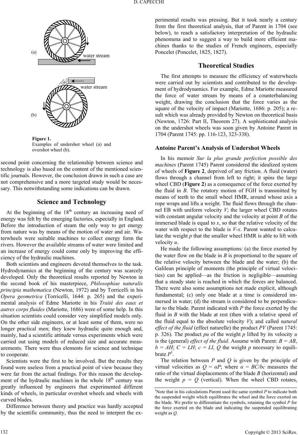
Probably the most important of the early engines which utilized water power was the vertical waterwheel. Its two basic forms are the undershot and the overshot. The undershot vertical wheel rotated in the vertical plane and had a horizontal axis. It normally had flat radial blades attached to its periphery and derived its motion from the impact of water flowing under the wheel and against these blades. While capable of working on any convenient stream without mill races (narrow artificial water channels, it worked most effectively in a race and with a stable volume of water running at a fairly high velocity. [Stronger than a Hundred Men: A History of the Vertical Water Wheel by Terry S. Reynolds Baltimore: The Johns Hopkins University Press, 1983.]
The Undershot Wheel worked in a running stream and could turn in shallow water. It was often built by the first settlers since it was relatively simple to set up … They were common in the early days when a dam could be built to compensate for dry periods … . [Mill: The History and Future of Naturally Powered Buildings by David Larkin. New York, 2000.]
The tub wheel could only work where the water flowed regularly throughout the year, and needed at least an eight-foot fall. The tub wheel was horizontal and was described as acted upon by percussion of water. The shaft is vertical, running the stone of top of it, and serves as a spindle. The water is shot on the upper side of the wheel in the direction of a tangent fitted with blades. It revolves in a sturdy tub, projecting far enough above the wheel to prevent the water from shooting over it, and whirls above it until it strikes the buckets. . [Mill: The History and Future of Naturally Powered Buildings by David Larkin. New York, 2000.]
The overshot vertical wheel was a much more efficient device. Water was fed at the top of the overshot wheel into “buckets” or containers built into the wheel’s circumference, and the weight of the impounded water, rather than its impact, turned the wheel. Each “bucket” discharged its water into the tail race at the lower portion of its revolution and ascended empty to repeat the process. The overshot wheel was usually more expensive than the undershot, since a dam and an elevated head race were normally required to build up a large fall of water and to lead the water to the wheel’s summit. It was suitable mainly to low water volumes and moderately high falls.
It is likely that the [emergence of undershot and overshot wheels] was at least partially influenced by several more primitive devices which tap the power of falling water – the water lever, the noria, and the primitive horizontal watermill. [Stronger than a Hundred Men: A History of the Vertical Water Wheel by Terry S. Reynolds Baltimore: The Johns Hopkins University Press, 1983.]
The overshot wheel required a dam above it so that the weight of water falling on it would make it turn. After one-third of a revolution, the water was spilled from the wheel. The water first striking the wheel gave it momentum, but the weight of the water in its buckets kept it turning. [Mill: The History and Future of Naturally Powered Buildings by David Larkin. New York, 2000.]
The difference between the pitch-back and the overshot wheels is that the trough stops shorter here and pours the water onto the wheel before the top of the wheel, or ‘on the near side’ as the millwrights used to say. The result therefore is that the wheel revolves in the opposite direction from the overshot, i.e. towards the flume or head-race. The buckets face in the opposite direction and the water therefore falls off at the same side as that on which it was received. [British Water-Mills by Leslie Syson. London, 1965]
The breast wheel, like the undershot wheel, turned in the opposite direction to the overshot wheel and received water above its center shaft at the nearest point of the water supply, and revolved easily because it was less loaded with water. . [Mill: The History and Future of Naturally Powered Buildings by David Larkin. New York, 2000.]
The flutter wheel was used when there was a large supply of water. It was small, low and wide—about three feet in diameter and up to eight feet wide. It got its attractive name from the sound it made. As the wheel went around, the blades cut through the entering water, making a noise like the fluttering wings of a bird. It was used almost entirely to power early sawmills. . [Mill: The History and Future of Naturally Powered Buildings by David Larkin. New York, 2000.]
The turbine with its curved blades, eventually replaced the waterwheel [in the mid-nineteenth century]. … Roy S. Hubbs pointed out that older undershot waterwheels presented a flat blade for the incoming water to impact, allowing half of the velocity to pass through unchecked. The Poncelet design [and the later resulting turbine] presented a curved blade with its lip angled tangentially to the incoming water … Benoit Fourneyron turned the wheel on its side and dropped the water into its center, allowing the water to flow simultaneously out of all the passages between the blades. … Since the turbine used all the openings between its blades simultaneously, it could be made much smaller. It turned much faster than the larger wheels. . [Mill: The History and Future of Naturally Powered Buildings by David Larkin. New York, 2000.]
Operating on the seesaw principle, the water lever utilized the power of falling water, but without the continuous rotary motion of water wheels. One end of a pivoted beam was equipped with a spoon-shaped bucket. On the other end was a hammerlike counterweight used for pounding or crushing. Water was directed into the bucket from a falling stream; the bucket filled, overweighed the hammer, and lifted it. The ascent of the bucket caused the water to spill; the hammer than overbalanced the bucket and fell. The cycle was then repeated to produce a steady pounding action.
The noria used for raising water, was form of undershot water wheel, but it activated no machinery (such as gears or millstones) beyond itself. It was simply a large vertically situated wheel, sometimes as much at 50-80 feet in diameter, equipped with radial blades which rotated the apparatus as they were impacted by the flowing water in which the lower portion of the wheel was immersed. Buckets of wood, bamboo, or pottery were attached to the rim of the wheel. As the device rotated, they were filed with water at the bottom of the wheel; the water was carried upwards in the buckets and emptied near the top of the wheel into a trough. The buckets were the returned empty to the bottom of the wheel to repeat the process.
Through all of antiquity and on into the early Middle Ages almost the only work to which the force of falling water was applied was grinding wheat. This was always to be one of its more important functions. But by the tenth century, European technicians had begun to adapt the vertical water wheel to other tasks. By the sixteenth century, in addition to flour mills, there were hydropowered mills for smelting, forging, sharpening , rolling slitting, polishing, grinding, , and shaping metals. Water wheels were available for hoisting materials and for crushing ores. There were mills for making beer, olive oil, poppy oil, mustard, coins, and wire. Water wheels were used in the preparation of pigment, paper, hemp, and tanning bark, and for fulling, sawing wood, boring pipes, and ventilating mines.

Water has been used to power simple and complex mills since antiquity. In colonial America, mills were powered by wooden waterwheels, but as technologies and manufacturing changed during the 19th century, water turbines began to be used more and more. In the period of 1850-1880 dozens of American manufacturers made cast iron turbines of nearly every conceivable configuration. Turbines could be readily ordered in different sizes that were suited for the specific water flow, shafting, and gearing needed for a particular mill. Turbines aren’t as susceptible to reduced flow when the water levels in the turbine pit are high or flooded. Perhaps best of all, turbines were iron and therefore did not require constant repair of a wooden waterwheel that began to rot from intermittent soaking even before installation was complete.

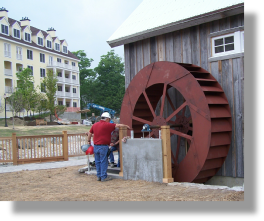
Some time around 1906, mill owner Allen Simmers replaced the old wooden water wheel with this steel water wheel manufactured by the Fitz Water Wheel Company of Hanover, Pa., which pioneered the mass production of steel wheels. These were more efficient than wooden wheels due to their curvilinear buckets, which held the water longer during the rotation of the wheel and thus increased its gravitational power. More than 16 feet in diameter, the wheel at the Mill at Anselma produces 6,400 foot pounds of torque-equivalent to 13 Lamborghini sports cars. At full power it moves 2,000-3,000 gallons of water per minute.

Power wheels, the overshot in particular, benefits from several often overlooked design features. Operational reliability and ruggedness are very high in a practical installation, the overshot tolerates heavily silted waters, flood debris, rocks, rubbish and outright vandalism. The high rotational inertia and increased static torque create a self cleaning mechanism that breaks tangled fishing lines and carrier bags. Fish and all aquatic life are completely unaffected and water quality may be slightly improved.
The overshot and midshot wheels are very much more efficient than often stated, indeed the overshotis the most efficient energy extractor for limited applications. We make hese to any size; Our Ultra Ultra low head midshots operate in impossibly low head situations finding great favour with utilities and agencies for continuous small or transient high power demands.
Water wheel design has evolved over time with some water wheels oriented vertically, some horizontally and some with elaborate pulleys and gears attached, but they are all designed to do the same function and that is too, “convert the linear motion of the moving water into a rotary motion which can be used to drive any piece of machinery connected to it via a rotating shaft”.
Early Waterwheel Design were quite primitive and simple machines consisting of a vertical wooden wheel with wooden blades or buckets fixed equally around their circumference all supported on a horizontal shaft with the force of the water flowing underneath it pushing the wheel in a tangential direction against the blades.
These vertical waterwheels were vastly superior to the earlier horizontal waterwheel design by the ancient Greeks and Egyptians, because they could operate more efficiently translating the hydrokinetic energy of the moving water into mechanical power. Pulleys and gearing was then attached to the waterwheel which allowed a change in direction of a rotating shaft from horizontal to vertical in order to operate millstones, saw wood, crush ore, stamping and cutting etc.
Most Waterwheels also known as Watermills or simply Water Wheels, are vertically mounted wheels rotating about a horizontal axle, and these types of waterwheels are classified by the way in which the water is applied to the wheel, relative to the wheel’s axle. As you may expect, waterwheels are relatively large machines which rotate at low angular speeds, and have a low efficiency, due to losses by friction and the incomplete filling of the buckets, etc.
The action of the water pushing against the wheels buckets or paddles develops torque on the axle but by directing the water at these paddles and buckets from different positions on the wheel the speed of rotation and its efficiency can be improved. The two most common types of waterwheel design is the “undershot waterwheel” and the “overshot waterwheel”.
The Undershot Water Wheel Design, also known as a “stream wheel” was the most commonly used type of waterwheel designed by the ancient Greeks and Romans as it is the simplest, cheapest and easiest type of wheel to construct.
In this type of waterwheel design, the wheel is simply placed directly into a fast flowing river and supported from above. The motion of the water below creates a pushing action against the submerged paddles on the lower part of the wheel allowing it to rotate in one direction only relative to the direction of the flow of the water.
This type of waterwheel design is generally used in flat areas with no natural slope of the land or where the flow of water is sufficiently fast moving. Compared with the other waterwheel designs, this type of design is very inefficient, with as little as 20% of the waters potential energy being used to actually rotate the wheel. Also the waters energy is used only once to rotate the wheel, after which it flows away with the rest of the water.
Another disadvantage of the undershot water wheel is that it requires large quantities of water moving at speed. Therefore, undershot waterwheels are usually situated on the banks of rivers as smaller streams or brooks do not have enough potential energy in the moving water.
One way of improving the efficiency slightly of an undershot waterwheel is to divert a percentage off the water in the river along a narrow channel or duct so that 100% of the diverted water is used to rotate the wheel. In order to achieve this the undershot wheel has to be narrow and fit very accurately within the channel to prevent the water from escaping around the sides or by increasing either the number or size of the paddles.
The Overshot Water Wheel Design is the most common type of waterwheel design. The overshot waterwheel is more complicated in its construction and design than the previous undershot waterwheel as it uses buckets or small compartments to both catch and hold the water.
These buckets fill with water flowing onto the wheel through a penstock design above. The gravitational weight of the water in the full buckets causes the wheel to rotate around its central axis as the empty buckets on the other side of the wheel become lighter.
This type of water wheel uses gravity to improve output as well as the water itself, thus overshot waterwheels are much more efficient than undershot designs as almost all of the water and its weight is being used to produce output power. However as before, the waters energy is used only once to rotate the wheel, after which it flows away with the rest of the water.
Overshot waterwheels are suspended above a river or stream and are generally built on the sides of hills providing a water supply from above with a low head (the vertical distance between the water at the top and the river or stream below) of between 5-to-20 metres. A small dam or weir can be constructed and used to both channel and increase the speed of the water to the top of the wheel giving it more energy but it is the volume of water rather than its speed which helps rotate the wheel.
Generally, overshot waterwheels are built as large as possible to give the greatest possible head distance for the gravitational weight of the water to rotate the wheel. However, large diameter waterwheels are more complicated and expensive to construct due to the weight of the wheel and water.
When the individual buckets are filled with water, the gravitational weight of the water causes the wheel to rotate in the direction of the flow of water. As the angle of rotation gets nearer to the bottom of the wheel, the water inside the bucket empties out into the river or stream below, but the weight of the buckets rotating behind it causes the wheel to continue with its rotational speed.
Once the bucket is empty of water it continues around the rotating wheel until it gets back up to the top again ready to be filled with more water and the cycle repeats. One of the disadvantages of an overshot waterwheel design is that the water is only used once as it flows over the wheel.
The Pitchback Water Wheel Design is a variation on the previous overshot waterwheel as it also uses the gravitational weight of the water to help rotate the wheel, but it also uses the flow of the waste water below it to give an extra push. This type of waterwheel design uses a low head infeed system which provides the water near to the top of the wheel from a pentrough above.
Unlike the overshot waterwheel which channelled the water directly over the wheel causing it to rotate in the direction of the flow of the water, the pitchback waterwheel feeds the water vertically downwards through a funnel and into the bucket below causing the wheel to rotate in the opposite direction to the flow of the water above.
Just like the previous overshot waterwheel, the gravitational weight of the water in the buckets causes the wheel to rotate but in an anti-clockwise direction. As the angle of rotation nears the bottom of the wheel, the water trapped inside the buckets empties out below. As the empty


 8613371530291