
reverse overshot water wheel pricelist

We have a number of options for coating a metal water wheel. We will thoroughly discuss your plans with you and recommend the best coating solution. Please see our section on Wheel Coating Options.
Site Installation:With water wheels that are eight feet or more in diameter, we suggest that we provide our personnel to help with the site installation. Smaller wheels generally can be assembled at the site and installed by your personnel. We cannot guarantee assembly if we are not there for the installation.
Shipping: We ground ship throughout the United States. Our engineering associate in Italy is prepared to supervise assembly and installations overseas. We negotiate the best price and reliable logistics management for timely delivery of your waterwheel to your installation site.
The Waterwheel Factory closely collaborates with Designers, Mill Owners, Architects, Property Developers, General Contractors and Property Owners on a personal basis to assure that each water wheel project is optimally managed from conception to final installation.
Send us your buildings CAD drawings and we will work with them to include the details needed to support your waterwheel for you, your builder and permit office.
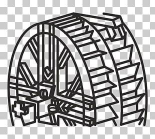
Frequently used in mines and probably elsewhere (such as agricultural drainage), the reverse overshot water wheel was a Roman innovation to help remove water from the lowest levels of underground workings. It is described by Vitruvius in his work
The Roman author Vitruvius gives explicit instructions on the construction of dewatering devices, and describes three variants of the "tympanum" in Chapter X of
Pliny the Elder is probably referring to such devices in a discussion of silver/lead mines in his silver in his time, many of the silver mines having been started by Hannibal. One of the largest had galleries running for between one and two miles into the mountain, "water-men" (in Latin "aquatini") draining the mine, and they
That they stood suggests that they operated the wheels by standing on the top to turn the cleats, and continuous working would produce a steady stream of water.
Fragments of such machines have been found in mines which were re-opened in the Victorian era in Spain, especially at Rio Tinto, where one example used no less than 16 such wheels working in pairs, each pair of wheels lifting water about 3.5 metres (11 ft), so giving a total lift of 30 metres (98 ft). The system was carefully engineered, and was worked by individuals treading slats at the side of each wheel. It is not an isolated example, because Oliver Davies mentions examples from the Tharsis copper mine and Logroño in Spain, as well as from Dacia. The gold deposits in Dacia, now modern Romania were especially rich, and worked intensively after the successful Roman invasion under Trajan. According to Oliver Davies, one such sequence discovered at Ruda in Hunedoara County in modern Romania was 75 metres (246 ft) deep. If worked like the Rio Tinto example, it would have needed at least 32 wheels.
One such wheel from Spain was rescued and part of it is now on display in the British Museum. Some of the components are numbered, suggesting that it was prefabricated above ground before assembly in the underground passages. In the 1930s, a fragment of a wooden bucket from a drainage wheel was found in deep workings at the Dolaucothi gold mine in west Wales, and is now preserved in the National Museum of Wales in Cardiff. It has been carbon dated to about 90 AD. From the depth of 50 metres (160 ft) below known open workings, it can be inferred that the drainage wheel was part of a sequence just like that found in Spain. The shape of the edge of one of the lifting buckets is almost identical with that from Spain, suggesting that a template was used to make the devices.
They were also used in series, so increasing the lift of water from the workings. However, they must have been more difficult to operate since the user had to stand on a slanting surface to turn the screw. The steeper the incline, the greater the risk of the user slipping from the top of the screw. No doubt the reverse water wheel was easier to use with a horizontal treading surface. On the other hand, the screw could be operated by a crank handle fitted to the central axle, but would be more tiring since the weight of the operator does not bear on the crank, as it does when trod from above.
Like the reverse water wheel, the cochlea was used for many other purposes apart from draining mines. Irrigation of farmland would have been the most popular application, but any activity which involved lifting water would have employed the devices.
Multiple sequences of water wheels were used elsewhere in the Roman Empire, such as the famous example at Barbegal in southern France. This system was also a stack of 16 wheels but worked like a normal overshot wheel, the wheels driving stone mills and used to grind grains. The water mills were worked from a masonry aqueduct supplying the Roman town at Arles, and the remains of the masonry mills are still visible on the ground today, unlike the underground drainage systems of the mines, which were destroyed by later mining operations. Other such sequences of mills existed on the Janiculum in Rome, but have been covered and changed by later buildings built on top of them.

Back in 1947, Popular Science printed a five-part article by C.D. Bassett that very concisely sketched out every step necessary for the establishment of a small water-power plant on a farm or homestead. That information is still just as valuable today for many of MOTHER’s readers as it was 30 years ago . . . and that’s why THE MOTHER EARTH NEWS asked for — and received — permission to reprint the whole series as a two-part article in MOTHER NOs. 13 and 14. The Popular Science material was also included — by permission — in THE MOTHER EARTH NEWS Handbook of Homemade Power.
If any of the terms or ideas in the accompanying article are unfamiliar to you, then, you have three choices: [1] You can trot on down to your local library and exhume the old, original C.D. Bassett articles from the 1947 issues of Popular Science, [2] you can order out MOTHER NOS. 13 and 14 at $2.00 apiece from the ad on pages 114-115 of this issue, or[3] you can get your own copy – $1.95 plus 75¢ shipping and handling — of The Handbook of Homemade Power by using the MOTHER’s Bookshelf ad on pages 174 -177 of this issue. Any way you go about it, you’re going to learn all you need to know to lay out, install, and operate your own water-power system. All you’ll need to add to this information is a free-flowing stream . . . and you’re in business.
One final note: The following article describes a homemade overshot water wheel set up to do only one thing . . . pump water from a spring to a set of farm buildings 100 feet above. If you’re more interested in learning how to use the same kind of wheel to generate electricity, see the article, schematic drawing, and photographs of Thomas Oates’ water-wheel powered DC electrical system in MOTHER NO. 24. That piece was also reprinted in The Handbook of Homemade Power. — The Editors.
One very successful example of this “back to basics” trend is the water wheel-powered water pump now in operation on the Robert Wooding farm near Halifax, Virginia. The pump-powered by a home designed and home-built 6 1/2-foot, steel water wheel which, in turn, is spun by water from a stream on the family farm shoves 1,440 gallons of pure spring water 100 feet uphill every 24 hours. And, since the system was set up, it hasn’t cost the Woodings anything for its tireless round-the-clock operation . . . except a few cents for lubrication.
“There are three things I especially like about my wheel,” says Bob blooding. “One, unlike the hydraulic ram pumps featured several times in MOTHER, it doesn’t use gallons and gallons of our drinking water just to pump a few gallons up the hill. Two, the overshot design of our wheel makes very efficient use of the small stream we tap for power. And, three, there’s not a whole lot of banjo work to a rig like this once you’ve got it going. We spent a little time and money setting our system up, to be sure, but it’s been practically maintenance-free ever since. About all we do is give its bearings a shot of grease two or three times a year.”
The Woodings were fortunate enough to have a picturesque stream on their property (the first and most obvious requirement for any water-power system!) . . . but that’s as far as their luck went. At no single spot along the creek was there enough “fall” to turn the 6 1/2-foot overshot wheel that Bob figured on installing.
Fall, as the name implies, is the amount of vertical distance that running water drops as it moves down a stream (if there were no fall at all, the water — obviously — wouldn’t run and the stream wouldn’t be a stream . . . it would be a slough or a lake).
The ideal location, of course, for an overshot water wheel (which must be positioned in a stream at a spot where the water abruptly drops at least as far as the wheel is tall) is a natural rapids or waterfall. If, like the Woodings, you find yourself working with a stream that has no such abrupt natural drop, however, you’ll have to do what the Woodings did: Build your own man-made waterfall . . . which, as we all know, is commonly called a dam.
(NOTE: The reprinted series of five articles from Popular Science mentioned at the beginning of this piece contains everything you need to know to calculate the flow and call of a stream, design several kinds of dams, build and install an overshot wheel, and otherwise fabricate and operate a farm- or homestead-sized water-power system. — The Editors.)
“We needed about a seven-foot fall for our 6 1/2-foot-tall wheel,” Bob blooding remembers, “so we built a three-foot-tall dam . . . and then flumed the water from the top of that dam to a spot 120 feet further downstream where the creek’s banks were an additional tour feet lower. The dam’s height of three feet plus the additional four feet of drop we picked up by running our flume that tar added up to the seven feet of fall, or head, that we needed for our wheel.”
The Woodings’ flume is a combination of approximately 85 feet of four-inch aluminum pipe feeding into an additional 46 1/2 feet of wooden trough measuring six inches deep by six inches wide. (The aluminum pipe, which extends about a foot and a half into the trough, can be lifted out and set into a curved metal deflector which routes its water back into the stream whenever the Woodings want to stop the wheel.)
Traditional flumes for homestead water wheels, of course, were of all-wood construction. But Bob Wooding decided to use rot-free, corrosion-free aluminum pipe for the first two-thirds of his wheel’s feeder line, where the flume had to extend into the water and then run underground. The pipe’s inlet is covered with a screen to keep the line from becoming clogged with misguided leaves, turtles, and crawfish. Care was also taken to position the opposite (wooden) end of the flume so that its discharge of water would hit the exact top-center of the overshot wheel.
Although the blooding family’s water system for their house, stables, and swimming pool is powered by the stream on their farm . . . the actual water which flows through that system comes from a clear, cool, pure spring. This spring, too (just like their dam), is located about 120 feet from the overshot wheel and pump that is the heart of the whole hookup. So, in addition to the flume which carries the “driving” water from the dam to the wheel, another one-inch pipe was laid to carry the “driven” water from the spring to the pump that is installed next to (and driven by) the wheel.
Luckily for the Woodings, the spring water’s temperature stays 52 degrees Fahrenheit year round. Merely by laying this feeder pipe so that it has a continuous slight grade from the spring down to the pump a few feet below, then, the family has been able to keep their water supply from freezing in the winter without going to the trouble of burying the pipe below the frost line.
When you buy a manufactured water wheel, a large portion of the purchase price goes to pay for the equipment’s design. It follows, then, that you can save yourself a sizable chunk of cash by working up the specifications for your own wheel . . . and that’s exactly what Bob Wooding did.
Actually, this isn’t as difficult as you might think. To extract maximum power from any given flow of water with an overshot wheel is largely a matter of calculating the proper depth and angle of the buckets placed around the wheel’s rim (ideally, each bucket must be completely filled at top center and then carry its load of water without spilling a drop until just the instant it passed bottom center . . . but anything even remotely approaching this ideal will handle the job satisfactorily in most homestead applications).
(EDITORS’ NOTE: If you scale up the drawings shown here and use them to construct a wheel ranging anywhere from two feet up to 20 feet in diameter — and if you work carefully and in a craftsman-like manner — the chances are good that your finished wheel will work well enough to make you pretty dang proud of yourself. If you really want to go for the finer points of maximum efficiency, however, you can work from the more detailed dimensions and angles given in the full-page drawing of an overshot wheel on page 31 of MOTHER N0. 14.)
After drawing up his design (complete with “dribble” hole in the bottom of each bucket, so that the wheel is self-draining when not in use!), Bob had the individual parts for his water wheel prefabbed by the Carolina Steel Company in Greensboro, North Carolina. A Richmond, Virginia representative for the firm says that the 3/16 inch steel plate used in the 980-pound assembly’s 37 eight-by-twelve-inch buckets, its five-inch-wide rim, and its one-foot-wide sole plate would currently cost about $130. You can add on another $70 for burning, forming, and welding the metal. (These prices, of course, will vary in different parts of the country and — as time goes on — are sure to escalate right along with the price of everything else.)
The hubs for the Wooding wheel were pretty much “Chinese copied” from the hubs manufactured years ago by the now-defunct Fitz Water Wheel Company of Hanover, Pennsylvania. Bob had them cast at a local foundry from a wooden pattern that he made himself, and the materials and labor for the raw castings set him back only $25. A nearby machine shop then bored out the hubs on a lathe, cut keyways into the bores, and made up the pair (each half of the set contains six 3/8 inch by 2 inch spokes) of spokes for the wheel . . . all for only $60 complete.
Once he had all the components for his wheel prefabbed and in hand, there was nothing for Bob Wooding to do but assemble the power unit. “I used calipers to measure and remeasure the spaces around the rim for my buckets until I had them exact to the width of a pencil mark,” Bob says. “Then I tacked the buckets in place all the way around and rechecked everything before I finally welded them in permanently. If you try to finish-weld each one as you go without tacking everything together first, you know, you can get off kilter and warp the whole wheel.”
Every one of the six “ears”, or extensions, on each of the two hubs has a recessed area 3/8 inches deep by two inches wide by four inches long on its inside surface for a spoke to set into. This end of each spoke is held firmly in place with two 7/16 inch galvanized bolts, nuts, and lock washers. The other ends of the spokes are welded to the outside faces of the wheel’s rim . . . as you can see in one of the accompanying photos.
It should also be pointed out that the distance (16 inches) between the two hubs is four inches wider than the distance (12 inches) across the buckets on the rim. This “dish” effect — so typical of the Fitz wheels of years ago — adds a great deal of strength to the completed wheel . . . without adding any additional weight.
The finished wheel was hoisted with a front-end loader, hauled to the foundation that had been poured for it, and gently eased down until the pillow block bearings on its two-inch steel shaft could be bolted into place. A few small pieces of metal were then welded into some of the buckets to balance the completed assembly, and the whole wheel was given a primer coat of zinc chromate and a finish coat of black enamel.
As water pours down over one side of the mounted wheel and turns it, the spinning of the wheel is converted to an up-and-down pumping motion by an eccentric arm attached to the assembly’s two-inch-thick main shaft. This “arm”, to be truthful, is not really an arm at all . . . but simply a spot one and a half inches off center on the face of a 15-inch gear salvaged from a local junkyard. The spot has been drilled and tapped to accept a threaded mounting pin for the lower end of a long white oak connecting rod.
As the water wheel’s main shaft rotates, then, the 15-inch gear attached to it also rotates smoothly. This causes the eccentric pin fastened to the face of the gear to revolve around and around in a three-inch arc. Which, in turn, causes the guided white oak connecting rod that rides the pin to pump up and down with a three-inch stroke.
The upper end of the connecting rod (think of it as the hand holding the handle of an old-fashioned “armstrong” water pump) is bolted to a cross-arm that runs across the top of a reservoir and is secured to a red cedar post on the other side so that it can hinge up and down. And in the middle of that cross-arm — just off center in favor of the water wheel — is attached a cylinder rod which runs down to a cylinder pump that is firmly bolted to the bottom of the reservoir.
And that’s all there is to the Wooding stream-run, spring-fed water system. Water from the spring 120 feet away runs a couple of feet downhill to fill the cement reservoir. At the same time, a great deal more water from the dam — also about 120 feet away but in a slightly different direction — flows through the flume and pours down over one side of the 6 1/2-foot water wheel, causing it to turn. And, as the wheel turns, the pump in the reservoir pumps . . . which forces the fresh spring water 100 feet uphill (through a line buried beneath the frost line) to a 500-gallon storage tank which stands near the blooding house. And, from that tank, the spring water is then gravity-fed to the house, stables, and swimming pool on the blooding property.
And there’s something rather nice about the whole arrangement. The “splash-splosh” of the water wheel is far more relaxing and natural than any huffing-puffing engine . . . and a lot less expensive to operate year in, year out than any quiet but increasingly costly electric motor. Every bit of technology used in the Wooding setup, of course, has been around a long, long time . . . and a lot of other farmsteads in the country could put a variation of the same idea into use right now.
The path that the water takes through a turbine and the general layout is often used for classification, like tangential-flow, radial-flow cross-flow and axial-flow. Below are the various categories of ‘water driven prime mover that can be used to convert the ‘potential energy’ in a river or stream into usable ‘mechanical’ or ‘electrical’ energy. This section continues with information on what types of turbine are suitable in various sites and applications.
Gravity devices are those where any kinetic energy present at the entry of the device is either minimal or lost in turbulence and does nor contribute measurably to the output of the device. Such devices include most waterwheel types, Archimedes screws (where the outer case rotates with the flutes); Hydrodynamic screws (as used for sewage pumping and now being used in reverse as low-head prime-movers); Norias (more commonly used for raising water) and consist of a string of buckets like an overshot waterwheel attached to form a chain, and positive displacement devices or hydraulic engines.
Impulse turbines are those where the potential energy in a ‘head of water’ is largely converted into kinetic energy at a nozzle or spout. The simplest of such devices is the Gharat or Norse Wheel (where the conversion to kinetic energy takes place in an open flume). The more conventional devices harness the potential energy in a pipeline or penstock that terminates in a nozzle. The flow path through the turbine is usually used to describe the specific device, namely, tangential-flow, radial-flow, cross-flow, axial-flow or mixed-flow. Specific turbine designers have been associated with most of these devices, though confusion can result because they often designed several different types of device (The Pelton Waterwheel Company also made cased reaction turbines, Herschel pre dates Jonval’s patent that was the precursor of the Turgo Impulse wheel, a single nozzle version developed by Gilkes. Donat Banki, a Hungarian was also making cross-flow turbines many years before Mitchell and Ossburger came on the scene.
Reaction turbines are those where the turbine runner is usually completely flooded and the transfer of energy from the water to the turbine runner is achieved by a combination of reaction and/or lift. Some designs of cross-flow turbine in common use a combination of impulse and reaction. Reaction turbines have had a more complex development, with many designers and factories adding features such as movable ‘wicket gates’ that resulted in Francis’s name becoming the tag by which this group of turbines are now known. The Kaplan turbine developed in the 1930s is a sophisticated variable geometry version of the ‘propeller turbine’ that as its name suggests is similar to a ship’s propeller in a housing. Halfway between these types is the single regulated propeller turbine, where either the runner blades or the ‘guide vanes’ (wicket gates) are adjustable.
Free-stream devices encompass large slow running wheels and turbines, some of which are being tried out for marine energy applications. Like wind turbines, the power delivered increases as a cube of the velocity, such that a doubling of the velocity gives an eight fold increase in power output. The devices themselves are very large and slow running and only have very specialised applications for extracting small amounts of power from bank-side locations on very large rivers.
High head sites with over 20 metres of fall, where the water is conveyed directly to the turbine in a pipe (penstock) or via an open canal followed by a piped section, generally use impulse turbines. The reason is that high head sites are usually subject to significant changes in water flow and reaction turbines like the Francis are not able to cope with such variations. Silt in the water can also cause a lot of damage to Francis turbines that is expensive to repair.
One of the most successful high head turbines was developed in California during the gold rush from a device referred to as a ‘hurdy gurdy’ that was basically a cartwheel with buckets around the periphery. A carpenter by the name of Lester Pelton came up with the now familiar double bucket shape and went on to found ‘The Pelton Watewheel Company’ of San Francisco. The bucket design was later improved by Doble who joined the company as an engineer in 1899. Doble’s improvement is the central cut-out in the bucket that prevents the water jet from first striking the back of the bucket and wasting energy. www.oldpelton.net. Today, similar machines are operating from over 1000 metres of fall and generating up to 100MW of power.
A simple weir is all that is required to divert the stream into the penstock (pipeline) via a de-silting chamber to remove any sand. Water storage may be included if the terrain allows and if it is advantageous to generate more power for short periods or where it is necessary to store water for generation when flows are very low. A low-pressure pipe or open canal may also be used to reduce to overall cost if it allows a short steep decent to the powerhouse using less high-pressure pipe.
Pelton turbines are efficient over a very wide range of flows but at lower heads the speed is too low for belt drives, so we reduce the pitch circle and modify the bucket shape to increase the specific speed. The jets may have plain nozzles or adjustable spear valves to adjust the water consumption to the available stream flow. It is usual with larger machines to have ‘deflectors’ that divert the water away from the runner for controlling the speed without altering the water flow. They can also be used for emergency shutdown.
For thousands of years waterpower has been harnessed for milling and pumping water. In the Developing World many are still in daily use, but in Western Countries they have usually fallen into disrepair as a result of competition from diesel and electric power. In the U.K. there were over 70,000 working mills at the end of the 18th century and now there are a few hundred. These mills fall into a number of categories that will determine their suitability for redevelopment.
The waterwheels that were used on these sites in the U.K. are usually of the Roman or horizontal shaft type, though the vertical shaft type is much more common in Mediterranean and Asian countries. Depending on the fall of water available, the horizontal wheels are classified into ‘Overshot’, ‘Breast-shot’, ‘Back-shot’ and ‘Under-shot’. With the exception of projects to restore a mill to its original design, or where the visual appearance is important to maintain, only the overshot wheel is suitable for a new power generation projects.
Overshot waterwheels are the most fish-friendly and able to handle leaves and sticks. A similar device is the Noria or chain wheel, which has the disadvantage of potential more maintenance, but it runs faster, is more efficient and easier to install than an overshot waterwheel.
The power available is a function of the head and flow so building a large wheel will only increase the cost and reduce the shaft speed but not increase the power. Major components in the cost are the primary gearbox and the material required in the construction of the wheel itself. We are happy to build any type of waterwheel, but the cost is likely to be significantly greater than that of an equivalent turbine, when you take the gearing and installation costs into consideration. There are no short cuts with waterwheels and the engineering has to be good, on account of the high torque in the low speed drive.
Mills with ponds are seldom suitable for redevelopment for anything other than a few kilowatts because the water flow is obviously too little to sustain the mill on a continuous basis, and it is much too expensive to install a wheel or turbine that can only be operated for a few hours a day. In some cases the ponds were only used in the summer months when the water was low, but today we are looking to the higher winter flow for the bulk of the power that can be used for heating. There is always a loss of head into and out of the pond, but this may be recoverable with a turbine installation.
Mills with leats, lades or channels take their water from a water course along the side of a valley at a gradient that is usually less than one in five hundred. At a suitable point when enough fall can be achieved in one place, the mill is built. The only limitations to future development are the actual head and flow available. Since there was a mill there anyway there should be enough power for domestic purposes. Improvements to the leat and head are usually possible but are very site specific. Modern mini excavators make leat widening and maintenance much easier than when the mills were first built.
Mills on weirs or with short wide diversion channels present the most difficult challenge for the developer. The available head may only be a metre or so and the flow required to generate useful amounts of power will be several cubic metres of water per second. The undershot waterwheels that were originally used at these sites are totally redundant on account of their high cost and low efficiency. The exact layout of the site becomes increasingly important with the lower falls, because access for excavators and to install the large items of equipment is more difficult.
Open flume installations are the most usual for the very low head sites, and employ fixed geometry propeller turbines on account of their simple construction and high ‘specific speed’. The more complex variable ‘Kaplan’ type turbines are not economic for these small schemes and it is easier to achieve ‘flow control’ by installing more than one machine or by running until the water has fallen by say 100mm and then switching off automatically until it has come up again. This latter system can be used for heating
Tubular turbines of the propeller type can be used for mill sites with a higher head, typically those that originally employed ‘Overshot’ waterwheels. Many different arrangements are possible to suite existing civil works but the main compromise arises from their inflexible performance. If the mill is only extracting a small percentage of the available water from the main river, then there is no problem. If however the water flow reduces below that which is required to supply the turbine, either water storage, another smaller turbine or a change in turbine speed will be required.
Archimedes Screws have come into the news in recent years because of their reported fish friendliness, but firstly the units being described are NOT Archimedes screws but Screw pumps running in reverse (hydrodynamic screws) and secondly the hydrodynamic screws are not as friendly as they might first appear. The difference in respect to fish friendliness is potentially significant since the true Archimedes screw has its outer casing rotating with the screw flights so that no fish, eel or lampray can be killed or injured by getting caught in the gap or abraded against the concave that will undoubtedly become rough with time and damage.
Low cost open impulse turbineshave been developed by us, primarily for projects in the Developing World. Installed outside the mill house like a waterwheel, it is an economic alternative for smaller domestic sites here in the U.K. They cannot be used with a draft tube since the runner is open to the atmosphere but the installation and maintenance is much simpler. The valve control shaft is extended through the mill house wall to an operating lever on the ,inside or a simple open shoot conveys the water directly to the runner in the manner of the old ‘flutter wheels’ used in the USA in the 19c. Installation work is usually kept to a minimum and may be in an old waterwheel pit or even behind an existing wheel under the launder. A vertical shaft version like the Indian Gharat can produce considerably more power by increasing the entry area, whilst maintaining its self-cleaning characteristics.
Portable turbines are highly adaptable and be assembled on site in a few hours. Applications include ‘Rural Development’, camping and field hospitals. Typical outputs range from 200 watts to 50 kW. The inlet works are prefabricated and the pipeline is either flexible polyethylene or ‘lay-flat’ coiled pipe. The whole unit can be built into a trailer or air-portable unit for rapid deployment in the field. The buckets that are divided along their centre line by a splitter ridge, turn the jet of water that is directed at them, through 1800 so that the energy is transferred efficiently to the shaft.
Turbines that are suitable for a particular type of site and turbines that are suitable for particular type of application are referred to as ‘groups’. Hence you can have a group of ‘Hillstream’ turbines for upland sites, or a group of ‘Agricultural’ turbines for agricultural applications. The site may be defined topographically as an upland or ‘Hillstream’ site, or as a lowland or ‘Millstream’ site. Each of these groups I then divided into two sub-groups depending on the actual site layout and general features. The ‘Hillstream’ group is comprised of vertical and horizontal shaft impulse turbines that may be either direct drive, belt drive or overhung from the generator. The application for the plant may be to generate electricity, mechanically power machinery or pump water for irrigation or for a drinking water supply. The application will also have a bearing on the materials, the sophistication, the governing system and the general build.

Water wheels are generally perceived as being inefficient energy converters which belong to the past, with no role for the future. But as Gerald Müller, Klemens Kauppert and Rüdiger Mach explain, they can actually be efficient and cost-effective in low head micro hydro applications
IN EUROPE, a large number of low head micro hydro power sites (head = <5m, power = <100kW) exist. Water power was a prime power source during the industrial revolution and thousands of water mills were built at low head sites. Today however, the large majority of such hydro power sources is not exploited due to the lack of a cost-effective hydraulic power converter. Recently, a number of developments appear to have opened up the possibility to generate electricity economically at low head sites. These developments include the two oldest hydraulic machines, namely water wheels and the Archimedian screw - the latter working in reverse as a power source rather than as a pump.
Water wheels are today often considered to be relics from the beginning of the industrial revolution; romantic but inefficient hydraulic machines made of wood and belonging to the past. It is generally believed that turbines are much more efficient than water wheels and subsequently took over their role as hydraulic power converters. The statistics however show a different picture. In Bavaria - a German province with an area of 70,500km2 - there were 7554 operational water wheels counted as late as 1927, with power outputs ranging from 0.75 to 75kW. In the middle of the 19th century, a high stage of development was reached when Zuppinger designed the most modern and efficient water wheel. Engineers, manufacturers and mill owners must have regarded water wheels as commercially interesting power sources. During the 1940s however, virtually all water wheels seem to have disappeared.
Today, some companies in Germany (Bega, Hydrowatt) and the US (Water Wheel Factory) are again manufacturing water wheels for electricity generation. The performance characteristics of such wheels still appear to be largely unknown. Assessment of the available power potential, comparisons with other turbine types such as the Kaplan or the Ossberger (crossflow) turbine, and even the determination of optimum operating conditions for water wheels, relies on estimates.
"Modern" water wheels, ie water wheels built using scientific principles, are made of steel and employ only the potential energy of the water since in low head flows the potential energy exceeds the kinetic energy of the flow by far. These water wheels can be divided into three fundamental types:
Water wheels were, in the large majority of cases, used to drive machinery and reached efficiencies of 75-89%. This development seems to have subsequently been forgotten.
In Karlsruhe, Germany, a small non-profit research company (IFMW - Institut für Forschung und Medien im Wasserbau) has been set up which specialises in hydraulic engineering research, and in particular in the development and promotion of low head hydro power. Within the company, a very detailed literature and market review on water wheels was conducted in order to assess the suitability of water wheels for electric power production. Since only over and undershot wheels are currently built, the discussion will be limited to those two types.
The overshot wheel receives its feeding water at the top of the wheel, catches the water in buckets or "cells" and releases the water at the lowermost possible elevation. In order to make maximum use of the energy contained in the water, the cells are shaped so as to receive the water at its natural angle of fall and then to retain it as long as possible.
Some measurements of the performance characteristics of overshot wheels were conducted in 1928, as shown in the figure below. It was found that the efficiency of a water wheel reaches 85%.
The undershot wheel was developed for the utilisation of very low heads from 0.5-2m. Whereas in ancient times the kinetic energy of the flow was utilised with a paddle-type wheel, "modern" undershot wheels built after Zuppinger"s design employ the potential energy only. The figure below shows a Zuppinger wheel with the typical "backwards" inclined curved blades.
Wheel diameters range from 4-7m, with head differences from 0.5 to 1.5m. The blades are arranged in a way so as to avoid losses at the water entry, then gradually reduce the head of water in each cell and finally to discharge the water, again with a minimum of losses. The wheel blades are curved to allow for a gentle decrease of the water level from upstream to downstream, and to minimise losses at the downstream end. In an engineering textbook from 1939 it was stated that efficiencies of 76% can be guaranteed for properly designed undershot wheels.
Recently, the undershot wheel has also experienced a small renaissance. Hydrowatt has built and installed 15 Zuppinger wheels over the last nine years, with diameters ranging from 4-7.5m, and widths of 0.5-3m. Hydraulic heads utilised ranged from 1-2.2m, with typical flow rates of 1.5-3.1 m3/sec, giving power outputs from 4-45kW of electrical power. The overall efficiency (from hydraulic power available to electric power out) was estimated as ranging from 60 to 65%.
In the UK, many smaller streams were made navigable by building weirs, many of which still exist. Generally, the head differences were in the range between 1.2-1.8m. The undershot wheel may offer a possibility to produce electric power from such weir sites. The picture below shows a typical weir situation (Eel weir on the Lagan river in Northern Ireland) with a virtual water wheel inserted. The water wheel actually fits into a "natural" environment very well, indicating that a modern machine can become a visually attractive feature too.
The Archimedian screw has been known since antiquity as a simple machine for the lifting of water. Today, Archimedian screws are still in widespread use as pumps for sewage, grain and so on. It has the advantage of being a very simple machine, with only one moving part and two bearings. It was however only recently noticed that the screw could also - in its reverse role - be employed as energy converter, termed hydraulic screw. Large scale experiments with a hydraulic screw of 8.6m length and 2.35m drop were conducted at Prague Technical University in the Czech Republic in order to assess the performance of the hydraulic screw in its power generation mode.
The screw shown in the picture above was designed for a maximum flow rate of Qmax = 0.35 m3/sec. In experiments, it reached an efficiency of 70% for Q/Qmax = 0.4, and 80% for 0.6 < Q/Qmax < 1.0. The screw rotates at 53rpm, so that fewer gear ratios than for a comparable water wheel are required to achieve the speed necessary for electricity generation. To the author"s knowledge, six hydraulic screws have been installed already. Some design guidance for hydraulic screws, based on the design experience with screw pumps and generator experiments, is also available.
The economics of micro hydro converters are a function of variable boundary conditions such as electricity prices and so on. In Germany, overshot water wheels are currently built (including installation and grid connection) for 4360-4850 US$/kW. Undershot wheels cost 7760-9700 US$/kW, Archimedian screws approximately 8250-8730 US$/kW installed capacity. For comparison, low head Kaplan turbines cost 14500-15500 US$/kW. Although water wheels and the Archimedian screw have significant cost advantages over turbines, micro hydro installations are economical only if the owner uses the generated electricity at least partially, such as for a small business. Assuming 50% of self use, 6000 hours of operation per year at nominal capacity, a small business electricity price of 11 c/kWh and a price of 7.3 c/kWh for electricity fed into the grid, the following pay back periods apply:
The general perception amongst the public as well as many engineers is that water wheels are inefficient energy converters and belong to the past. Water wheels, and in particular the overshot variety, are however very efficient and cost-effective energy converters for low head micro hydro power applications. Today, the wider application of water wheels seems to suffer from a lack of information on water wheels, the lack of any design guidance and - possibly the most important aspect - the lack of actual data about the performance of such wheels.
Apparently, no performance data at all exists for undershot wheels, whereas some information is available on overshot wheels in old reports. IFMW Karlsruhe is currently conducting a detailed review and analysis of the experimental data available on overshot wheels with a view to application of such wheels for electricity generation.
The determination of performance characteristics for overshot wheels, and the publication of such data, will be the next task of the company, followed by a detailed evaluation of undershot wheels.
Ecological aspects are today a major issue in the design of hydro power installations. Both the water wheel and the Archimedian screw are considered to be very fish friendly because of the large compartments for the water and the slow speed, even for long fish like eel, thus giving them a considerable advantage over the fast rotating Kaplan turbines.

A water wheel changes the energy of falling water into mechanical energy that can be used for machines. The water is directed into the wheel through a tube. The wheel is placed on an axle, which is connected by gearing with the machine it is to operate. There are two types of water wheels, vertical and horizontal. The vertical wheels has an overshot and a undershot. The overshot water wheel has buckets around its edge. Water is delivered to the top of the wheel. The weight of the water falling into the buckets makes the wheel turn. An overshot water wheel has a very good chance of working with a 80 percent efficiency rate. That means, it may turn as much as 80 percent of the energy of the water into mechanical energy. Though, its use is limited to making small amounts of power. The undershot water wheel is built so the water hits the blades at the bottom of the wheel. The power of the wheel depends on the speed of the water hits the blades. The undershot wheel has such a low efficiency that it is rarely used. Most modern water wheels are horizontal. A horizontal wheel rotates on a vertical shaft. It is driven by the force of the water hitting the blades on one side of the wheel. Horizontal wheels are very efficient if made correctly.
For my experiment I made an vertical undershot waterwheel. For the base of the waterwheel I cut off 8 centimeters of the bottom of a milk jug. Then out of the top of the jug I cut four triangles, four squares and four circles out for the fins of the waterwheel. After that I thumb tacked the 4 triangles to a cork. Put a hole at the end of each side of the cork and glued a skewer in each side for an axis. Then I cut a hole at each side of the base and put the skewers with the cork suspended in the middle. Then I put a 2 inch x 2 inch piece of clay shaped as circles on each side of the skewer. That’s how I got my waterwheel.
In my experiment I didn’t use electricity instead I measured the rate at which a water wheel lifts a weight. Doing this determined the speed at which the water wheel spins. For a weight I used a penny that was taped to a string which was wrapped around the clay.

Pictured above: A photo submitted by an AT Library user from South Africa who built this crossflow water turbine. He got the design information from DVD 3, the section titled Energy: Water – “For building my unit, I relied heavily on “Small Michell (Banki) Turbine” to get the basic design right. I modified this design to include four nozzles (their unit only has one nozzle) each fed by a parallel channel. This allows me to block the tops of the feed channels in times of low flow so that the velocity of the water reaching the nozzle of close to design. We have a river with a weir on it and a 4m drop to the first significant pool some 25m away. I intend building a wooden flume (made from deodar timber that does not require chemicals to prevent it from rotting when immersed in water) to direct the water to the top of the inlet channel (penstock by definition). The water will drop through four channels into four nozzles that will drive the turbine at about 310 rpm. This will be speeded up by either chain or pulley drive (still working on the consequences of each) to drive an AC, 4 pole ST generator. Frequency control will be by an electronic load controller supplied by Retrace Electronics of India. The power will partially be stored in batteries with the balance going into key circuits for emergency power during grid outages.”
For 2000 years, waterpower has been harnessed to do useful work. Waterwheels played a vital role in early industrialization in Europe and North America, powering a wide variety of decentralized manufacturing and processing enterprises. The steel water turbine provided more power at a given site than the waterwheel, and in the U.S. many waterwheel-powered mills were converted to water turbines in the late 19th and early 20th centuries. Blacksmiths and foundrymen produced the turbines and modified the designs during this period of great innovation and profitable production. Water-powered mills produced: “… such household products as cutlery and edge tools, brooms and brushes … furniture, paper … pencil lead … needles and pins … watches and clocks, and even washing machines …. For the farm they turned out fertilizers, gunpowder, axles, agricultural implements, barrels, ax handles, wheels, carriages. There were woolen, cotton, flax, and linen mills … tannery, boot and shoe mills … and mills turning out surgical appliances and scientific instruments.” —Renewable Energy Resources and Rural Applications in the Developing World The use of water power in the People’s Republic of China has reflected the same pattern, with first water wheels and then turbines being built in great numbers as power demands increased along with technical production capabilities. By 1976 an estimated 60,000 small hydroelectric turbines were in operation in South China alone, contributing a major share of the electricity used by rural communes for lighting, small industrial production, and water pumping. With the rising cost of energy in the United States today, small hydroelectric units are returning in large numbers. Generating stations along New England rivers are being rehabilitated and put back into operation. The number of companies making small waterpower units has jumped. The U.S. Department of Energy has estimated that 50,000 existing agricultural, recreational, and municipal water supply reservoirs could be economically equipped with hydroelectric generating facilities. In developing countries, the potential for small hydropower installations has never carefully been measured. Past surveys of hydropower potential have focused on possible sites for large dams, as small hydroelectric units were considered uneconomical or ill-suited to the goal of providing large blocks of electric power for cities, industrial estates, or aluminum production. With the rapidly increasing costs of energy, however, the economics are now much more favorable for small hydroelectric units, which are also well-suited to the needs of small rural communities, and do not bring the degree of environmental disruption associated with large reservoirs. Many small units do not require reservoirs at all, and use small diversion canals instead. The success of waterpower installations can be greatly affected by forest conservation practices in the watershed above. Rapid deforestation brings high rates of soil erosion and subsequent rapid silt filling of reservoirs behind dams. At the same time, greater rain runoff causes increasingly violent floods that threaten hydropower installations. During the months following the floods, low water flows are likely to reduce generating capacity. A program to protect the watershed and the construction of a diversion canal may be necessary to prevent damage to a small waterpower installation. The first requirement in estimating the potential for a small waterpower site is to measure the flow in a stream during medium and low flow periods, and determine the high water level during flooding. Low Cost Development of Small Water Power Sitesis one of several publications that give good stream flow measurement instructions. For the construction of very small earth dams, the useful but out-of-print booklet Small Earth Damsmay be copied at an appropriate technology documentation center. Also of interest is the soil-cement sandbag technique for low dam construction employed by Los Gaviotas appropriate technology group in Columbia. Waterwheels still have certain advantages for rural communities in the South. The best use of these slowly turning (about 20 rpm) devices is in direct mechanical applications. They can be constructed of locally available materials (e.g., wood and bamboo) by village craftspeople, and they can pump or lift water and perform a variety of important crop processing tasks. They are well-suited to the small crop production of small farmers. Existing irrigation channels and small streams offer many potential sites at which the civil engineering works expenses can be minimized. Industrial Archaeology of Watermills and Waterpoweris one of several publications that offer valuable insights into the design and evolution of waterwheels. Design Manual for Waterwheelscontains important figures for the design of overshot waterwheels. Overshot and Current Waterwheelsand Water Power for the Farmare useful references that were used in rural extension efforts in the 1930’s and 1940’s and have been recently reprinted. Watermills with Horizontal Wheelsand Waterpower in Central Cretedescribe in detail the vertical-axis, horizontal wheel, stone flour and corn mills once widely used in Europe and Asia, and still used in large numbers in mountainous countries such as Nepal. MultiPurpose Power Unit with Horizontal Water Turbinegives details of a new Nepalese steel watermill that is proving to be very popular. The rapidly turning water turbine, made of steel or cast metals, can deliver a lot of power (e.g. 10-50 kw) from a very small unit, and is much better suited than the waterwheel to the task of producing electricity. Turbines can also be used for direct mechanical applications; they are more efficient than waterwheels, but cannot be made with local materials. The reader interested in water turbines will find Micro-Hydropower Sourcebookto be the outstanding general reference book for developing countries. Several reports and sets of engineering drawings are included on the cross-flow turbines that have been successfully built in Nepal. These turbines are built to a standard diameter, with blades cut from steel pipe, and they can accommodate a range of head and flow conditions.
Nepal: Private Sector Approach to Implementing Micro-Hydropower Schemes.Micro-Hydropower Sourcebook: A Practical Guide to Design and Implementation in Developing Countries, Available in the AT Library. INDEX CODE MF 22-541, book, 250 pages, by Allen Inversin, 1990, $29 North America, $20 elsewhere (airmail extra) from NRECA, 1800 Massachusetts Avenue N.W., Washington, DC 20036, USA; also from ITDG and TOOL. The most thorough reference available on small hydropower for developing countries, this book can be used as a primer for those wishing to undertake such projects. The author has personally visited and compiled the stories of many of the most successful small hydropower efforts. “There are few publications available to serve as a guide to those implementing (micro-hydropower projects with a capacity of less than about 100kw). Some of these publications deal primarily with larger small-hydropower plants, leaving developers of micro-hydropower sites with few options but to reduce in scale the approaches and designs which are appropriate for large plants. Consequently, such publications tend to encourage the use of approaches and designs which do not take advantage of the unique factors encountered when implementing plants at the ‘micro’ end of the small-hydropower range, factors which must be considered if this resource is to be harnessed cost-effectively. Other publications are incomplete, leaving out, for example, any but cursory mention of power canals, while a survey of micro-hydropower plants around the world would indicate that such canals are used at a vast majority of sites. “On the other hand, there is a wealth of experience in developing micro-hydropower sites which has been gained over the last several decades. But those implementing these schemes often have little time or inclination to document their efforts and, therefore, what they have learned cannot serve as a foundation on which others can build. By means of (this book, the author has gathered) information relevant to those implementing micro-hydropower schemes, preparing more complete descriptions of the many aspects of planning and implementation, and documenting some of the experiences around the world.” Included are good presentations of the measurement of head and flow, stream flow characteristics, site selection and layout. The civil works (canals, diversion and intake structures, etc.) are given considerable attention, as they can be very costly. Turbine types are reviewed, along with coupling options (direct, belt and chain drives, gearboxes). Electrical vs. mechanical power, load controllers and flow governors are also discussed. “It is probably the experience of many individuals working in rural villages.that electricity, especially for lighting, is a frequently sought-after amenity. But, at the same time, it is also clear that, unless the villagers are actually using kerosene for lighting, the financial resources to pay for this amenity are not available. The advantage of generating hydromechanicalpower is that it forces a focus on mechanical uses of power which probably already exist in a rural community and which normally generate income. Such activities include the milling of grain, the hulling of rice, the expelling of oil from seed, the saw-milling of timber, ginning of cotton, the pulping of coffee berries, and the crushing of sugar cane. A plant generating mechanical power to directly drive agro-processing or workshop equipment has, therefore, a better chance of being viable as well as of being replicable elsewhere in the region.” Highly recommended for use in developing countries. Readers in industrialized countries will find this a valuable supplementary reference. Micro Hydro Electric Power, Technical Paper No. 1, Available in the AT Library. INDEX CODE MF 22-531, book, 46 pages, by Ray Holland, 1983, £3.95 from ITDG. This booklet contains a basic introduction to the technologies and economics of small-scale waterpower plants. Readers intending to build plants will need to refer to other entries in this section, especially the Micro Hydropower Sourcebook. Micro-Hydro Power: Reviewing an Old Concept, Available in the AT Library. INDEX CODE MF 22-515, booklet, 43 pages, by Ron Alward, Sherry Eisenbart, and John Volkman, 1979, National Center for Appropriate Technology, out of print. This technical manual, while aimed at those considering installing small hydroelectric systems in the U.S., presents the key considerations in so clear a step-by- step manner that it would be a useful resource for the individual or small community in any region. Most useful as a companion text to more technical reference works. Industrial Archaeology of Watermills and Waterpower, Available in the AT Library. INDEX CODE MF 22-511, book, 100 pages, Schools Council, 1975, Heinemann Educational Books Ltd., out of print in 1985. This well-illustrated book provides a very good summary of the history of waterwheel development. The reasons for design improvements are discussed. This will allow the reader to better judge what materials and designs are needed for a particular application. For example, in the early 19th century, a very large slow-running waterwheel would develop high torque on the wooden main shaft, which might cause it to break. This was solved in two ways: by using iron shafts, and by using power drives off of the rim of the waterwheel (the main shaft then had only to be strong enough to support the wheel). Smaller waterwheels, for example, do not necessarily need these more expensive design elements. By 1850, the British had built a number of very large industrial scale waterwheels, producing 65kw to 190kw of power, and ranging from 7m to 21m in diameter. Some of these waterwheels were kept in operation for 100 years. Such waterwheels would likely be very expensive to build today; but smaller wheels in the range of .3 to .5kw built locally in the rural South may be economically viable in many places. Options for different installations are discussed: water course layout, types of wheel construction, bucket design, mechanisms for flow control, and gearing system (belts, wooden teeth, iron gears) to take the power off the wheel and run it to the equipment. The second half of the book is a guide for teaching students about waterwheels. This shows how to measure water flow in a stream, figuring torque on the waterwheel shaft assuming a certain wheel rpm, and calculating horsepower. Several working models can be used to illustrate principles. A brief but informative section on water turbines is included. Those who want to design waterwheel installations will find this book helpful with its background information and 200 drawings and photos. However, the design formulas (for number of buckets, bucket depth, wheel width and diameter, etc.) that were well-developed by 1850 are not included and will have to be found elsewhere (for example, in Design Manual for Waterwheels). Small Scale Hydropower Technologies, Available in the AT Library. INDEX CODE MF 22-540, book, 108 pages, by J.J. Tiemersma and N.A. Heeren, TOOL, out of print. This is an introduction to the historical range of small waterpowered devices, including waterwheels, turbines, and other units. We prefer Industrial Archaeology of Watermills and Waterpowerfor the historical coverage. Water Power for the Farm, Bulletin No. 197, Available in the AT Library. INDEX CODE MF 22-525, booklet, 42 pages, by O. Monson and A. Hill, Montana Agricultural Extension Service, 1941, $7.00 from Interlibrary Loan Service, Roland R. Renne Library, Montana State University, Bozeman, Montana 59717-0022, USA. “Information given here is intended to be helpful in the proper selection and installation of small waterpower equipment. Directions and specifications are included for the construction of some types of dams and water controls which are practical for use with waterpower plants.’ Discusses waterwheels and water turbines, how to estimate the power available in a stream, cost considerations, and methods of power transmission. The water measurement section is inferior to Low Cost Development of Small Water Power Sitesand the Popular Science article. But this booklet provides more than the others on electrical systems. There is brief information on switches and wiring, for people not familiar with electricity. A wiring chart gives sizes of wires needed for different transmission distances, voltages, and total capacity. However, it does refer to equipment that is out of date (32 volts) in the U.S. Another useful chart shows power output at the wheel shaft and from a generator, given different heads and different waterwheels and turbines. Low-Cost Development of Small Water Power Sites, Available in the AT Library. INDEX CODE MF 22-513, booklet, 43 pages, by H. Hamm, 1971 (reprinted 1975), $7.50 (overseas orders add $3.00 for surface mail, $5.00 for airmail), from VITA; also available in Spanish and French. This important booklet is a guide to the desirability, selection, construction, and installation of a small waterpower plant. “The manual begins by describing in simple language the steps necessary to measure the head (the height of a body of water) and flow of the water supply, and gives data for computing the amount of power available. Next it describes the construction of a small dam and points out safety precautions necessary … a discussion of turbines and water wheels …. Guidelines are given for making the right choice for a particular site …. The manual also describes in detail how to make a Michell (or Banki) turbine in a small machine shop with welding facilities, from usually available pipe and other stock material.” The booklet includes 32 drawings and sketches of different installations and pieces of equipment. The author recommends several companies that manufacture waterpower equipment, cautioning that “the hazards accompanying the manufacture of so delicate a machine by do-it-yourself methods and the difficulty of achieving high efficiency should warn the ambitious amateur to consider the obvious alternative of securing advice from a reliable manufacturer before attempting to build his own.” Your Own Water Power Plant, Available in the AT Library. INDEX CODE MF 22-510, article with drawings, 16 pages, by C. Basset in Popular Sciencemagazine, 1947, reprinted in Hydropower. This is a classic how-to article, written in simple language and covering much of what you need to know to build your own waterpower plant. Its usefulness is underlined by the fact that it has been reprinted so many times recently. The article covers choice of location for a small dam, the measurement of flow and head with simple common tools, small dam construction, making a wooden flume and wooden overshot waterwheel, and fabricating a Pelton impulse wheel. This article does not cover the final use of the power produced—neither electricity-generating equipment nor mechanical power are discussed. Hints on the Development of Small Water-Power: Leffel Pamphlet “A”Available in the AT Library. INDEX CODE MF 22-509, leaflet, 8 pages, James Leffel and Company, Ohio, out of print. This pamphlet was prepared for those who are think


 8613371530291