
reverse overshot water wheel for sale

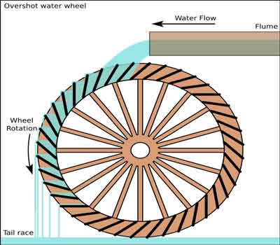
Overshot waterwheel A vertically-mounted wheel that is rotated by falling water striking paddles, blades or buckets near the top of the wheel is said to be overshot. In true overshot wheels the waters passes over the top of the wheel, but the term is sometimes applied to backshot or pitchback wheels where the water goes down behind the waterwheel.
Typical overshot wheels has the water channeled to the wheels at the top and slightly to one side in the direction of rotation. The waters collects in the buckets on that side of the wheel, making it heavier than the other "empty" side. The weight turns the wheels, and the waters flows out into the tail-water when the wheels rotates enough to invert the buckets. The overshot design can use all of the waters flow for power (unless there is a leak) and does not require rapid flow.
Unlike undershot wheels, overshot wheels gain a double advantage from gravity. Not only is the force of the flowing water partially transferred to the wheel, the weight of the waters descending in the wheel"s buckets also imparts additional energy. The mechanical power derived from overshot wheels is determined by the wheel"s physical size and the available head, so they are ideally suited to hilly or mountainous country.
Overshot wheels demand exact engineering and significant head, which usually means significant investment in constructing a dam, millpond and waterways. Sometimes the final approach of the wat ers to the wheel is along a lengthy flume or penstock.http://en.wikipedia.org/wiki/Wikipedia:Text_of_the_GNU_Free_Documentation_License
Sullivan"s waterwheels , A small family business, located in the South Carolina Foothills! We want everyone to be able to own a beautiful relaxing millwheel of their own! Whether it be for your garden,pond,or as a beautiful addition to any landscaping, home and garden & yard large are small. We strive to bring you the best.

There are many wheel configurations, vane/blade shapes and water-flow patterns. Undershot wheels and horizontal wheels were the most common choices for tide mills. Since the height of the impoundment area was the height of high tide, the head of water was probably not high enough to power an overshot wheel.
Probably the most important of the early engines which utilized water power was the vertical waterwheel. Its two basic forms are the undershot and the overshot. The undershot vertical wheel rotated in the vertical plane and had a horizontal axis. It normally had flat radial blades attached to its periphery and derived its motion from the impact of water flowing under the wheel and against these blades. While capable of working on any convenient stream without mill races (narrow artificial water channels, it worked most effectively in a race and with a stable volume of water running at a fairly high velocity. [Stronger than a Hundred Men: A History of the Vertical Water Wheel by Terry S. Reynolds Baltimore: The Johns Hopkins University Press, 1983.]
The Undershot Wheel worked in a running stream and could turn in shallow water. It was often built by the first settlers since it was relatively simple to set up … They were common in the early days when a dam could be built to compensate for dry periods … . [Mill: The History and Future of Naturally Powered Buildings by David Larkin. New York, 2000.]
The tub wheel could only work where the water flowed regularly throughout the year, and needed at least an eight-foot fall. The tub wheel was horizontal and was described as acted upon by percussion of water. The shaft is vertical, running the stone of top of it, and serves as a spindle. The water is shot on the upper side of the wheel in the direction of a tangent fitted with blades. It revolves in a sturdy tub, projecting far enough above the wheel to prevent the water from shooting over it, and whirls above it until it strikes the buckets. . [Mill: The History and Future of Naturally Powered Buildings by David Larkin. New York, 2000.]
The overshot vertical wheel was a much more efficient device. Water was fed at the top of the overshot wheel into “buckets” or containers built into the wheel’s circumference, and the weight of the impounded water, rather than its impact, turned the wheel. Each “bucket” discharged its water into the tail race at the lower portion of its revolution and ascended empty to repeat the process. The overshot wheel was usually more expensive than the undershot, since a dam and an elevated head race were normally required to build up a large fall of water and to lead the water to the wheel’s summit. It was suitable mainly to low water volumes and moderately high falls.
It is likely that the [emergence of undershot and overshot wheels] was at least partially influenced by several more primitive devices which tap the power of falling water – the water lever, the noria, and the primitive horizontal watermill. [Stronger than a Hundred Men: A History of the Vertical Water Wheel by Terry S. Reynolds Baltimore: The Johns Hopkins University Press, 1983.]
The overshot wheel required a dam above it so that the weight of water falling on it would make it turn. After one-third of a revolution, the water was spilled from the wheel. The water first striking the wheel gave it momentum, but the weight of the water in its buckets kept it turning. [Mill: The History and Future of Naturally Powered Buildings by David Larkin. New York, 2000.]
The difference between the pitch-back and the overshot wheels is that the trough stops shorter here and pours the water onto the wheel before the top of the wheel, or ‘on the near side’ as the millwrights used to say. The result therefore is that the wheel revolves in the opposite direction from the overshot, i.e. towards the flume or head-race. The buckets face in the opposite direction and the water therefore falls off at the same side as that on which it was received. [British Water-Mills by Leslie Syson. London, 1965]
The breast wheel, like the undershot wheel, turned in the opposite direction to the overshot wheel and received water above its center shaft at the nearest point of the water supply, and revolved easily because it was less loaded with water. . [Mill: The History and Future of Naturally Powered Buildings by David Larkin. New York, 2000.]
The flutter wheel was used when there was a large supply of water. It was small, low and wide—about three feet in diameter and up to eight feet wide. It got its attractive name from the sound it made. As the wheel went around, the blades cut through the entering water, making a noise like the fluttering wings of a bird. It was used almost entirely to power early sawmills. . [Mill: The History and Future of Naturally Powered Buildings by David Larkin. New York, 2000.]
The turbine with its curved blades, eventually replaced the waterwheel [in the mid-nineteenth century]. … Roy S. Hubbs pointed out that older undershot waterwheels presented a flat blade for the incoming water to impact, allowing half of the velocity to pass through unchecked. The Poncelet design [and the later resulting turbine] presented a curved blade with its lip angled tangentially to the incoming water … Benoit Fourneyron turned the wheel on its side and dropped the water into its center, allowing the water to flow simultaneously out of all the passages between the blades. … Since the turbine used all the openings between its blades simultaneously, it could be made much smaller. It turned much faster than the larger wheels. . [Mill: The History and Future of Naturally Powered Buildings by David Larkin. New York, 2000.]
Operating on the seesaw principle, the water lever utilized the power of falling water, but without the continuous rotary motion of water wheels. One end of a pivoted beam was equipped with a spoon-shaped bucket. On the other end was a hammerlike counterweight used for pounding or crushing. Water was directed into the bucket from a falling stream; the bucket filled, overweighed the hammer, and lifted it. The ascent of the bucket caused the water to spill; the hammer than overbalanced the bucket and fell. The cycle was then repeated to produce a steady pounding action.
The noria used for raising water, was form of undershot water wheel, but it activated no machinery (such as gears or millstones) beyond itself. It was simply a large vertically situated wheel, sometimes as much at 50-80 feet in diameter, equipped with radial blades which rotated the apparatus as they were impacted by the flowing water in which the lower portion of the wheel was immersed. Buckets of wood, bamboo, or pottery were attached to the rim of the wheel. As the device rotated, they were filed with water at the bottom of the wheel; the water was carried upwards in the buckets and emptied near the top of the wheel into a trough. The buckets were the returned empty to the bottom of the wheel to repeat the process.
Based on the surviving evidence, it would appear that the vertical undershot watermill, the horizontal watermill, and the noria appeared almost simultaneously in the Mediterranean world in the first century B.C. and that at approximately the same time some form of water-powered prime mover was developed in China.
By the close of the Middle Ages watermills were in use on streams of every type. They dammed up the rivers of medieval man; they were on the banks of his brooks and creeks, in the middle of his rivers, under his bridges, and along his coastlines. They impeded navigation and created streams (in the form of mill races and power canals) and lakes (in the form of storage reservoirs behind waterpower dams) where none had existed before.
Through all of antiquity and on into the early Middle Ages almost the only work to which the force of falling water was applied was grinding wheat. This was always to be one of its more important functions. But by the tenth century, European technicians had begun to adapt the vertical water wheel to other tasks. By the sixteenth century, in addition to flour mills, there were hydropowered mills for smelting, forging, sharpening , rolling slitting, polishing, grinding, , and shaping metals. Water wheels were available for hoisting materials and for crushing ores. There were mills for making beer, olive oil, poppy oil, mustard, coins, and wire. Water wheels were used in the preparation of pigment, paper, hemp, and tanning bark, and for fulling, sawing wood, boring pipes, and ventilating mines.
[In North America] the resort to water power usually came quickly after settlement [in colonial America]. The first permanent English settlement in North America was at Jamestown, Virginia, in 1607. Early in that settlement’s history the Virginia Company instructed its governor to build watermills on every plantation. By 1694 Virginia had five watermills. Maryland had a watermill in 1634, the very year it was first settled, and Swedish authorities responsible for settlements on the Delaware in the1640s made the erection of watermills one of their first concerns. The colony of Massachusetts, first settled in 1620, had a watermill at Dorchester by 1633, and mills at Roxbury, Lynn, and Watertown by 1635. These were all flour mills. But according to one authority, the Piscataqua River above Portsmouth, N.H., was dammed for a sawmill as early as 1623. In 1646, on the Saugus River, Massachusetts built an iron mill, complete with water-activated trip-hammers, blast furnace, bellows, rollers, and slitters. By 1700 there were few New England villages without a watermill.
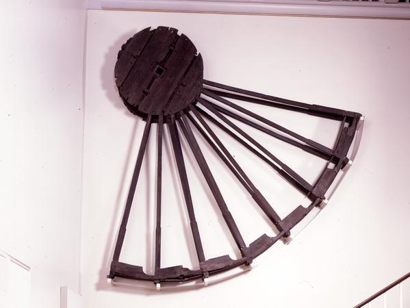
Frequently used in mines and probably elsewhere (such as agricultural drainage), the reverse overshot water wheel was a Roman innovation to help remove water from the lowest levels of underground workings. It is described by Vitruvius in his work
The Roman author Vitruvius gives explicit instructions on the construction of dewatering devices, and describes three variants of the "tympanum" in Chapter X of
Pliny the Elder is probably referring to such devices in a discussion of silver/lead mines in his silver in his time, many of the silver mines having been started by Hannibal. One of the largest had galleries running for between one and two miles into the mountain, "water-men" (in Latin "aquatini") draining the mine, and they
That they stood suggests that they operated the wheels by standing on the top to turn the cleats, and continuous working would produce a steady stream of water.
Fragments of such machines have been found in mines which were re-opened in the Victorian era in Spain, especially at Rio Tinto, where one example used no less than 16 such wheels working in pairs, each pair of wheels lifting water about 3.5 metres (11 ft), so giving a total lift of 30 metres (98 ft). The system was carefully engineered, and was worked by individuals treading slats at the side of each wheel. It is not an isolated example, because Oliver Davies mentions examples from the Tharsis copper mine and Logroño in Spain, as well as from Dacia. The gold deposits in Dacia, now modern Romania were especially rich, and worked intensively after the successful Roman invasion under Trajan. According to Oliver Davies, one such sequence discovered at Ruda in Hunedoara County in modern Romania was 75 metres (246 ft) deep. If worked like the Rio Tinto example, it would have needed at least 32 wheels.
One such wheel from Spain was rescued and part of it is now on display in the British Museum. Some of the components are numbered, suggesting that it was prefabricated above ground before assembly in the underground passages. In the 1930s, a fragment of a wooden bucket from a drainage wheel was found in deep workings at the Dolaucothi gold mine in west Wales, and is now preserved in the National Museum of Wales in Cardiff. It has been carbon dated to about 90 AD. From the depth of 50 metres (160 ft) below known open workings, it can be inferred that the drainage wheel was part of a sequence just like that found in Spain. The shape of the edge of one of the lifting buckets is almost identical with that from Spain, suggesting that a template was used to make the devices.
They were also used in series, so increasing the lift of water from the workings. However, they must have been more difficult to operate since the user had to stand on a slanting surface to turn the screw. The steeper the incline, the greater the risk of the user slipping from the top of the screw. No doubt the reverse water wheel was easier to use with a horizontal treading surface. On the other hand, the screw could be operated by a crank handle fitted to the central axle, but would be more tiring since the weight of the operator does not bear on the crank, as it does when trod from above.
Like the reverse water wheel, the cochlea was used for many other purposes apart from draining mines. Irrigation of farmland would have been the most popular application, but any activity which involved lifting water would have employed the devices.
Multiple sequences of water wheels were used elsewhere in the Roman Empire, such as the famous example at Barbegal in southern France. This system was also a stack of 16 wheels but worked like a normal overshot wheel, the wheels driving stone mills and used to grind grains. The water mills were worked from a masonry aqueduct supplying the Roman town at Arles, and the remains of the masonry mills are still visible on the ground today, unlike the underground drainage systems of the mines, which were destroyed by later mining operations. Other such sequences of mills existed on the Janiculum in Rome, but have been covered and changed by later buildings built on top of them.
To do this you will need to know two things, the quantity of water and the height of the water fall. From this you can determine the Horsepower at the axle of the waterwheel.
To get electricity out of a waterwheel you will have to gear the RPMs of the waterwheel (generally from 5-10 rpm”s up t0 500 - 1700 rpm’s) and then run it through a generator or a DC motor to charge a battery bank. This will generally cut your power at the axle HP by almost 1/3 to 1/2. A waterwheel is really designed to do mechanical work.
Water wheel design has evolved over time with some water wheels oriented vertically, some horizontally and some with elaborate pulleys and gears attached, but they are all designed to do the same function and that is too, “convert the linear motion of the moving water into a rotary motion which can be used to drive any piece of machinery connected to it via a rotating shaft”.
Early Waterwheel Design were quite primitive and simple machines consisting of a vertical wooden wheel with wooden blades or buckets fixed equally around their circumference all supported on a horizontal shaft with the force of the water flowing underneath it pushing the wheel in a tangential direction against the blades.
These vertical waterwheels were vastly superior to the earlier horizontal waterwheel design by the ancient Greeks and Egyptians, because they could operate more efficiently translating the hydrokinetic energy of the moving water into mechanical power. Pulleys and gearing was then attached to the waterwheel which allowed a change in direction of a rotating shaft from horizontal to vertical in order to operate millstones, saw wood, crush ore, stamping and cutting etc.
Most Waterwheels also known as Watermills or simply Water Wheels, are vertically mounted wheels rotating about a horizontal axle, and these types of waterwheels are classified by the way in which the water is applied to the wheel, relative to the wheel’s axle. As you may expect, waterwheels are relatively large machines which rotate at low angular speeds, and have a low efficiency, due to losses by friction and the incomplete filling of the buckets, etc.
The action of the water pushing against the wheels buckets or paddles develops torque on the axle but by directing the water at these paddles and buckets from different positions on the wheel the speed of rotation and its efficiency can be improved. The two most common types of waterwheel design is the “undershot waterwheel” and the “overshot waterwheel”.
The Undershot Water Wheel Design, also known as a “stream wheel” was the most commonly used type of waterwheel designed by the ancient Greeks and Romans as it is the simplest, cheapest and easiest type of wheel to construct.
In this type of waterwheel design, the wheel is simply placed directly into a fast flowing river and supported from above. The motion of the water below creates a pushing action against the submerged paddles on the lower part of the wheel allowing it to rotate in one direction only relative to the direction of the flow of the water.
This type of waterwheel design is generally used in flat areas with no natural slope of the land or where the flow of water is sufficiently fast moving. Compared with the other waterwheel designs, this type of design is very inefficient, with as little as 20% of the waters potential energy being used to actually rotate the wheel. Also the waters energy is used only once to rotate the wheel, after which it flows away with the rest of the water.
Another disadvantage of the undershot water wheel is that it requires large quantities of water moving at speed. Therefore, undershot waterwheels are usually situated on the banks of rivers as smaller streams or brooks do not have enough potential energy in the moving water.
One way of improving the efficiency slightly of an undershot waterwheel is to divert a percentage off the water in the river along a narrow channel or duct so that 100% of the diverted water is used to rotate the wheel. In order to achieve this the undershot wheel has to be narrow and fit very accurately within the channel to prevent the water from escaping around the sides or by increasing either the number or size of the paddles.
The Overshot Water Wheel Design is the most common type of waterwheel design. The overshot waterwheel is more complicated in its construction and design than the previous undershot waterwheel as it uses buckets or small compartments to both catch and hold the water.
These buckets fill with water flowing onto the wheel through a penstock design above. The gravitational weight of the water in the full buckets causes the wheel to rotate around its central axis as the empty buckets on the other side of the wheel become lighter.
This type of water wheel uses gravity to improve output as well as the water itself, thus overshot waterwheels are much more efficient than undershot designs as almost all of the water and its weight is being used to produce output power. However as before, the waters energy is used only once to rotate the wheel, after which it flows away with the rest of the water.
Overshot waterwheels are suspended above a river or stream and are generally built on the sides of hills providing a water supply from above with a low head (the vertical distance between the water at the top and the river or stream below) of between 5-to-20 metres. A small dam or weir can be constructed and used to both channel and increase the speed of the water to the top of the wheel giving it more energy but it is the volume of water rather than its speed which helps rotate the wheel.
Generally, overshot waterwheels are built as large as possible to give the greatest possible head distance for the gravitational weight of the water to rotate the wheel. However, large diameter waterwheels are more complicated and expensive to construct due to the weight of the wheel and water.
When the individual buckets are filled with water, the gravitational weight of the water causes the wheel to rotate in the direction of the flow of water. As the angle of rotation gets nearer to the bottom of the wheel, the water inside the bucket empties out into the river or stream below, but the weight of the buckets rotating behind it causes the wheel to continue with its rotational speed.
Once the bucket is empty of water it continues around the rotating wheel until it gets back up to the top again ready to be filled with more water and the cycle repeats. One of the disadvantages of an overshot waterwheel design is that the water is only used once as it flows over the wheel.
The Pitchback Water Wheel Design is a variation on the previous overshot waterwheel as it also uses the gravitational weight of the water to help rotate the wheel, but it also uses the flow of the waste water below it to give an extra push. This type of waterwheel design uses a low head infeed system which provides the water near to the top of the wheel from a pentrough above.
Unlike the overshot waterwheel which channelled the water directly over the wheel causing it to rotate in the direction of the flow of the water, the pitchback waterwheel feeds the water vertically downwards through a funnel and into the bucket below causing the wheel to rotate in the opposite direction to the flow of the water above.
Just like the previous overshot waterwheel, the gravitational weight of the water in the buckets causes the wheel to rotate but in an anti-clockwise direction. As the angle of rotation nears the bottom of the wheel, the water trapped inside the buckets empties out below. As the empty bucket is attached to the wheel, it continues rotating with the wheel as before until it gets back up to the top again ready to be filled with more water and the cycle repeats.
The difference this time is that the waste water emptied out of the rotating bucket flows away in the direction of the rotating wheel (as it has nowhere else to go), similar to the undershot waterwheel principal. Thus the main advantage of the pitchback waterwheel is that it uses the energy of the water twice, once from above and once from below to rotate the wheel around its central axis.
The result is that the efficiency of the waterwheel design is greatly increased to over 80% of the waters energy as it is driven by both the gravitaional weight of the incoming water and by the force or pressure of water directed into the buckets from above, as well as the flow of the waste water below pushing against the buckets. The disadvantage though of an pitchback waterwheel is that it needs a slightly more complex water supply arrangement directly above the wheel with chutes and pentroughs.
The Breastshot Water Wheel Design is another vertically-mounted waterwheel design where the water enters the buckets about half way up at axle height, or just above it, and then flows out at the bottom in the direction of the wheels rotation. Generally, the breastshot waterwheel is used in situations were the head of water is insufficient to power an overshot or pitchback waterwheel design from above.
The disadvantage here is that the gravitational weight of the water is only used for about one quarter of the rotation unlike previously which was for half the rotation. To overcome this low head height, the waterwheels buckets are made wider to extract the required amount of potential energy from the water.
Breastshot waterwheels use about the same gravitational weight of the water to rotate the wheel but as the head height of the water is around half that of a typical overshot waterwheel, the buckets are a lot wider than previous waterwheel designs to increase the volume of the water caught in the buckets.
The disadvantage of this type of design is an increase in the width and weight of the water being carried by each bucket. As with the pitchback design, the breastshot wheel uses the energy of the water twice as the waterwheel is designed to sit in the water allowing the waste water to help in the rotation of the wheel as it flows away down stream.
Historically water wheels have been used for milling flour, cereals and other such mechanical tasks. But water wheels can also be used for the generation of electricity, called a Hydro Power system.
By connecting an electrical generator to the waterwheels rotating shaft, either directly or indirectly using drive belts and pulleys, waterwheels can be used to generate power continuously 24 hours a day unlike solar energy. If the waterwheel is designed correctly, a small or “micro” hydroelectric system can produce enough electricity to power lighting and/or electrical appliances in an average home.
Look for Water wheel Generators designed to produce its optimum output at relatively low speeds. For small projects, a small DC motor can be used as a low-speed generator or an automotive alternator but these are designed to work at much higher speeds so some form of gearing may be required. A wind turbine generator makes an ideal waterwheel generator as it is designed for low speed, high output operation.
If there is a fairly fast flowing river or stream near to your home or garden which you can use, then a small scale hydro power system may be a better alternative to other forms of renewable energy sources such as “Wind Energy” or “Solar Energy” as it has a lot less visual impact. Also just like wind and solar energy, with a grid-connected small scale waterwheel designed generating system connected to the local utility grid, any electricity you generate but don’t use can be sold back to the electricity company.
In the next tutorial about Hydro Energy, we will look at the different types of turbines available which we could attach to our waterwheel design for hydro power generation. For more information about Waterwheel Design and how to generate your own electricity using the power of water, or obtain more hydro energy information about the various waterwheel designs available, or to explore the advantages and disadvantages of hydro energy, then Click Here to order your copy from Amazon today about the principles and construction of waterwheels which can be used for generating electricity.

The path that the water takes through a turbine and the general layout is often used for classification, like tangential-flow, radial-flow cross-flow and axial-flow. Below are the various categories of ‘water driven prime mover that can be used to convert the ‘potential energy’ in a river or stream into usable ‘mechanical’ or ‘electrical’ energy. This section continues with information on what types of turbine are suitable in various sites and applications.
Gravity devices are those where any kinetic energy present at the entry of the device is either minimal or lost in turbulence and does nor contribute measurably to the output of the device. Such devices include most waterwheel types, Archimedes screws (where the outer case rotates with the flutes); Hydrodynamic screws (as used for sewage pumping and now being used in reverse as low-head prime-movers); Norias (more commonly used for raising water) and consist of a string of buckets like an overshot waterwheel attached to form a chain, and positive displacement devices or hydraulic engines.
Impulse turbines are those where the potential energy in a ‘head of water’ is largely converted into kinetic energy at a nozzle or spout. The simplest of such devices is the Gharat or Norse Wheel (where the conversion to kinetic energy takes place in an open flume). The more conventional devices harness the potential energy in a pipeline or penstock that terminates in a nozzle. The flow path through the turbine is usually used to describe the specific device, namely, tangential-flow, radial-flow, cross-flow, axial-flow or mixed-flow. Specific turbine designers have been associated with most of these devices, though confusion can result because they often designed several different types of device (The Pelton Waterwheel Company also made cased reaction turbines, Herschel pre dates Jonval’s patent that was the precursor of the Turgo Impulse wheel, a single nozzle version developed by Gilkes. Donat Banki, a Hungarian was also making cross-flow turbines many years before Mitchell and Ossburger came on the scene.
Reaction turbines are those where the turbine runner is usually completely flooded and the transfer of energy from the water to the turbine runner is achieved by a combination of reaction and/or lift. Some designs of cross-flow turbine in common use a combination of impulse and reaction. Reaction turbines have had a more complex development, with many designers and factories adding features such as movable ‘wicket gates’ that resulted in Francis’s name becoming the tag by which this group of turbines are now known. The Kaplan turbine developed in the 1930s is a sophisticated variable geometry version of the ‘propeller turbine’ that as its name suggests is similar to a ship’s propeller in a housing. Halfway between these types is the single regulated propeller turbine, where either the runner blades or the ‘guide vanes’ (wicket gates) are adjustable.
Free-stream devices encompass large slow running wheels and turbines, some of which are being tried out for marine energy applications. Like wind turbines, the power delivered increases as a cube of the velocity, such that a doubling of the velocity gives an eight fold increase in power output. The devices themselves are very large and slow running and only have very specialised applications for extracting small amounts of power from bank-side locations on very large rivers.
High head sites with over 20 metres of fall, where the water is conveyed directly to the turbine in a pipe (penstock) or via an open canal followed by a piped section, generally use impulse turbines. The reason is that high head sites are usually subject to significant changes in water flow and reaction turbines like the Francis are not able to cope with such variations. Silt in the water can also cause a lot of damage to Francis turbines that is expensive to repair.
One of the most successful high head turbines was developed in California during the gold rush from a device referred to as a ‘hurdy gurdy’ that was basically a cartwheel with buckets around the periphery. A carpenter by the name of Lester Pelton came up with the now familiar double bucket shape and went on to found ‘The Pelton Watewheel Company’ of San Francisco. The bucket design was later improved by Doble who joined the company as an engineer in 1899. Doble’s improvement is the central cut-out in the bucket that prevents the water jet from first striking the back of the bucket and wasting energy. www.oldpelton.net. Today, similar machines are operating from over 1000 metres of fall and generating up to 100MW of power.
A simple weir is all that is required to divert the stream into the penstock (pipeline) via a de-silting chamber to remove any sand. Water storage may be included if the terrain allows and if it is advantageous to generate more power for short periods or where it is necessary to store water for generation when flows are very low. A low-pressure pipe or open canal may also be used to reduce to overall cost if it allows a short steep decent to the powerhouse using less high-pressure pipe.
Pelton turbines are efficient over a very wide range of flows but at lower heads the speed is too low for belt drives, so we reduce the pitch circle and modify the bucket shape to increase the specific speed. The jets may have plain nozzles or adjustable spear valves to adjust the water consumption to the available stream flow. It is usual with larger machines to have ‘deflectors’ that divert the water away from the runner for controlling the speed without altering the water flow. They can also be used for emergency shutdown.
For thousands of years waterpower has been harnessed for milling and pumping water. In the Developing World many are still in daily use, but in Western Countries they have usually fallen into disrepair as a result of competition from diesel and electric power. In the U.K. there were over 70,000 working mills at the end of the 18th century and now there are a few hundred. These mills fall into a number of categories that will determine their suitability for redevelopment.
The waterwheels that were used on these sites in the U.K. are usually of the Roman or horizontal shaft type, though the vertical shaft type is much more common in Mediterranean and Asian countries. Depending on the fall of water available, the horizontal wheels are classified into ‘Overshot’, ‘Breast-shot’, ‘Back-shot’ and ‘Under-shot’. With the exception of projects to restore a mill to its original design, or where the visual appearance is important to maintain, only the overshot wheel is suitable for a new power generation projects.
Overshot waterwheels are the most fish-friendly and able to handle leaves and sticks. A similar device is the Noria or chain wheel, which has the disadvantage of potential more maintenance, but it runs faster, is more efficient and easier to install than an overshot waterwheel.
The power available is a function of the head and flow so building a large wheel will only increase the cost and reduce the shaft speed but not increase the power. Major components in the cost are the primary gearbox and the material required in the construction of the wheel itself. We are happy to build any type of waterwheel, but the cost is likely to be significantly greater than that of an equivalent turbine, when you take the gearing and installation costs into consideration. There are no short cuts with waterwheels and the engineering has to be good, on account of the high torque in the low speed drive.
Mills with ponds are seldom suitable for redevelopment for anything other than a few kilowatts because the water flow is obviously too little to sustain the mill on a continuous basis, and it is much too expensive to install a wheel or turbine that can only be operated for a few hours a day. In some cases the ponds were only used in the summer months when the water was low, but today we are looking to the higher winter flow for the bulk of the power that can be used for heating. There is always a loss of head into and out of the pond, but this may be recoverable with a turbine installation.
Mills with leats, lades or channels take their water from a water course along the side of a valley at a gradient that is usually less than one in five hundred. At a suitable point when enough fall can be achieved in one place, the mill is built. The only limitations to future development are the actual head and flow available. Since there was a mill there anyway there should be enough power for domestic purposes. Improvements to the leat and head are usually possible but are very site specific. Modern mini excavators make leat widening and maintenance much easier than when the mills were first built.
Mills on weirs or with short wide diversion channels present the most difficult challenge for the developer. The available head may only be a metre or so and the flow required to generate useful amounts of power will be several cubic metres of water per second. The undershot waterwheels that were originally used at these sites are totally redundant on account of their high cost and low efficiency. The exact layout of the site becomes increasingly important with the lower falls, because access for excavators and to install the large items of equipment is more difficult.
Open flume installations are the most usual for the very low head sites, and employ fixed geometry propeller turbines on account of their simple construction and high ‘specific speed’. The more complex variable ‘Kaplan’ type turbines are not economic for these small schemes and it is easier to achieve ‘flow control’ by installing more than one machine or by running until the water has fallen by say 100mm and then switching off automatically until it has come up again. This latter system can be used for heating
Tubular turbines of the propeller type can be used for mill sites with a higher head, typically those that originally employed ‘Overshot’ waterwheels. Many different arrangements are possible to suite existing civil works but the main compromise arises from their inflexible performance. If the mill is only extracting a small percentage of the available water from the main river, then there is no problem. If however the water flow reduces below that which is required to supply the turbine, either water storage, another smaller turbine or a change in turbine speed will be required.
Archimedes Screws have come into the news in recent years because of their reported fish friendliness, but firstly the units being described are NOT Archimedes screws but Screw pumps running in reverse (hydrodynamic screws) and secondly the hydrodynamic screws are not as friendly as they might first appear. The difference in respect to fish friendliness is potentially significant since the true Archimedes screw has its outer casing rotating with the screw flights so that no fish, eel or lampray can be killed or injured by getting caught in the gap or abraded against the concave that will undoubtedly become rough with time and damage.
Low cost open impulse turbineshave been developed by us, primarily for projects in the Developing World. Installed outside the mill house like a waterwheel, it is an economic alternative for smaller domestic sites here in the U.K. They cannot be used with a draft tube since the runner is open to the atmosphere but the installation and maintenance is much simpler. The valve control shaft is extended through the mill house wall to an operating lever on the ,inside or a simple open shoot conveys the water directly to the runner in the manner of the old ‘flutter wheels’ used in the USA in the 19c. Installation work is usually kept to a minimum and may be in an old waterwheel pit or even behind an existing wheel under the launder. A vertical shaft version like the Indian Gharat can produce considerably more power by increasing the entry area, whilst maintaining its self-cleaning characteristics.
Portable turbines are highly adaptable and be assembled on site in a few hours. Applications include ‘Rural Development’, camping and field hospitals. Typical outputs range from 200 watts to 50 kW. The inlet works are prefabricated and the pipeline is either flexible polyethylene or ‘lay-flat’ coiled pipe. The whole unit can be built into a trailer or air-portable unit for rapid deployment in the field. The buckets that are divided along their centre line by a splitter ridge, turn the jet of water that is directed at them, through 1800 so that the energy is transferred efficiently to the shaft.
Turbines that are suitable for a particular type of site and turbines that are suitable for particular type of application are referred to as ‘groups’. Hence you can have a group of ‘Hillstream’ turbines for upland sites, or a group of ‘Agricultural’ turbines for agricultural applications. The site may be defined topographically as an upland or ‘Hillstream’ site, or as a lowland or ‘Millstream’ site. Each of these groups I then divided into two sub-groups depending on the actual site layout and general features. The ‘Hillstream’ group is comprised of vertical and horizontal shaft impulse turbines that may be either direct drive, belt drive or overhung from the generator. The application for the plant may be to generate electricity, mechanically power machinery or pump water for irrigation or for a drinking water supply. The application will also have a bearing on the materials, the sophistication, the governing system and the general build.

Back in 1947, Popular Science printed a five-part article by C.D. Bassett that very concisely sketched out every step necessary for the establishment of a small water-power plant on a farm or homestead. That information is still just as valuable today for many of MOTHER’s readers as it was 30 years ago . . . and that’s why THE MOTHER EARTH NEWS asked for — and received — permission to reprint the whole series as a two-part article in MOTHER NOs. 13 and 14. The Popular Science material was also included — by permission — in THE MOTHER EARTH NEWS Handbook of Homemade Power.
If any of the terms or ideas in the accompanying article are unfamiliar to you, then, you have three choices: [1] You can trot on down to your local library and exhume the old, original C.D. Bassett articles from the 1947 issues of Popular Science, [2] you can order out MOTHER NOS. 13 and 14 at $2.00 apiece from the ad on pages 114-115 of this issue, or[3] you can get your own copy – $1.95 plus 75¢ shipping and handling — of The Handbook of Homemade Power by using the MOTHER’s Bookshelf ad on pages 174 -177 of this issue. Any way you go about it, you’re going to learn all you need to know to lay out, install, and operate your own water-power system. All you’ll need to add to this information is a free-flowing stream . . . and you’re in business.
One final note: The following article describes a homemade overshot water wheel set up to do only one thing . . . pump water from a spring to a set of farm buildings 100 feet above. If you’re more interested in learning how to use the same kind of wheel to generate electricity, see the article, schematic drawing, and photographs of Thomas Oates’ water-wheel powered DC electrical system in MOTHER NO. 24. That piece was also reprinted in The Handbook of Homemade Power. — The Editors.
One very successful example of this “back to basics” trend is the water wheel-powered water pump now in operation on the Robert Wooding farm near Halifax, Virginia. The pump-powered by a home designed and home-built 6 1/2-foot, steel water wheel which, in turn, is spun by water from a stream on the family farm shoves 1,440 gallons of pure spring water 100 feet uphill every 24 hours. And, since the system was set up, it hasn’t cost the Woodings anything for its tireless round-the-clock operation . . . except a few cents for lubrication.
“There are three things I especially like about my wheel,” says Bob blooding. “One, unlike the hydraulic ram pumps featured several times in MOTHER, it doesn’t use gallons and gallons of our drinking water just to pump a few gallons up the hill. Two, the overshot design of our wheel makes very efficient use of the small stream we tap for power. And, three, there’s not a whole lot of banjo work to a rig like this once you’ve got it going. We spent a little time and money setting our system up, to be sure, but it’s been practically maintenance-free ever since. About all we do is give its bearings a shot of grease two or three times a year.”
The Woodings were fortunate enough to have a picturesque stream on their property (the first and most obvious requirement for any water-power system!) . . . but that’s as far as their luck went. At no single spot along the creek was there enough “fall” to turn the 6 1/2-foot overshot wheel that Bob figured on installing.
Fall, as the name implies, is the amount of vertical distance that running water drops as it moves down a stream (if there were no fall at all, the water — obviously — wouldn’t run and the stream wouldn’t be a stream . . . it would be a slough or a lake).
The ideal location, of course, for an overshot water wheel (which must be positioned in a stream at a spot where the water abruptly drops at least as far as the wheel is tall) is a natural rapids or waterfall. If, like the Woodings, you find yourself working with a stream that has no such abrupt natural drop, however, you’ll have to do what the Woodings did: Build your own man-made waterfall . . . which, as we all know, is commonly called a dam.
(NOTE: The reprinted series of five articles from Popular Science mentioned at the beginning of this piece contains everything you need to know to calculate the flow and call of a stream, design several kinds of dams, build and install an overshot wheel, and otherwise fabricate and operate a farm- or homestead-sized water-power system. — The Editors.)
“We needed about a seven-foot fall for our 6 1/2-foot-tall wheel,” Bob blooding remembers, “so we built a three-foot-tall dam . . . and then flumed the water from the top of that dam to a spot 120 feet further downstream where the creek’s banks were an additional tour feet lower. The dam’s height of three feet plus the additional four feet of drop we picked up by running our flume that tar added up to the seven feet of fall, or head, that we needed for our wheel.”
The Woodings’ flume is a combination of approximately 85 feet of four-inch aluminum pipe feeding into an additional 46 1/2 feet of wooden trough measuring six inches deep by six inches wide. (The aluminum pipe, which extends about a foot and a half into the trough, can be lifted out and set into a curved metal deflector which routes its water back into the stream whenever the Woodings want to stop the wheel.)
Traditional flumes for homestead water wheels, of course, were of all-wood construction. But Bob Wooding decided to use rot-free, corrosion-free aluminum pipe for the first two-thirds of his wheel’s feeder line, where the flume had to extend into the water and then run underground. The pipe’s inlet is covered with a screen to keep the line from becoming clogged with misguided leaves, turtles, and crawfish. Care was also taken to position the opposite (wooden) end of the flume so that its discharge of water would hit the exact top-center of the overshot wheel.
Although the blooding family’s water system for their house, stables, and swimming pool is powered by the stream on their farm . . . the actual water which flows through that system comes from a clear, cool, pure spring. This spring, too (just like their dam), is located about 120 feet from the overshot wheel and pump that is the heart of the whole hookup. So, in addition to the flume which carries the “driving” water from the dam to the wheel, another one-inch pipe was laid to carry the “driven” water from the spring to the pump that is installed next to (and driven by) the wheel.
Luckily for the Woodings, the spring water’s temperature stays 52 degrees Fahrenheit year round. Merely by laying this feeder pipe so that it has a continuous slight grade from the spring down to the pump a few feet below, then, the family has been able to keep their water supply from freezing in the winter without going to the trouble of burying the pipe below the frost line.
When you buy a manufactured water wheel, a large portion of the purchase price goes to pay for the equipment’s design. It follows, then, that you can save yourself a sizable chunk of cash by working up the specifications for your own wheel . . . and that’s exactly what Bob Wooding did.
Actually, this isn’t as difficult as you might think. To extract maximum power from any given flow of water with an overshot wheel is largely a matter of calculating the proper depth and angle of the buckets placed around the wheel’s rim (ideally, each bucket must be completely filled at top center and then carry its load of water without spilling a drop until just the instant it passed bottom center . . . but anything even remotely approaching this ideal will handle the job satisfactorily in most homestead applications).
(EDITORS’ NOTE: If you scale up the drawings shown here and use them to construct a wheel ranging anywhere from two feet up to 20 feet in diameter — and if you work carefully and in a craftsman-like manner — the chances are good that your finished wheel will work well enough to make you pretty dang proud of yourself. If you really want to go for the finer points of maximum efficiency, however, you can work from the more detailed dimensions and angles given in the full-page drawing of an overshot wheel on page 31 of MOTHER N0. 14.)
After drawing up his design (complete with “dribble” hole in the bottom of each bucket, so that the wheel is self-draining when not in use!), Bob had the individual parts for his water wheel prefabbed by the Carolina Steel Company in Greensboro, North Carolina. A Richmond, Virginia representative for the firm says that the 3/16 inch steel plate used in the 980-pound assembly’s 37 eight-by-twelve-inch buckets, its five-inch-wide rim, and its one-foot-wide sole plate would currently cost about $130. You can add on another $70 for burning, forming, and welding the metal. (These prices, of course, will vary in different parts of the country and — as time goes on — are sure to escalate right along with the price of everything else.)
The hubs for the Wooding wheel were pretty much “Chinese copied” from the hubs manufactured years ago by the now-defunct Fitz Water Wheel Company of Hanover, Pennsylvania. Bob had them cast at a local foundry from a wooden pattern that he made himself, and the materials and labor for the raw castings set him back only $25. A nearby machine shop then bored out the hubs on a lathe, cut keyways into the bores, and made up the pair (each half of the set contains six 3/8 inch by 2 inch spokes) of spokes for the wheel . . . all for only $60 complete.
Once he had all the components for his wheel prefabbed and in hand, there was nothing for Bob Wooding to do but assemble the power unit. “I used calipers to measure and remeasure the spaces around the rim for my buckets until I had them exact to the width of a pencil mark,” Bob says. “Then I tacked the buckets in place all the way around and rechecked everything before I finally welded them in permanently. If you try to finish-weld each one as you go without tacking everything together first, you know, you can get off kilter and warp the whole wheel.”
Every one of the six “ears”, or extensions, on each of the two hubs has a recessed area 3/8 inches deep by two inches wide by four inches long on its inside surface for a spoke to set into. This end of each spoke is held firmly in place with two 7/16 inch galvanized bolts, nuts, and lock washers. The other ends of the spokes are welded to the outside faces of the wheel’s rim . . . as you can see in one of the accompanying photos.
It should also be pointed out that the distance (16 inches) between the two hubs is four inches wider than the distance (12 inches) across the buckets on the rim. This “dish” effect — so typical of the Fitz wheels of years ago — adds a great deal of strength to the completed wheel . . . without adding any additional weight.
The finished wheel was hoisted with a front-end loader, hauled to the foundation that had been poured for it, and gently eased down until the pillow block bearings on its two-inch steel shaft could be bolted into place. A few small pieces of metal were then welded into some of the buckets to balance the completed assembly, and the whole wheel was given a primer coat of zinc chromate and a finish coat of black enamel.
As water pours down over one side of the mounted wheel and turns it, the spinning of the wheel is converted to an up-and-down pumping motion by an eccentric arm attached to the assembly’s two-inch-thick main shaft. This “arm”, to be truthful, is not really an arm at all . . . but simply a spot one and a half inches off center on the face of a 15-inch gear salvaged from a local junkyard. The spot has been drilled and tapped to accept a threaded mounting pin for the lower end of a long white oak connecting rod.
As the water wheel’s main shaft rotates, then, the 15-inch gear attached to it also rotates smoothly. This causes the eccentric pin fastened to the face of the gear to revolve around and around in a three-inch arc. Which, in turn, causes the guided white oak connecting rod that rides the pin to pump up and down with a three-inch stroke.
The upper end of the connecting rod (think of it as the hand holding the handle of an old-fashioned “armstrong” water pump) is bolted to a cross-arm that runs across the top of a reservoir and is secured to a red cedar post on the other side so that it can hinge up and down. And in the middle of that cross-arm — just off center in favor of the water wheel — is attached a cylinder rod which runs down to a cylinder pump that is firmly bolted to the bottom of the reservoir.
And that’s all there is to the Wooding stream-run, spring-fed water system. Water from the spring 120 feet away runs a couple of feet downhill to fill the cement reservoir. At the same time, a great deal more water from the dam — also about 120 feet away but in a slightly different direction — flows through the flume and pours down over one side of the 6 1/2-foot water wheel, causing it to turn. And, as the wheel turns, the pump in the reservoir pumps . . . which forces the fresh spring water 100 feet uphill (through a line buried beneath the frost line) to a 500-gallon storage tank which stands near the blooding house. And, from that tank, the spring water is then gravity-fed to the house, stables, and swimming pool on the blooding property.
And there’s something rather nice about the whole arrangement. The “splash-splosh” of the water wheel is far more relaxing and natural than any huffing-puffing engine . . . and a lot less expensive to operate year in, year out than any quiet but increasingly costly electric motor. Every bit of technology used in the Wooding setup, of course, has been around a long, long time . . . and a lot of other farmsteads in the country could put a variation of the same idea into use right now.

It is not difficult to imagine that if a small stream of water descending from a hill side were directed into the mouths of the earthern vessels or wooden buckets of wheels used for irrigation, the vessels so loaded would descend and the wheels revolve, so that rotary motion and mechanical power would be gained; the buckets emptying themselves at the lowest point, as they wore before emptied at the highest; the wheel turning in the opposite direction, because the weight or gravity of the water was now the moving power of this overshot wheel.
In the undershot wheel the impulse of the water striking the floats drives the wheels; i n the overshot wheel the" weight of the water flowing into the buckets turns the wheel, and all impulse must be avoided; the water must flow vrith the same velocity as the wheel, or just so much in excess as will prevent the buckets from striking the water as they present themselves to be filled. Experience soon showed that the earthern j ar or the suspended bucket were cumbrous and inconvenient, and as larger and more powerful wheels were applied to more copious streams, a series of simple wooden troughs formed across the face of the wheel were found to answer the purpose better. When the supply of water was ample and the wheels large, it was found that to fill these troughs well and regularly the stream should be made nearly as broad as the wheel, and shallow in proportion to its width. The wheel was then formed by placing two sets of arms, at a sufficient distance apart, upon the axle, and fixing to their ends segments of wood to form the circle; upon these segments across the face of the wheel, and equal to, or somewhat exceeding in length the width of the stream or sheet of water, were nailed the sole-boards; on the end of theso boards, and at right angles to them, so as to forma projecting rim or ledge on each pide of the wheel"s face, was fixed the shrouding, formed of stout plank generally from 12 to 18 inches broad; and between these shroudings, across the fac of the wheel, were placed the buckets, made of lighter planking, and having their ends let into the shrouding, by which the ends were closed. The edge of the bucket board meeting the sole plank formed two sides of a triangular trough, the third being open to receive the discharge of water. Subsequently the bucket was made in two boards, one called the front, and the other the bottom of tho bucket, the latter taking off the angle and making the section of the bucket, or form of the trough, that of a trapezium, which form it long retained, until the buckets of water wheels were made of iron plate.
Since water wheels have been made wholly of iron, and chiefly of wrought iron, the form of the bucket has been either a part of a circle, a cycloid, an epicycloid, or an Archi-median spiral. These forms are noticed in a subsequent page in connection with breast wheels. Great pains are Jiow taken by the best mak"irs of water wheels to form and adapt the curve of the buckets so that they may readily fill with water, retain their load as long as possible, and discharge it with facility when it has ceased to be useful.
Mr. Smeaton had the merit of proving and demonstrating the advantage and the diflerence of efiect resulting from employing the weight instead of the impulse of a volume of water descending from a given hight.
In reasoning without experiment, one might be led to imagine that, however different the mode of application is, yet that wherever the same quantity of water descends through the same perpendicular space the natural effective power would be equal; supposiqg the machinery free from friction, equally calculated to receive the full eflFect of the power, and to make the most of it : for if we suppose the hight of a column of water to be 30 inches and resting upon a base or aperture of 1 inch square, every cubic inch of water that departs therefrom will acquire the same velocity or momentum, from the uniform pressure of 30 inches above it, that 1 cubic inch let fall from the top will acquire in falling down to the level of the aperture; one would therefore suppose that a cubic inch of water let fall through a space of 30 inches, and then impinging upon another body, would be capable of producing an equal efiect by collision, as if the same cubic inch had descended through the same space with a slower motion, and produced its effects gradually; for in both cases gravity acts upon an equal quantity of matter, through an equal space; and, consequently, that whatever was the ratio, between power and efiect in undershot wheels, the same would obtain in overshot, and indeed in all others; yet, however conclusive this reasoning may seem, it appears upon trial, that the effect of the gravity of descending bodies is very different from the efiect of the stroke of such as are non-elastic, though generated by an equal mechanical power.
The effective power of water must be reckoned upon the whole descent; because it must be raised to that hight, in order to be in a condition for producing the same efiect a second time.
The ratio between the powers so estimated, and the efiect at the maximun as deduced from the several sets of experiments, is shown to range from 10 to 7-6 to that of 10 to 5*2; that is nearly from 4 to 3, and from 4 to 3. In these experiments, where the heads of water and quantities expended are least, the proportion is nearly as 4 to 3; but where the heads and quantities are greatest, it approaches nearer to that of 4 to 2, and by a medium of the whole the ratio is that of 3 to 3 nearly. We have seen before, in our observations Upon tha efiects of undershot wheels, that tho general ratio of tho power to the efiect when greatest was 3 to 1; the effect, therefore, of overshot wheels, under the same circumstances of quantity and fall, is, at a medium, double to that of the undershot.
water descending through the samespace is double,when acting by its gravity upon an overshot wheel, to what the same produces when acting by its impulse upon an undershot. Therefore the whole hight at the fall should be made available, because, when the water is laid upon the top of the wheel, it is upon the gravity, and not the impulse, that the effect depends. A suflBcient fall, however, must be given to lay on the water with a velocity somewhat greater than that of the circumference of the wheel, otherwise the wheel will not only be retarded by the buckets striking the water, but a part of it will be dashed over and lost, while the buckets will not be so well filled : but no greater velocity should be given than is sufficient to accomplish these objects, as it would be power wasted.
If an overshot wheel had no friction, or other resistance, the greatest velocity it could attain would be half a revolution in the same time that a heavy body laid upon the top of it would take to fall through its diameter, but no mechanical effect could be derived from the wheel.
It is an advantage in practice that the velocity of the wheel should not be diminished further than what will procure some adequate benefit in point of power, because, as the motion becomes slower, the buckets must be made larger, and the wheel being loaded with water, the stress upon every part of the work will be increased in proportion.
Mr. Smeaton"s experiments Showed that the best effect was obtained when the velocity of the wheel"s circumference was a little more than 3 feet in a second; and hence, it became a general rule to make the speed of the overshot water-wheels at their circumference 3 feet per second, or 210 feet per minute.
Experience showed this velocity to be applicable to the highest water wheels as well as the lowest, and if all other parts of the work be properly adapted thereto, it will produce very nearly the greatest effect possible; but it has also been practically


 8613371530291