
side door overshot free sample
When the cable cuts through mudcake, differential pressure sticking may occur. This is because one side of the cable is exposed to some degree of formation pressure, whereas the other is exposed to the hydrostatic mud column. Due to this significant difference in pressure, the cable will be pressed harshly into the formation, and friction against the formation stops the cable from moving any longer. Other reasons why sticking may occur include ledges, particularly severe doglegs, borehole caving, or the borehole becoming corkscrewed. As the length of the tool increases, as well as when there has been a long amount of time since the last conditioning trip, the chances of sticking will go up.
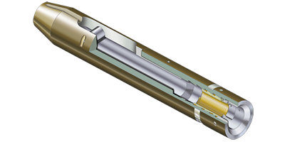
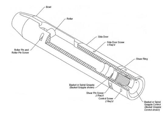
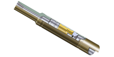
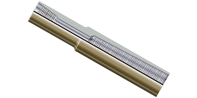
One option is a side-door overshot as shown in Figure 1. This method is similar to a regular overshot, except that it features a removable side door, so that the tool can be put together around the wireline at the well head itself. It is then possible to run the tool on some tubing or on the drillpipe, downhole alongside the wireline in order to make direct contact with the tool. This stops the wireline from being at risk of parting.
It is not recommended that side-door overshots are used with deep open hole intervals. This is because it introduces the potential for keyseating, or differential sticking in the mud cake.
Throughout modern drilling, the most successful method to retrieve stuck logging tools is through the cut-and-thread method. This involves cutting the wireline at the surface, and then threading it through a pipe string while the pipe is lowered, until it engages with the logging tool. The line must be secured at the surface, and rope sockets need to be fitted to each end to form a spearhead both emerging from the top of the well, and a spearhead overshot at the logging end. A stand of pipe will then be hung in the derrick, allowing enough of an overshot at the bottom to catch the logging tool, or at least the wireline rope socket. When the upper end of the line is spooled down through the interior of the pipe until the overshot connects with the spearhead at the bottom, then the pipe will be run into the hole. This is repeated with additional stands until the bottom of the string is close enough to the fish. When this is achieved, the spearhead overshot can be disengaged and the overshot can be circulated clean, before it engages with the tool. When the fish has been grasped securely, the wireline will be pulled free from the rope socket, and then spooled out of the hole, and the tool itself recovered with the fishing string. Although the cut-and-thread method takes a lot of time, and comes with a certain amount of risk, it vastly improves the chances of recovering the wireline and tool fully, and is much quicker than trying to engage with the wireline in an open hole.
If it is not possible to use either a side-door overshot or a cut-and-thread, then an alternative is to break the weakpoint, and then recover the cable and use the drill pipe to fish for the logging tool. If tool recovery is not an option, then a last resort is to push it to the very bottom of the hole, and then plug it using cement.

The Series 10 Sucker Rod Overshot is a small, rugged tool designed for engaging and retrieving sucker rods, couplings, and other items from inside tubing strings.
Series 20 Short Catch Sucker Rod Overshots are designed for conditions when sucker rods, couplings, and other portions of a fish are too short for retrieval with a standard overshot.
The Hydraulic Release Overshot was designed to aid in the recovery of a stuck fish in a horizontal drilling application where normal rotation for release is not obtainable.
The Series 150 Releasing and Circulating Overshot consists of three main external parts: a Top Sub, a Bowl, and a Guide. Internal catch and pack-off parts are determined by the diameter of the fish. Each assembly is designed for a maximum catch diameter.
A Series 160 Side Door Overshot is recommended when fishing for cable tools or conductor lines in cased holes. The side door overshot is run in on tubing or drill pipe.
The Superior Hydraulic Jar is a straight pull, up only, jarring tool that utilizes a special valve section to meter oil from one side of the piston to the other side. This allows for controlled jarring action during stuck fish recovery.
The Z Type Hydraulic Jar is used for light drilling, fishing, coring, reaming, testing, side tracking, and washover operations. This straight-pull jar combines the principles of mechanics and hydraulics in a simple to assemble, easy to operate design.
The Bi-Directional Coiled Tubing Jar is designed to hit upward and downward blows. It can be dressed to only hit up or down. These tools’ small outside diameters and shorter lengths make them ideal for milling, drilling, workover, remedial, or completion operations, especially in vertical, deviated, and ultradeep wellbores.
The Casing Roller repairs and restores dented, collapsed, or buckled tubing or casing of any size and weight to its original inside diameter and roundness.
Arctic Weather 85-Ton and 120-Ton Power Swivels are enclosed in insulated, 20-foot metal containers. The containers have adjustable louvers to allow operation in warmer temperatures. Two bi-fold doors on one side and double doors at the back permit complete access.
The arctic weather package also features deicer injector to prevent them from icing. Fuel and hydraulic tank heaters, and a hydraulic powered hose reel. One of the back doors features a hose window for routing hoses out of the container. To retain heat, the hose window is fitted with rubber flaps and a metal door on separate skid that is pulled in and out of the container by a dual drum hydraulic winch.
Note: *Cased Hole Only. The Chart above is a guide-line only and should be used as a rule of thumb; the final decision is that of the Customer; 4” Pin-up drill pipe is an option inside 7” casing, discuss
with Fishing Tool Manager for guidance. Consult with a EOFR Fishing Manager when requirements do not fall within the guide line shown; Bottom Hole Assemblies (BHA) also should be considered
* All pull loads listed are based on a magnet engaging a flat surface covering the entire face of the magnet. “Pick up” capability will be reduced considerably
The present invention generally relates to equipment used for removing downhole tools that are stuck in an oil or gas well. In particular, the present invention relates to an improved spear head overshot for use as part of a cable-guided fishing assembly used to remove downhole tools that have become stuck in an oil or gas well.
For situations in which the stuck tool is still attached to an intact wireline, either a cable-guided fishing method (also known as the “cut and strip” method) or a side-door overshot method is typically used to retrieve the tool. The cable-guided fishing method is typically used for deep, open-hole situations or when a radioactive instrument is stuck in the hole. For these situations, the cable-guided fishing method is a safe method that offers a high probability of success. In particular, the cable-guided fishing method allows retrieval of the stuck tool while the tool remains attached to the cable, thereby minimizing or removing the possibility that the tool will fall down the well during the fishing operation, and allowing for the well bore to be cleared with a minimum of downtime. Further, in some instances, through the use of the cable-guided fishing method, the expensive multi-conductor cable can be salvaged.
The cable-guided fishing method is performed with a special set of tools, hereinafter referred to as the “fishing assembly.” The fishing assembly typically comprises a cable hanger with a T-bar, a spearhead rope socket, a rope socket, one or more sinker bars, a spearhead overshot, and a “C” plate. To use the fishing assembly, the individual components of the assembly are assembled together in a series of steps. Specifically, a typical procedure for assembling the individual components of the fishing assembly is as follows (refer to FIG. 1 for a depiction of the individual components of the fishing assembly in their relative positions during and after assembly): (1) a light pulling force is exerted on the wireline to remove any slack;
(9) the spear head overshot (E) is then engaged with the spear head rope socket (B), and a “test strain” is exerted on the assembly by “pulling” on the wireline to ensure that the components are properly connected;
(10) with the spear head overshot (E) engaged with the spear head rope socket (B), the wireline is then “pulled” to exert a force sufficient to raise the cable hanger (A) so that it can be removed from the assembly;
In operation, the fishing assembly fishes the stuck tool out of the well in a series of steps. Specifically, the following steps are typical of the operation of the fishing assembly (refer to FIG. 2 for a depiction of the individual components of the fishing assembly in their relative positions during operation): (1) the spear head overshot (E) is disconnected from the spear head rope socket (B) and raised up to the derrick man;
(2) the derrick man will then thread the spear head overshot (E) and sinker bar (D) through the first stand of pipe (G) to be run into the well as part of the fishing operation;
(4) the spear head overshot (E) should then be connected to the spear head rope socket (B), a light strain taken on the cable, and the “C” Plate (F in FIG. 1) removed;
(8) the derrick man threads the spear head overshot (E) and sinker bar (D) through the next stand of pipe (I), which in turn is picked up by the driller and suspended over the well head through use of the rig"s elevator (J);
(9) the spear head overshot (E) is connected to the spear head rope socket (B), the “C” Plate is removed, and the second stand of pipe (I) is stabbed into and made up to the first stand of pipe (G) and run into the well bore;
(10) the “C” Plate is replaced, the spear head overshot (E) is again disconnected and raised up to the derrick man, and the procedure is repeated until enough pipe has been run into the well to contact and free the stuck tool;
While the fishing assembly and method of use described in the preceding paragraphs has proven to be quite successful, difficulties have arisen with some of the prior art components of the fishing assembly. For example, prior art spear head overshots typically require a three-prong “wedge” release tool to disengage the spear head from the spear head overshot. This three-prong “wedge” release tool requires rig floor personnel to effectively wrap the release tool around the spear head overshot, thereby putting the rig floor personnel in extremely close proximity to the fishing assembly and associated tubing. As one of ordinary skill in the art will recognize, close proximity to the fishing assembly and tubing presents a significant safety concern. Accordingly, the following improved spear head overshot eliminates the need for this close proximity and provides a safer and more efficient means to disengage the spear head from the spear head overshot.
This invention relates to an improved spear head overshot. In a preferred embodiment of the present invention, the spear head overshot comprises a hollow outer tubular. An oversized guide may be attached to the outer tubular at the lower end of the spear head overshot. Moving upward from the lower end, the hollow outer tubular contains two pivot lugs. The pivot lugs run parallel to each other and are effectively comprised of three portions: the “jaws”; the pivot rods; and the release points. The jaws are located at the lowermost portion of the pivot lugs and extend inwardly towards the hollow center of the outer tubular. The pivot rods extend longitudinally along a rectangular cutout section of the outer diameter of the outer tubular and effectively connect the jaws to the release points. The release points are located at the uppermost portion of the pivot lugs and extend through a square-shaped cutout section of the outer diameter of the outer tubular. That portion of the release points that extends through the square-shaped cutout sections of the outer tubular exhibits a recessed circular geometry.
In a typical fishing operation, a spear head is inserted into the lower end of the spear head overshot of the present invention. As the spear head enters the lower end of the spear head overshot, the jaws of the pivot lugs are forced outward (and the release points are inversely forced inward) until the arrowhead portion of the spear head passes beyond the jaws. As the spear head passes, the jaws essentially snap back into their initial position due to the contact of the actuator slide with the release points and the downward bias of the wave spring. At this point, the spear head is engaged within the spear head overshot.
At this point in the fishing operation, an upward force is exerted on the spear head overshot. This upward force, in combination with the static force being exerted on the spear head (from the stuck down hole tool), causes the lower shoulder of the arrowhead portion of the spear head to abut the upper shoulders of the jaws. As the upward force on the spearhead overshot increases, the spear head forces the jaws, and thereby the pivot lugs, longitudinally downward into contact with an upper shoulder of the outer tubular. This movement of the pivot lugs also forces the pivot mandrel longitudinally downward (overcoming the bias of the compression spring) due to the abutment of opposing shoulders of the pivot lugs and the pivot mandrel. The downward movement of the pivot lugs also forces two lips on the lower portion of the jaws to tuck in against the inner diameter of the outer tubular. These lips prohibit the disengagement of the spear head from the spear head overshot while the assembly is in tension.
When the upward pulling force is no longer acting on the spear head overshot, the movement of the internal components as described above is essentially reversed. To remove the spear head, a two-pronged release tool is manually placed in contact with the spear head overshot such that the two prongs engage the two release points of the pivot lugs. The two pronged release tool essentially squeezes the release points inward. As the release points of the pivot lugs are forced inward, the jaws of the pivot lugs are inversely forced outward. As such, the arrowhead portion of the spear head may pass by the jaws without contact. Accordingly, the spear point may be lowered and disengaged from within the spear head overshot. The two-pronged release tool (not shown) is then manually disengaged from the spear head overshot, which causes the wave spring to again force the actuator slide downward, which subsequently causes the actuator slide to again force the release points outward.
FIG. 2 is a side view of a typical cable-guided fishing assembly showing the various components of such assembly in their respective positions within tubular members during operation.
FIG. 7 is a cross-sectional view of a spear head engaged within the overshot of the present invention. FIG. 7 further illustrates the spear head overshot actuated such that the spear head may be removed from the overshot.
The following example is included to demonstrate a preferred embodiment of the present invention. It should be appreciated by those of skill in the art that the apparatus and method disclosed in the example that follows represent techniques discovered by the inventors to function well in the practice of the invention, and thus can be considered to constitute a preferred mode for its practice. However, those of skill in the art should, in light of the present disclosure, appreciate that many changes can be made in the specific embodiment which is disclosed and still obtain a like or similar result without departing from the spirit and scope of the invention.
FIGS. 3 through 5 illustrate a preferred embodiment of the spear head overshot of the present invention. While the spear head overshot is preferably comprised of steel, any material capable of withstanding the significant forces imposed on the spear head overshot during use may be used. Referring specifically to FIG. 3, the spear head over shot (1) comprises a hollow outer tubular (1 a). The upper end of the outer tubular contains a set of female threads for connecting the spear head overshot to another component of the cable guide fishing assembly, typically a sinker bar. Attached to the outer tubular (1 a) at the lower end is an oversized guide (2). The oversized guide (2) is preferably attached to the outer tubular (1 a) using one or more spring pins (3), however any suitable attachment means may be used. As shown best in FIGS. 4 and 5, a wrench flat (1 b) is located on the upper portion of the outer tubular (1 a).
Referring generally to the “fishing” operation described in the “BACKGROUND” section above, a spear head (19), as shown in FIG. 6, is inserted into the lower end of the spear head overshot (1) of the present invention. As the spear head (19) enters the lower end of the spear head overshot (1), the jaws (5) of the pivot lugs (4) are forced outward (and the release points (7) are inversely forced inward) until the arrowhead portion (20) of the spear head (19) passes beyond the jaws (5). As the spear head (19) passes, the jaws (5) essentially snap back into their initial position (as shown in FIG. 6) due to the contact of the actuator slide (17) with the release points (7) and the downward bias of the wave spring (18). At this point, the spear head (19) is engaged within the spear head overshot (1).
As further described in the fishing operation above, an upward force is then exerted on the spear head overshot (1). This upward force, in combination with the static force being exerted on the spear head (19) (from the stuck down hole tool), causes the lower shoulder (21) of the arrowhead portion (20) of the spear head (19) to abut the upper shoulders (22) of the jaws (5). As the upward force on the spearhead overshot (1) increases, the spear head (19) forces the jaws (5), and thereby the pivot lugs (4), longitudinally downward into contact with an upper shoulder (23) of the outer tubular (1 a). This movement of the pivot lugs (4) also forces the pivot mandrel (10) longitudinally downward (overcoming the bias of the compression spring (12)) due to the abutment of opposing shoulders (24, 25) of the pivot lugs (4) and the pivot mandrel (10). The downward movement of the pivot lugs (4) also forces two lips (26) on the lower portion of the jaws (5) to essentially tuck in against the inner diameter of the outer tubular (1 a). These lips (26) prohibit the disengagement of the spear head (19) from the spear head overshot (1) while the assembly is in tension.
When the upward pulling force is no longer acting on the spear head overshot (1), the movement of the internal components as described above is essentially reversed. The spear head (19), and thereby the pivot lugs (4), move upwardly once again. At this point, the assembly is no longer in tension, and the spear head (19) can be removed from the spear head overshot (1). To remove the spear head (19), a two-pronged release tool (not shown) is preferably utilized. The two-pronged release tool is manually placed in contact with the spear head overshot (1) such that the two prongs engage the two release points (7) of the pivot lugs (4). As shown in FIG. 7, the two-pronged release tool (not shown) essentially squeezes the release points (7) inward. As the release points (7) of the pivot lugs (4) are forced inward, the jaws (5) of the pivot lugs (4) are inversely forced outward. As such, the arrowhead portion (20) of the spear head (19) may pass by the jaws (5) without contact. Accordingly, the spear point (19) may be lowered and disengaged from within the spear head overshot (1). The two-pronged release tool (not shown) is then manually disengaged from the spear head overshot (1), which causes the wave spring (18) to again force the actuator slide (17) downward, which subsequently causes the actuator slide (17) to again force the release points (7) outward.
The process of engaging and disengaging the spear head (19) from within the spear head overshot (1) may be repeated as many times as necessary according to the specific parameters of the fishing operation.

Are you looking for a 170 L-class CO2 incubator that provides flexibility for the future, makes monitoring and documentation easy and provides optimized growth conditions, even for your sensitive cells? A CO2 incubator that also saves money and is produced with highest quality standards? Discover the new Eppendorf CellXpert C170i. Features include: 1)In-field changeable door handle position 2)Two access ports for user-validated devices 3)For pH-stability of medium: drift-free CO2 dual-channel IR sensor 3) Uniform temperature: multiple temperature sensors and 27-point validation 4)Fast temperature and CO2 recovery in less than 5 minutes without overshoot 5)Vibration and turbulence protection by fanless design 6)180 °C High temperature disinfection standard 7)Seamless, deep-drawn chamber; fanless design 8)High capacity/footprint ratio; up to 25% more usable volume 9)No internal replacement parts (e.g. HEPA filters, UV-lamp) 10)ow gas consumption with smart gas control 11)BMS interface standard; 4-20 mA interface optional 12)Two front USB-ports; Ethernet 13)Advanced user interface (touchscreen) 14)Magnetic inner/outer door closing and 15)Programmable tasks; user management

About this time, the invention of the Whitehead torpedo posed a control problem that required accurate control of the running depth. Use of a depth pressure sensor alone proved inadequate, and a pendulum that measured the fore and aft pitch of the torpedo was combined with depth measurement to become the pendulum-and-hydrostat control. Pressure control provided only a proportional control that, if the control gain was too high, would become unstable and go into overshoot with considerable instability of depth-holding. The pendulum added what is now known as derivative control, which damped the oscillations by detecting the torpedo dive/climb angle and thereby the rate-of-change of depth.
Consider a robotic armelectric motor may lift or lower the arm, depending on forward or reverse power applied, but power cannot be a simple function of position because of the inertial mass of the arm, forces due to gravity, external forces on the arm such as a load to lift or work to be done on an external object.
The obvious method is proportional control: the motor current is set in proportion to the existing error. However, this method fails if, for instance, the arm has to lift different weights: a greater weight needs a greater force applied for the same error on the down side, but a smaller force if the error is low on the upside. That"s where the integral and derivative terms play their part.
A derivative term does not consider the magnitude of the error (meaning it cannot bring it to zero: a pure D controller cannot bring the system to its setpoint), but the rate of change of error, trying to bring this rate to zero. It aims at flattening the error trajectory into a horizontal line, damping the force applied, and so reduces overshoot (error on the other side because of too great applied force).
One way to determine the parameters for the first-order process is using the 63.2% method. In this method, the process gain (kp) is equal to the change in output divided by the change in input. The dead time (θ) is the amount of time between when the step change occurred and when the output first changed. The time constant (τp) is the amount of time it takes for the output to reach 63.2% of the new steady-state value after the step change. One downside to using this method is that it can take a while to reach a new steady-state value if the process has large time constants.
For example, a PID loop is used to control the temperature of an electric resistance furnace where the system has stabilized. Now when the door is opened and something cold is put into the furnace the temperature drops below the setpoint. The integral function of the controller tends to compensate for error by introducing another error in the positive direction. This overshoot can be avoided by freezing of the integral function after the opening of the door for the time the control loop typically needs to reheat the furnace.
In many cases, the manipulated variable output by the PID controller is a dimensionless fraction between 0 and 100% of some maximum possible value, and the translation into real units (such as pumping rate or watts of heater power) is outside the PID controller. The process variable, however, is in dimensioned units such as temperature. It is common in this case to express the gain K
Leg length in miles if DME or RNAV is to be used. (Leg length will be specified in minutes on pilot request or if the controller considers it necessary.)
Holding patterns may be restricted to a maximum speed. The speed restriction is depicted in parenthesis inside the holding pattern on the chart: for example, (175). The aircraft should be at or below the maximum speed prior to initially crossing the holding fix to avoid exiting the protected airspace. Pilots unable to comply with the maximum airspeed restriction should notify ATC.
Parallel Procedure.When approaching the holding fix from anywhere in sector (a), the parallel entry procedure would be to turn to a heading to parallel the holding course outbound on the nonholding side for one minute, turn in the direction of the holding pattern through more than 180 degrees, and return to the holding fix or intercept the holding course inbound.
Teardrop Procedure.When approaching the holding fix from anywhere in sector (b), the teardrop entry procedure would be to fly to the fix, turn outbound to a heading for a 30 degree teardrop entry within the pattern (on the holding side) for a period of one minute, then turn in the direction of the holding pattern to intercept the inbound holding course.
Nonstandard Holding Pattern. Fix end and outbound end turns are made to the left. Entry procedures to a nonstandard pattern are oriented in relation to the 70 degree line on the holding side just as in the standard pattern.
Use of RNAV Distance in lieu of DME Distance.Substitution of RNAV computed distance to or from a NAVAID in place of DME distance is permitted when holding. However, the actual holding location and pattern flown will be further from the NAVAID than designed due to the lack of slant range in the position solution (see FIG ENR 1.5-6). This may result in a slight difference between RNAV distance readout in reference to the NAVAID and the DME readout, especially at higher altitudes. When used solely for DME substitution, the difference between RNAV distance to/from a fix and DME slant range distance can be considered negligible and no pilot action is required.
All holding, including holding defined on an RNAV or RNP procedure, is based on the conventional NAVAID holding design criteria, including the holding protected airspace construction. There are differences between the holding entry and flight track assumed in conventional holding pattern design and the entry and track that may be flown when RNAV guidance is used to execute holding. Individually, these differences may not affect the ability of the aircraft to remain within holding pattern protected airspace. However, cumulatively, they can result in deviations sufficient to result in excursions up to limits of the holding pattern protected airspace, and in some circumstances beyond protected airspace. The following difference and considerations apply when an RNAV system furnishes the lateral guidance used to fly a holding pattern:
The holding protected airspace is based on the assumption that the aircraft will fly-over the holding fix upon initial entry. RNAV systems may execute a “fly-by” turn when approaching the holding fix prior to entry. A “fly-by” turn during a direct entry from the holding pattern side of holding course may result in excursions beyond protected airspace, especially as the intercept angle and ground speed increase.
RNAV systems are not able to alert the pilot for excursions outside of holding pattern protected airspace since the dimensions of this airspace are not included in the navigation database. In addition, the dimensions of holding pattern protected airspace vary with altitude for a charted holding pattern, even when the hold is used for the same application. Close adherence to the pilot actions described in this section reduce the likelihood of exceeding the boundary of holding pattern protected airspace when using RNAV lateral guidance to conduct holding.
Determine entry turn from aircraft heading upon arrival at the holding fix; +/- 5 degrees in heading is considered to be within allowable good operating limits for determining entry. When using RNAV lateral guidance for holding, it is permissible to allow the system to compute the holding entry.
The controller will attempt to detect any holding aircraft that stray outside the holding airspace and will assist any detected aircraft to return to the assigned airspace.
STAR procedures may have mandatory speeds and/or crossing altitudes published. Other STARs may have planning information depicted to inform pilots what clearances or restrictions to “expect.” “Expect” altitudes/speeds are not considered STAR procedures crossing restrictions unless verbally issued by ATC. Published speed restrictions are independent of altitude restrictions and are mandatory unless modified by ATC. Pilots should plan to cross waypoints with a published speed restriction, at the published speed, and should not exceed this speed past the associated waypoint unless authorized by ATC or a published note to do so.
Pilots navigating on, or navigating a published route inbound to, a STAR procedure must maintain last assigned altitude until receiving authorization to descend so as to comply with all published/issued restrictions. This authorization will contain the phraseology “DESCEND VIA.” If vectored or cleared to deviate off a STAR, pilots must consider the STAR canceled, unless the controller adds “expect to resume STAR”; pilots should then be prepared to rejoin the STAR at a subsequent fix or procedure leg. If a descent clearance has been received that included a crossing restriction, pilots should expect the controller to issue an altitude to maintain. If the STAR contains published altitude and/or speed restrictions, those restrictions are canceled and pilots will receive an altitude to maintain and, if necessary, a speed.
Minimum en route altitudes (MEA) are not considered restrictions; however, pilots must remain above all MEAs, unless receiving an ATC instruction to descend below the MEA.
Controllers will consider the long line disseminated weather from an automated weather system at an uncontrolled airport as trend and planning information only and will rely on the pilot for current weather information for the airport. If the pilot is unable to receive the current broadcast weather, the last long-line disseminated weather will be issued to the pilot. When receiving IFR services, the pilot/aircraft operator is responsible for determining if weather/visibility is adequate for approach/landing.
RNAV aircraft may be issued a clearance direct to the FAF that is also charted as an IAF, in which case the pilot is expected to execute the depicted procedure turn or hold-in-lieu of procedure turn. ATC will not issue a straight-in approach clearance. If the pilot desires a straight-in approach, they must request vectors to the final approach course outside of the FAF or fly a published “NoPT” route. When visual approaches are in use, ATC may clear an aircraft direct to the FAF.
Selection of “Vectors-to-Final” or “Vectors” option for an instrument approach may prevent approach fixes located outside of the FAF from being loaded into an RNAV system. Therefore, the selection of these options is discouraged due to increased workload for pilots to reprogram the navigation system.
The pilot may elect to use the procedure turn or hold-in-lieu-of-PT when it is not required by the procedure, but must first receive an amended clearance from ATC. If the pilot is uncertain whether the ATC clearance intends for a procedure turn to be conducted or to allow for a straight-in approach, the pilot must immediately request clarification from ATC (14 CFR Section 91.123).On U.S. Government charts, a barbed arrow indicates the maneuvering side of the outbound course on which the procedure turn is made. Headings are provided for course reversal using the 45 degree type procedure turn. However, the point at which the turn may be commenced and the type and rate of turn is left to the discretion of the pilot (limited by the charted remain within xx NM distance). Some of the options are the 45 degree procedure turn, the racetrack pattern, the teardrop procedure turn, or the 80 degree ↔ 260 degree course reversal. Racetrack entries should be conducted on the maneuvering side where the majority of protected airspace resides. If an entry places the pilot on the non-maneuvering side of the PT, correction to intercept the outbound course ensures remaining within protected airspace. Some procedure turns are specified by procedural track. These turns must be flown exactly as depicted.
A teardrop procedure or penetration turn may be specified in some procedures for a required course reversal. The teardrop procedure consists of departure from an initial approach fix on an outbound course followed by a turn toward and intercepting the inbound course at or prior to the intermediate fix or point. Its purpose is to permit an aircraft to reverse direction and lose considerable altitude within reasonably limited airspace. Where no fix is available to mark the beginning of the intermediate segment, it must be assumed to commence at a point 10 miles prior to the final approach fix. When the facility is located on the airport, an aircraft is considered to be on final approach upon completion of the penetration turn. However, the final approach segment begins on the final approach course 10 miles from the facility.
Aircraft that will execute a side‐step maneuver will be cleared for a specified approach procedure and landing on the adjacent parallel runway. Example, “cleared ILS runway 7 left approach, side‐step to runway 7 right.” Pilots are expected to commence the side‐step maneuver as soon as possible after the runway or runway environment is in sight. Compliance with minimum altitudes associated with stepdown fixes is expected even after the side-step maneuver is initiated.
A pilot who chooses an alternative method when it is necessary to maneuver at a speed that exceeds the category speed limit (for example, where higher category minimums are not published) should consider the following factors that can significantly affect the actual ground track flown:
Wind speed and direction. For example, it is not uncommon to maneuver the aircraft to a downwind leg where the groundspeed will be considerably higher than the indicated airspeed. Pilots must carefully plan the initiation of all turns to ensure that the aircraft remains within the circling approach protected area.
Pilot technique. Pilots frequently have many options with regard to flightpath when conducting circling approaches. Sound planning and judgment are vital to proper execution. The lateral and vertical path to be flown should be carefully considered using current weather and terrain information to ensure that the aircraft remains within the circling approach protected area.
Obstacle Clearance.Final approach obstacle clearance is provided from the start of the final segment to the runway or missed approach point, whichever occurs last. Side‐step obstacle protection is provided by increasing the width of the final approach obstacle clearance area.
Circling approach protected areas are defined by the tangential connection of arcs drawn from each runway end (see FIG ENR 1.5-14). Circling approach protected areas developed prior to late 2012 used fixed radius distances, dependent on aircraft approach category, as shown in the table on page B2 of the U.S. TPP. The approaches using standard circling approach areas can be identified by the absence of the “negative C" symbol on the circling line of minima. Circling approach protected areas developed after late 2012 use the radius distance shown in the table on page B2 of the U.S. TPP, dependent on aircraft approach category, and the altitude of the circling MDA, which accounts for true airspeed increase with altitude. The approaches using expanded circling approach areas can be identified by the presence of the “negative C" symbol on the circling line of minima (see FIG ENR 1.5-15). Because of obstacles near the airport, a portion of the circling area may be restricted by a procedural note; for example, “Circling NA E of RWY 17-35.” Obstacle clearance is provided at the published minimums (MDA) for the pilot who makes a straight-in approach, side-steps, or circles. Once below the MDA the pilot must see and avoid obstacles. Executing the missed approach after starting to maneuver usually places the aircraft beyond the MAP. The aircraft is clear of obstacles when at or above the MDA while inside the circling area, but simply joining the missed approach ground track from the circling maneuver may not provide vertical obstacle clearance once the aircraft exits the circling area. Additional climb inside the circling area may be required before joining the missed approach track. See ENR 1.5-27., Missed Approach, for additional considerations when starting a missed approach at other than the MAP.
Precision Obstacle Free Zone (POFZ). A volume of airspace above an area beginning at the runway threshold, at the threshold elevation, and centered on the extended runway centerline. The POFZ is 200 feet (60m) long and 800 feet (240m) wide. The POFZ must be clear when an aircraft on a vertically guided final approach is within 2 nautical miles of the runway threshold and the official weather observation is a ceiling below 250 feet or visibility less than 3/4 statute mile (SM) (or runway visual range below 4,000 feet). If the POFZ is not clear, the MINIMUM authorized height above touchdown (HAT) and visibility is 250 feet and 3/4SM. The POFZ is considered clear even if the wing of the aircraft holding on a taxiway waiting for runway clearance penetrates the POFZ; however, neither the fuselage nor the tail may infringe on the POFZ. The POFZ is applicable at all runway ends including displaced thresholds. (See FIG ENR 1.5-16.)
Side-Step Maneuver Minimums. Landing minimums for a side-step maneuver to the adjacent runway will normally be higher than the minimums to the primary runway.
Circling Minimums.In some busy terminal areas, ATC may not allow circling and circling minimums will not be published. Published circling minimums provide obstacle clearance when pilots remain within the appropriate area of protection. Pilots should remain at or above the circling altitude until the aircraft is continuously in a position from which a descent to a landing on the intended runway can be made at a normal rate of descent using normal maneuvers. Circling may require maneuvers at low altitude, at low airspeed, and in marginal weather conditions. Pilots must use sound judgment, have an in-depth knowledge of their capabilities, and fully understand the aircraft performance to determine the exact circling maneuver since weather, unique airport design, and the aircraft position, altitude, and airspeed must all be considered. The following basic rules apply:
Maneuver the shortest path to the base or downwind leg, as appropriate, considering existing weather conditions. There is no restriction from passing over the airport or other runways.
It should be recognized that circling maneuvers may be made while VFR or other flying is in progress at the airport. Standard left turns or specific instruction from the controller for maneuvering must be considered when circling to land.
In some cases, other types of navigation systems including radar may be required to execute other portions of the approach or to navigate to the IAF (e.g., an NDB procedure turn to an ILS, an NDB in the missed approach, or radar required to join the procedure or identify a fix). When radar or other equipment is required for procedure entry from the en route environment, a note will be charted in the planview of the approach procedure chart (for example, RADAR REQUIRED or ADF REQUIRED). When radar or other equipment is required on portions of the procedure outside the final approach segment, including the missed approach, a note will be charted in the notes box of the pilot briefing portion of the approach chart (for example, RADAR REQUIRED or DME REQUIRED). Notes are not charted when VOR is required outside the final approach segment. Pilots should ensure that the aircraft is equipped with the required NAVAID(s) in order to execute the approach, including the missed approach.
Approaches used for simultaneous (parallel) independent and simultaneous close parallel operations procedurally require descending on the glideslope from the altitude at which the approach clearance is issued (refer to ENR 1.5-19. and ENR 1.5-20.). For simultaneous close parallel (PRM) approaches, the Attention All Users Page (AAUP) may publish a note which indicates that descending on the glideslope/glidepath meets all crossing restrictions. However, if no such note is published, and for simultaneous independent approaches (4300 and greater runway separation) where an AAUP is not published, pilots are cautioned to monitor their descent on the glideslope/path outside of the PFAF to ensure compliance with published crossing restrictions during simultaneous operations.
Altitude restrictions depicted at stepdown fixes within the final approach segment are applicable only when flying a Non-Precision Approach to a straight-in or circling line of minima identified as an MDA. These altitude restrictions may be annotated with a note “LOC only” or “LNAV only.” Stepdown fix altitude restrictions within the final approach segment do not apply to pilots using Precision Approach (ILS) or Approach with Vertical Guidance (LPV, LNAV/VNAV) lines of minima identified as a DA, since obstacle clearance on these approaches is based on the aircraft following the applicable vertical guidance. Pilots are responsible for adherence to stepdown fix altitude restrictions when outside the final approach segment (i.e., initial or intermediate segment), regardless of which type of procedure the pilot is flying. (See FIG ENR 1.5-17).
U.S. Government charts depict TAAs using icons located in the plan view outside the depiction of the actual approach procedure. (See FIG ENR 1.5-22). Use of icons is necessary to avoid obscuring any portion of the “T” procedure (altitudes, courses, minimum altitudes, etc.). The icon for each TAA area will be located and oriented on the plan view with respect to the direction of arrival to the approach procedure, and will show all TAA minimum altitudes and sector/radius subdivisions. The IAF for each area of the TAA is included on the icon where it appears on the approach to help the pilot orient the icon to the approach procedure. The IAF name and the distance of the TAA area boundary from the IAF are included on the outside arc of the TAA area icon.
TAAs may be modified from the standard size and shape to accommodate operational or ATC requirements. Some areas may be eliminated, while the other areas are expanded. The “T” design may be modified by the procedure designers where required by terrain or ATC considerations. For instance, the “T” design may appear more like a regularly or irregularly shaped “Y,” upside down “L,” or an “I.”
Because of differences in the areas considered for MVA, and those applied to other minimum altitudes, and the ability to isolate specific obstacles, some MVAs may be lower than the nonradar Minimum En Route Altitudes (MEAs), Minimum Obstruction Clearance Altitudes (MOCAs) or other minimum altitudes depicted on charts for a given location. While being radar vectored, IFR altitude assignments by ATC will be at or above MVA.
Circling MDA. The circling MDA will provide 300 foot obstacle clearance within the area considered for obstacle clearance and may be lower than the LNAV/VNAV DA, but never lower than the straight in LNAV MDA. This may occur when different controlling obstacles are used or when other controlling factors force the LNAV MDA to be higher than 250 feet above the LNAV OCS. In FIG ENR 1.5-28, the required obstacle clearance for both the LNAV and Circle resulted in the same MDA, but lower than the LNAV/VNAV DA. FIG ENR 1.5-29 provides an illustration of this type of situation.
On a straight-in nonprecision IAP, descent below the MDA between the VDP and the MAP may be inadvisable or impossible. Aircraft speed, height above the runway, descent rate, amount of turn, and runway length are some of the factors which must be considered by the pilot to determine if a safe descent and landing can be accomplished.
The threshold crossing height (TCH) used to compute the descent angle is published with the VDA. The VDA and TCH information are charted on the profile view of the IAP following the fix (FAF/stepdown) used to compute the VDA. If no PA/APV IAP is established to the same runway, the VDA will be equal to or higher than the glide path angle of the VGSI installed on the same runway provided it is within instrument procedure criteria. A chart note will indicate if the VGSI is not coincident with the VDA. Pilots must be aware that the published VDA is for advisory information only and not to be considered instrument procedure derived vertical guidance. The VDA solely offers an aid to help pilots establish a continuous, stabilized descent during final approach.
The stabilized approach may be performed by reference to vertical navigation information provided by WAAS or LNAV/VNAV systems; or for LNAV-only systems, by the pilot determining the appropriate aircraft attitude/groundspeed combination to attain a constant rate descent which best emulates the published angle. To aid the pilot, U.S. Government Terminal Procedures Publication charts publish an expanded Rate of Descent Table on the inside of the back hard cover for use in planning and executing precision descents under known or approximate groundspeed conditions.
A Precision Approach (PAR) is one in which a controller provides highly accurate navigational guidance in azimuth and elevation to a pilot. Pilots are given headings to fly to direct them to and keep their aircraft aligned with the extended centerline of the landing runway. They are told to anticipate glidepath interception approximately 10 to 30 seconds before it occurs and when to start descent. The published decision height will be given only if the pilot requests it. If the aircraft is observed to deviate above or below the glidepath, the pilot is given the relative amount of deviation by use of terms “slightly” or “well” and is expected to adjust the aircraft"s rate of descent to return to the glidepath. Trend information is also issued with respect to the elevation of the aircraft and may be modified by the terms “rapidly” and “slowly”; e.g., “well above glidepath, coming down rapidly.” Range from touchdown is given at least once each mile. If an aircraft is observed by the controller to proceed outside of specified safety zone limits in azimuth and/or elevation and continues to operate outside these prescribed limits, the pilot will be directed to execute a missed approach or to fly a specified course unless the pilot has the runway environment (runway, approach lights, etc.) in sight. Navigational guidance in azimuth and elevation is provided the pilot until the aircraft reaches the published decision height (DH). Advisory course and glidepath information is furnished by the controller until the aircraft passes over the landing threshold, at which point the pilot is advised of any deviation from the runway centerline. Radar service is automatically terminated upon completion of the approach.
A Surveillance Approach (ASR) is one in which a controller provides navigational guidance in azimuth only. The pilot is furnished headings to fly to align the aircraft with the extended centerline of the landing runway. Since the radar information used for a surveillance approach is considerably less precise than that used for a precision approach, the accuracy of the approach will not be as great, and higher minimums will apply. Guidance in elevation is not possible but the pilot will be advised when to commence descent to the minimum descent altitude (MDA) or, if appropriate, to an intermediate “step down fix” minimum crossing altitude and subsequently to the prescribed MDA. In addition, the pilot will be advised of the location of the missed approach point (MAP) prescribed for the procedure and the aircraft"s position each mile on final from the runway, airport/heliport, or MAP, as appropriate. If requested by the pilot, recommended altitudes will be issued at each mile, based on the descent gradient established for the procedure, down to the last mile that is at or above the MDA. Normally, navigational guidance will be provided until the aircraft reaches the MAP. Controllers will terminate guidance and instruct the pilot to execute a missed approach unless at the MAP the pilot has the runway, airport/heliport in sight or, for a helicopter point-in-space approach, the prescribed visual reference with the surface is established. Also, if at any time during the approach the controller considers that safe guidance for the remainder of the approach cannot be provided, the controller will terminate guidance and instruct the pilot to execute a missed approach. Similarly, guidance termination and missed approach will be effected upon pilot request, and for civil aircraft only, controllers may terminate guidance when the pilot reports the runway, airport/heliport, or visual surface route (point-in-space approach) in sight or otherwise indicates that continued guidance is not required. Radar service is automatically terminated at the completion of a radar approach.
If, after repeated advisories, the aircraft proceeds outside the PAR safety limit or if a radical deviation is observed, the pilot will be advised to execute a missed approach if not visual.
Requirements and Procedures. Besides system requirements and pilot procedures as identified in subparagraph 20.1.1 above, all pilots must have completed special training before accepting a clearance to conduct a PRM approach.
Some FMSs do not code waypoints inside of the FAF as part of the approach. Therefore, the depicted MAP on the charted IAP may not be included in the offset approach coding. Pilots utilizing those FMSs may identify the location of the waypoint by noting its distance from the FTP as published on the charted IAP. In those same FMSs, the straight-in SOIA approach will not display a waypoint inside the PFAF. The same procedures may be utilized to identify an uncoded waypoint. In this case, the location is determined by noting its distance from the runway waypoint or using an authorized distance as published on the charted IAP.
The point along the LDA, or other offset course, where the course separation with the adjacent ILS, or other straight-in course, reaches the minimum distance permitted to conduct closely spaced approaches. Typically that minimum distance will be 3,000 feet without the use of high update radar; with high update radar, course separation of less than 3,000 ft may be used when validated by a safety study. The altitude of the glide slope/glide path at that point determines the offset course approach decision altitude and is where the NTZ terminates. Maneuvering inside the DA is done in visual conditions.
The following are differences between widely spaced simultaneous approaches (at least 4,300 feet between the runway centerlines) and Simultaneous PRM close parallel approaches which are of importance to the pilot:Runway Spacing. Prior to PRM simultaneous close parallel approaches, most ATC-directed breakouts were the result of two aircraft in-trail on the same final approach course getting too close together. Two aircraft going in the same direction did not mandate quick reaction times. With PRM closely spaced approaches, two aircraft could be alongside each other, navigating on courses that are separated by less than 4,300 feet and as close as 3,000 feet. In the unlikely event that an aircraft “blunders” off its course and makes a worst case turn of 30 degrees toward the adjacent final approach course, closing speeds of 135 feet per second could occur that constitute the need for quick reaction. A blunder has to be recognized by the monitor controller, and breakout instructions issued to the endangered aircraft. The pilot will not have any warning that a breakout is imminent because the blundering aircraft will be on another frequency. It is important that, when a pilot receives breakout instructions, the assumption is made that a blundering aircraft is about to (or has penetrated the NTZ) and is heading toward his/her approach course. The pilot must initiate a breakout as soon as safety allows. While conducting PRM approaches, pilots must maintain an increased sense of awareness in order to immediately react to an ATC (breakout) instruction and maneuver (as instructed by ATC) away from a blundering aircraft.
Missed Approach Considerations. In order to conduct an EFVS operation, the EFVS must be operable. In the event of a failure of any required component of an EFVS at any point in the approach to touchdown, a missed approach is required. However, this provision does not preclude a pilot"s authority to continue an approach if continuation of an approach is considered by the pilot to be a safer course of action.
Other Vision Systems. Unlike an EFVS that meets the equipment requirements of 14 CFR § 91.176, a Synthetic Vision System (SVS) or Synthetic Vision Guidance System (SVGS) does not provide a real-time sensor image of the outside scene and also does not meet the equipment requirements for EFVS operations. A pilot cannot use a synthetic vision image on a head-up or a head-down display in lieu of natural vision to descend below DA/DH or MDA. An EFVS can, however, be integrated with an SVS, also known as a Combined Vision System (CVS). A CVS can be used to conduct EFVS operations if all of the requirements for an EFVS are satisfied and the SVS image does not interfere with the pilot"s ability to see the external scene, to identify the required visual references, or to see the sensor image.
The intent of the 30 degree intercept angle is to reduce the potential for overshoots of the final and to preclude side-by-side operations with one or both aircraft in a belly-up configuration during the turn-on.
CVFPs are charted visual approaches established for environmental/noise considerations, and/or when necessary for the safety and efficiency of air traffic operations. The approach charts depict prominent landmarks, courses, and recommended altitudes to specific runways. CVFPs are designed to be used primarily for turbojet aircraft.
Obstacle protection for missed approach is predicated on the missed approach being initiated at the decision altitude/decision height (DA/DH) or at the missed approach point and not lower than minimum descent altitude (MDA). A climb gradient of at least 200 feet per nautical mile is required, (except for Copter approaches, where a climb of at least 400 feet per nautical mile is required), unless a higher climb gradient is published in the notes section of the approach procedure chart. When higher than standard climb gradients are specified, the end point of the non-standard climb will be specified at either an altitude or a fix. Pilots must preplan to ensure that the aircraft can meet the climb gradient (expressed in feet per nautical mile) required by the procedure in the event of a missed approach, and be aware that flying at a higher than anticipated ground speed increases the climb rate requirement (feet per minute). Tables for the conversion of climb gradients (feet per nautical mile) to climb rate (feet per minute), based on ground speed, are included on page D1 of the U.S. Terminal Procedures booklets. Reasonable buffers are provided for normal maneuvers. However, no consideration is given to an abnormally early turn. Therefore, when an early missed approach is executed, pilots should, unless otherwise cleared by ATC, fly the IAP as specified on the approach plate to the missed approach point at or above the MDA or DH before executing a turning maneuver.
In the event a balked (rejected) landing occurs at a position other than the published missed approach point, the pilot should contact ATC as soon as possible to obtain an amended clearance. If unable to contact ATC for any reason, the pilot should attempt to re-intercept a published segment of the missed approach and comply with route and altitude instructions. If unable to contact ATC, and in the pilot"s judgment it is no longer appropriate to fly the published missed approach procedure, then consider either maintaining visual conditions if practicable and reattempt a landing, or a circle-climb over the airport. Should a missed approach become necessary when operating to an airport that is not served by an operating control tower, continuous contact with an air traffic facility may not be possible. In this case, the pilot should execute the appropriate go-around/missed approach procedure without delay and contact ATC when able to do so.
Prior to initiating an instrument approach procedure, the pilot should assess the actions to be taken in the event of a balked (rejected) landing beyond the missed approach point or below the MDA or DA (H) considering the anticipated weather conditions and available aircraft performance. 14 CFR 91.175(e) authorizes the pilot to fly an appropriate missed approach procedure that ensures obstruction clearance, but it does not necessarily consider separation from other air traffic. The pilot must consider other factors such as the aircraft"s geographical location with respect to the prescribed missed approach point, direction of flight, and/or minimum turning altitudes in the prescribed missed approach procedure. The pilot must also consider aircraft performance, visual climb restrictions, charted obstacles, published obstacle departure procedure, takeoff visual climb requirements as expressed by nonstandard takeoff minima, other traffic expected to be in the vicinity, or other factors not specifically expressed by the approach procedures.
Pilots operating in accordance with an IFR flight plan in Visual Meteorological Conditions (VMC) may request ATC authorization for an overhead maneuver. An overhead maneuver is not an instrument approach procedure. Overhead maneuver patterns are developed at airports where aircraft have an operational need to conduct the maneuver. An aircraft conducting an overhead maneuver is considered to be VFR and the IFR flight plan is canceled when the aircraft reaches the initial point on the initial approach portion of the maneuver. (See FIG ENR 1.5-42.) The existence of a standard overhead maneuver pattern does not eliminate the possible requirement for an aircraft to conform to conventional rectangular patterns if an overhead maneuver cannot be approved. Aircraft operating to an airport without a functioning control tower must initiate cancellation of an IFR flight plan prior to executing the overhead maneuver. Cancellation of the IFR flight plan must be accomplished after crossing the landing threshold on the initial portion of the maneuver or after landing. Controllers may authorize an overhead maneuver and issue the following to arriving aircraft:
FAA analysis of accidents and incidents involving aircraft holding in position indicate that two minutes or more elapsed between the time the instruction was issued to “line up and wait” and the resulting event (for example, landover or go-around). Pilots should consider the length of time that they have been holding in position whenever they HAVE NOT been advised of any expected delay to determine when it is appropriate to query the controller.
FAA Order JO 7110.65, Para 4-3-4, Departure Release, Hold for Release, Release Times, Departure Restrictions, and Clearance Void Times.Clearance Void Times. A pilot may receive a clearance, when operating from an airport without a control tower, which contains a provision for the clearance to be void if not airborne by a specific time. A pilot who does not depart prior to the clearance void time must advise ATC as soon as possible of his or her intentions. ATC will normally advise the pilot of the time allotted to notify ATC that the aircraft did not depart prior to the clearance void time. This time cannot exceed 30 minutes. Failure of an aircraft to contact ATC within 30 minutes after the clearance void time will result in the aircraft being considered overdue and search and rescue procedures initiated.
Standard Terminal Arrivals (STARs), when filed in a flight plan, are considered a part of the filed route of flight and will not normally be stated in an initial departure clearance. If the ARTCC"s jurisdictional airspace includes both the departure airport and the fix where a STAR or STAR Transition begins, the STAR name, the current number, and the STAR Transition name MAY be stated in the initial clearance.
Obstacle clearance responsibility also rests with the pilot when he/she chooses to climb in visual conditions in lieu of flying a DP and/or depart under increased takeoff minima rather than fly the climb gradient. Standard takeoff minima are one statute mile for aircraft having two engines or less and one-half statute mile for aircraft having more than two engines. Specified ceiling and visibility minima will allow visual avoidance of obstacles during the initial climb with the standard climb gradient. When departing using the VCOA, obstacle avoidance is not guaranteed if the pilot maneuvers farther from the airport than the published visibility minimum for the VCOA prior to reaching the published VCOA altitude. DPs may also contain what are called Low Close in Obstacles. These obstacles are less than 200 feet above the departure end of runway elevation and within one NM of the runway end and do not require increased takeoff minimums. These obstacles are identified on the SID chart or in the Take-off Minimums and (Obstacle) Departure Procedures section of the U. S. Terminal Procedure booklet. These obstacles are especially critical to aircraft that do not lift off until close to the departure end of the runway or which climb at the minimum rate. Pilots should also consider drift following lift-off to ensure sufficient clearan


 8613371530291