
automated power tong american patent supplier
This invention relates to the field of devices for rotating tubular members so as to make up or break out threaded joints between tubulars including casing, drill pipe, drill collars and tubing (herein referred to collectively as pipe or tubulars), and in particular to a power tong for the improved handling and efficient automation of such activity.
In applicant"s experience, on conventional rotary rigs, helpers, otherwise known as roughnecks, handle the lower end of the pipe when they are tripping it in or out of the hole. As used herein, the terms pipe and tubular are used interchangeably. The roughnecks also use large wrenches commonly referred to as tongs to screw or unscrew, that is make up or break out pipe. Applicant is aware that there are some other tongs that are so called power tongs, torque wrenches, or iron roughnecks which replace the conventional tongs. The use of prior art conventional tongs is illustrated in FIG. 1a. Other tongs are described in the following prior art descriptions.
In the prior art applicant is aware of U.S. Pat. No. 6,082,225 which issued Feb. 17, 1997 to Richardson for a Power Tong Wrench. Richardson describes a power tong wrench having an open slot to accommodate a range of pipe diameters capable of making and breaking pipe threads and spinning in or out the threads and in which hydraulic power is supplied with a pump disposed within a rotary assembly. The pump is powered through a non-mechanical coupling, taught to be a motor disposed outside the rotary assembly.
In the present invention the rotary hydraulic and electrical systems are powered at all times and in all rotary positions via a serpentine such as a serpentine belt drive, unlike in the Richardson patent in which they are powered only in the home position. In the present invention the pipe can thus be gripped and ungripped repeatedly in any rotary position with no dependence on stored energy and the tong according to the present invention may be more compact because of reduced hydraulic accumulator requirements for energy storage wherein hydraulic accumulators are used for energy storage only to enhance gripping speed.
Applicant is also aware of U.S. Pat. No. 5,167,173 which issued Dec. 1, 1992 to Pietras for a Tong. Pietras describes that tongs are used in the drilling industry for gripping and rotating pipes, Pietras stating that generally pipes are gripped between one or more passive jaws and one or more active jaws which are urged against the pipe. He states that normally the radial position of the jaws is fixed and consequently these jaws and/or their jaw holders must be changed to accommodate pipes of different diameters.
Applicant is further aware of United States Published patent application entitled Power Tong, which was published Apr. 5, 2007 under Publication No. US 2007/0074606 for the application of Halse. Halse discloses a power tong which includes a drive ring and at least one clamping device with the clamping devices arranged to grip a pipe string. A driving mechanism is provided for rotation of the clamping device about the longitudinal axis of the pipe string. The clamping device communicates with a fluid supply via a swivel ring that encircles the drive ring of the driving mechanism. Thus Halse provides for three hundred sixty degree continuous rotation combining a spinner with a torque tong. The Halse power tong does not include a radial opening, the tong having a swivel coupling surrounding the tong for transferring pressurized fluid from an external source to the tong when the tong rotates about the axis of the pipe. Halse states that having a radial opening in a power tong complicates the design of the power tong and weakens the structure surrounding the pipe considerably, stating that as a result, the structure must be up-rated in order to accommodate the relatively large forces being transferred between the power tong and the pipe string. Halse further opines that a relatively complicated mechanical device is required to close the radial opening when the power tong is in use, and in many cases also to transfer forces between the sides of the opening. The Halse tong is not desirable for drilling operations because there is no throat opening to allow the tong to be positioned around the pipe at the operator"s discretion. The pipe must always pass through the tong.
The power tong according to the present invention continuously rotates tubulars for spinning and torquing threaded connections. Continuous rotation is achieved through a rotating jaw (also referred to as a rotor) that has grippers that grip the tubular. Hydraulic and electrical power necessary for actuating the grippers is generated on board the rotor since the continuous rotation does not allow for either hydraulic or electrical external connections. A serpentine member such as a serpentine drive belt system turns the motors of an on-board hydraulic power unit and electric generators which may be AC or DC generators, to supply the grippers with the necessary hydraulic and electrical power.
The present invention includes a rotor rotably mounted in or on a rigid structural framework or stator frame. A main drive drives the rotor. The rotor may be supported and held in position by the use of opposed helical pinions/gears which support the rotor vertically and guide bushings which locate it laterally and support it vertically when the torque is low. The grippers, which may be actuated by hydraulic gripper cylinders, maybe held in position by links and guide bushings that can withstand the torque parameters of the tong. The gripper cylinders may be moved in a range of travel by an eccentric. This provides for a tong that can accommodate a large range of pipe diameters (3.5 inch drillpipe to 9-⅝ inch casing or larger). A centralizing linkage ensures that the pipe is gripped concentricly with the tong axis of rotation. The tong does not require a mechanical device to close the radial opening. The on-board power source and rotary control system allow the present invention to have fully independently activated and controlled rotary gripping of the tubular. It is capable of high torque for making and breaking and high speed for spinning, all within one mechanism. One embodiment of the present invention also overcomes the limitation of the spinning wrench engaging the stem area of the drillpipe which over time will cause fatigue in the stem area as the spinning and torquing according to the present invention is accomplished with the same jaw that engages the pipe on the tool joint. The throat of the jaws according to the present invention has an opening of sufficient diameter to accept a tubular. The throat cooperates with the opening to allow the power tong to be selectively positioned around the pipe at the operators" discretion.
FIGS. 18 and 19 are in diagrammatic plan view, a further exemplary embodiment of the nested transmission of the tong, showing the use, by way of example, of two stator sprockets, at least one of which is driven, having a serpentine member therearound and reaved over a pair of rotor sprockets on the throated rotor, the pair of rotor sprockets having a synchronizer therearound, the rotor sprockets driving a coupling mechanism coupling the power transfer from the serpentine member to gripper actuators on the rotor which articulate grippers at the rotor axis of rotation.
FIG. 19ais a partially cut-away section view along line 19 a-19 ain FIG. 19 showing one rotor (satellite) sprocket driving, by way of example, a pump and/or generator part of the power or energy transfer coupling between the serpentine member and the gripper actuators.
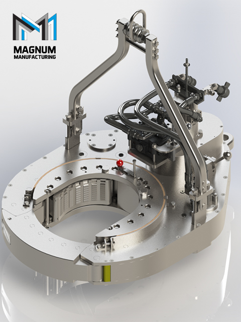
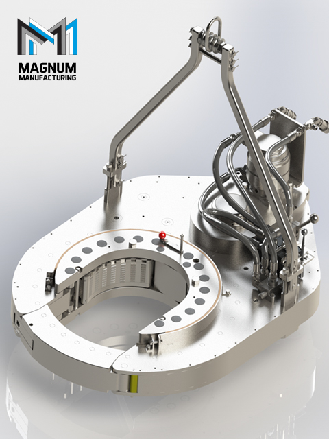
As seen in FIGS. 1 and 2, the power tong 6 may include three main sections mounted on a common axis A; namely a main drive section, a rotor, and a back-up jaw. Each of the sections contains actuators, as better described below. The main drive section 10 which provides at least part of a rigid stationary framework or stator frame is located above the rotor 22. The backup jaw 48, located below rotor 22, may also provide part of the stator frame. The rotor 22 rotates relative to the main drive and back-up jaw. Both the rotor and backup jaw clamp their respective sections of pipe. The rotor 22 is rotated by the main drive section 10 independently of the main drive section and backup jaw in the sense that the rotor 22 is self-contained, having on-board hydraulic and electric power generators to power on-board radial clamps or grippers (collectively herein referred to as grippers), and an on-board serpentine secondary power transmission, all configured to allow the insertion and removal of a pipe through a jaw opening from or into the center of the jaw, so that the pipe, when in the center of the jaw may be clamped, torqued, and spun about axis A of rotation of the rotor 22 while the other, oppositely disposed section of pipe is held clamped in the center of the back-up jaw 48.
As shown in FIGS. 1, 2 and 3 rotor 22 is housed within drive section 10, although this is not intended to be limiting as the rotor may be mounted so as not to be housed within the drive section and still work. The rotor 22 is cylindrical in shape and has an opening slot, which although illustrated as linear may be linear or non-linear, having a throat 38 for passing of a tubular along the slot thereby allowing the tong axis of rotation A to be selectively positioned concentric with pipe 8, provided the rotor 22 is rotated such that its throat 38 is aligned with the front openings 28 and 29 of the main drive section and back-up jaw, respectively. Center 40 of the yoke formed by the jaw and slot corresponds with axis A. The rotary jaw 22 has three gripper cylinders 44 a, 44 b, and 44 carranged radially, with approximately equal angular spacing around axis A, mounted between the two parallel horizontal planes containing rotor gears 30 aand 30 b. The number of gripper actuators, such as gripper cylinders 44 a-44 c, and associated grips or grippers may be more or less in number, so long as a tubular joint may be gripped or clamped at center opening 40.
A serpentine member such as serpentine drive belt 20 is driven by two serpentine drive motors 18, which may for example be hydraulic or electric motors. The serpentine member is mounted around so as to engage stator sprockets mounted on the stator frame. For example the stator sprockets may include drive sprockets 26 awhich are driven by serpentine drive belt 20 to collectively provide a secondary drive powering the grippers on the rotor 22. Drive sprockets 26 arotate serpentine drive belt 20 about idler sprockets 26 mounted to drive section 10. And the serpentine drive belt 20 also engages about rotor sprockets 32 a-32 fmounted on the rotor 22 as better described below. The rotor sprockets 32 aand 32 bmay be two generator drive sprockets. The rotor sprockets 32 cand 32 dmay be two pump drive sprockets. Rotor sprockets 32 eand 32 fmay be two idler sprockets. In the illustrated embodiment, which is not intended to be limiting as other embodiments discussed below would also work, the generator drive sprockets, that is, rotor sprockets 32 aand 32 b, transmit rotary power to generators 34. The pump drive sprockets, that is, rotor sprockets 32 cand 32 d, transmit rotary power to hydraulic pumps 36 by the action of serpentine drive belt 20 engaging the upper groove of rotor sprockets 32 a, 32 b, 32 cand 32 d. A synchronization belt, 28 a, connects the lower portions of the rotor sprockets 32 a-32 f. Thus as the rotor 22 rotates on axis of rotation A, even though serpentine drive belt 20 cannot extend across the throat 38 because such a blockage would restrict selective positioning of the pipe 8 along the slot into the tong, serpentine drive belt 20 wraps in a C-shape around the rotor sprockets 32 a-32 f. Serpentine drive belt 20, driven by drive sprockets 26 a, runs on pulleys 26, and on idler sprockets 26 band 26 cmounted to, so as depend downwardly from, main drive section 10. The extent of the C-shape of serpentine drive belt 20 provides for continual contact between serpentine drive belt 20 and, in this embodiment which is not intended to be limiting, a minimum of three of the rotor sprockets 32 a-32 fas the rotor rotates relative to the main drive section 10. The synchronization belt 28 amounted on the rotor maintains rotation of the individual rotor sprockets as they pass through the serpentine gap 29 seen in FIG. 4, that is, the opening between sprockets 26 band 26 c. Synchronization belt 28 asynchronizes the speed and phase of the rotation of each of the rotor sprockets 32 a-32 fto allow each of them in turn to re-engage the serpentine drive belt 20 after they are rotated across the serpentine gap 29 by the action of the rotor rotating relative to the main drive.
During operation of tong 6 the secondary drive (drive motors 18) and serpentine drive belt 20 run continuously to deliver power to the on-board pumps and generators by means of the rotor sprockets 32 a-32 d. Rotation of the rotor 22 by the operation of the primary drive acting on the pinions 56 and rotor gears 30 aand 30 bdoes not substantially affect the powering of the on-board accessories (pumps and generators) because drive belt 20 is run at substantially an order of magnitude greater speed than the speed of rotation of rotor 22. The rotation of the rotor only adds or subtracts a small amount of speed to the rotation of the rotor sprockets.
Upper rotor gear 30 aand lower rotor gear 30 bare parallel and vertically spaced apart so as to carry therebetween hydraulic pumps 36, generators 34, the rotor hydraulic system, rotor jaw electrical controls and the array of three radially disposed hydraulic gripper cylinders 44 a, 44 b, and 44 c, all of which are mounted between the upper and lower rotor gears 30 aand 30 bfor rotation as part of rotor 22 without the requirement of external power lines or hydraulic lines or the like. Thus all of these actuating accessories, which are not intended to be limiting, may be carried in the rotor 22 and powered via a nested transmission, nested in the sense that the C-shaped synchronization drive loop mounted on the rotor, exemplified by synchronization belt 28 a, is nested within so as to cooperate with the C-shaped serpentine drive loop mounted to the main drive, exemplified by serpentine drive belt 20.
Thus as used herein, a serpentine belt, such as the serpentine belt 20, driving a plurality of stator and rotor sprockets (as herein below defined), and as in the various forms of the stator and rotor sprockets found illustrated in all the figures herein, are herein referred to generically as a form of nested transmission. The nested transmission transfers power from the fixed stage to the rotational stage in a continuous fashion as, sequentially, one element after another of the rotational drive elements on the rotating stage are rotated through and across throat 38 and gap 29 allowing selective access of the tubular 8 to the center opening 40 of the stage.
For proper operation of the tong, it is desirable that the gripper actuators such as gripper cylinders 44 a-44 cclamp the tubular 8 substantially at, that is, at or near the rotational center axis of the tong. It can be readily seen that gripping the tubular 8 with a significant offset from the center axis would result in wobble or runout of the tubular when spinning in or out and could result in thread damage, excessive vibration, damage to the machine and inaccurate torque application.
It will be appreciated that the inboard ends of side gripper cylinders 44 aand 44 bmove in an arc as the gripper cylinders are extended or retracted. For the side gripper cylinders 44 aand 44 b, the geometry of reaction links 44 eis optimized to minimize deviation from the nominal gripper cylinder radial axis over the gripping diameter range to angles typically less than one degree. The gripper cylinders 44 aand 44 bwill however swing significantly from the nominal gripper cylinder radial axis, in the order of five degrees, when they fully retract to clear the throat 38. It is an advantage of the link design that it requires less stroke to clear the throat 38 due to the swing associated with the arc of reaction links 44 e, which ultimately allows a more compact rotor and hence a more compact tong. That is, the combination of the swing in direction C with the retracting stroke in direction D results in less of a stroke length required to clear throat 38 than merely using a retraction stroke without swing. The amount of swing is governed by the radius of arc E associated with rotation of the reaction links 44 eand the length of the required stroke in direction D.
The back-up jaw section 24 as shown in FIGS. 5, 5 a, 6 and 8 is typically mounted to a tong positioning system capable of holding the tong assembly level and enabling vertical and horizontal positioning travel. The tong may be pedestal-mounted on the rig floor, mast-mounted, track-mounted on the rig floor or free hanging from the mast structure. It may also be mounted at an angle for slant drilling application or with the pipe axis horizontal.
In the preferred embodiment, as seen in FIG. 10, the rotor hydraulic system 53 is a dual (high/low) pressure system or infinitely variable pressure system which produces high pressures (in the order of 10,000 psi) necessary for adequately gripping large and heavy-duty tubulars and for applying make-up or break-out torque, and lower pressures (2500 psi or less) to avoid crushing smaller or lighter-duty tubulars. Hydraulic pumps 36, rotationally driven as described above, are fixed-displacement, gear or variable displacement piston pumps. In the idle state, hydraulic pumps 36 charge one or more gas-filled accumulators 55 mounted in or on rotor 22 to store energy to enable rapid extension of the gripper cylinders 44 a-44 c. In this way, very fast gripping speeds may be achieved while keeping the power transmitted by the serpentine drive belt 20 drive low. That is, although the power supplied via the serpentine drive belt is small, the rotor hydraulic system must be able to intermittently supply a relatively large flowrate at low pressure for rapid advance of the gripper cylinders until they contact the tubular and also supply a low flowrate at very high pressure, in the order of 10,000 psi, to adequately grip the tubular for torquing operations.
In the schematic of the preferred rotor hydraulic system 53 of FIG. 10, system 53 has one or two gear or piston pumps 36 of relatively small capacity, within the power limitations of the serpentine drive belt. When there is no gripping demand, the pumps charge one or more gas-filled accumulators 55 to store energy for intermittent peak demands. The accumulators are optional, for the benefit of advance speed. The system is workable without accumulators provided the pumps are variable displacement. A load-sensing circuit with or without regenerative advance may also be used as would be understood by someone skilled in the art. A directional control valve 63 directs hydraulic pressure to the gripper cylinders. The directional control valve is solenoid-actuated with the solenoids controlled by the rotor control system. There are two flow paths from the directional control valve 63 to the extend side of the gripper cylinders. The first is the rapid-advance flow path which directs a large flowrate, in the order of thirty-five gallons per minute, from the pump(s) 36 and accumulator(s) 55 to the gripper cylinders at relatively low pressure, in the order of 2500 psi, for rapid extension of the gripper cylinders until they contact the tubular 8. The second is the high-pressure path in which pressure is regulated by a proportional pressure control valve 64 which is controlled by the rotary jaw control system of FIG. 11. The regulated pressure is supplied to an intensifier 65 which boosts the pressure by a factor in the order of 4:1 to supply high pressure, in the order of 10,000 psi, to the gripper cylinders. A check valve 66 prevents the high pressure fluid from flowing back into the rapid-advance low pressure flow path. The directional control valve 63 can also be solenoid actuated to direct fluid to the rod side of the gripper cylinders for retraction.
The use of high grip pressures, in the order of 10,000 psi, allows the use of compact gripper cylinders which results in a compact tong. By using the intensifier 65 to build the high grip pressure, no high pressure control valves are required.
It can be seen that in spite of the small input power, the hydraulic system can intermittently supply large flowrates for rapid grip cylinder advance and high pressures for high-torque operations. The system can regulate the grip pressure, adapting to the applied torque, for optimum gripping performance.
The rotor control system seen in FIG. 11 activates and de-activates the gripper cylinders at the operator"s discretion, regulates grip pressure and monitors system function without any power supply or control wires from or to the fixed part of the tong, because the rotor is fully rotatable and the open throat of the yoke precludes the use of any slip rings which are commonly used to transmit electrical power and control signals to a rotating element.
As seen in FIG. 11, one or two generators 34 are driven by the serpentine belt drive 20. They supply power, preferably 24 volts DC, to a programmable logic controller (PLC) 70, a radio communication link 71 and a number of sensors 73.
The radio communication link 71, which may advantageously be a Bluetooth™ device, communicates wirelessly with a similar radio communication link 72 mounted on the stationary section of the tong. The two radio communication links, 71 and 72, act as a wireless communication bridge between the main tong control system 74 and the rotor PLC 70.
The rotor PLC 70, as directed by the main tong control PLC 74, controls the output solenoids on directional control valve 63 to extend and retract the gripper cylinders 44 a-44 cand the proportional pressure control valve 64 to control the grip pressure. It also receives feedback from sensors 73 on the rotor for such parameters as (possibly including but not limited to) grip pressure, hydraulic pump pressures, grip position and hydraulic oil temperature.
When breaking out (unscrewing) drilling tubulars, it is often difficult to identify the axial location of the split where the two tool joints meet. It is imperative that the tong be positioned such that the split is located in the axial gap between the rotor grippers and the back-up jaw grippers. If either the rotor or the backup jaw grips across the split, the tool joint and the tong may be damaged and time will be wasted because the connection will not break out.
As shown in FIGS. 15 and 16, the actual face seam 200 between the mating connection shoulder faces 201 is only marginally visible when the connection is made up and it may be further obscured by drilling fluid. There is typically a shoulder bevel 202 adjacent to each shoulder face 201. The shoulder bevel 202 is typically machined at a 45 degree angle and has a radial dimension typically 2 to 6 mm. The two adjoining shoulder bevels 202 combine to form a connection split bevel V-groove 203. The connection split bevel V-groove 203 is usually sufficiently visible to identify the split axial location for placement of manual tongs in conventional drilling operations. But for a mechanized tong with its operator positioned several feet away from the pipe, it may be difficult to see. Furthermore, the tong may obscure the operator"s direct view of the split location. Time will be wasted in identifying the split location, traveling to it and verifying that the split is correctly located in the axial gap between the rotary and back-up jaws.
For automated pipe-handling operations, it is important for the machine to identify and travel to the correct axial location of the split without control intervention by the operator.
It can be seen that a reliable automated system to detect the location of the connection split would improve speed and efficiency of a mechanized tong and is mandatory for fully-automated tong operations.
A tandem configuration may be employed. That is, the optical tubular caliper can be accomplished with a pair of single point beam sensors positioned approximately 180 degrees apart, with each beam projected radially inward toward the tubular at the same elevation. Each sensor measures the radial distance to the pipe surface. The control system computes the sum of these distances. The difference between a fixed offset value and the computed sum represents the diameter of the tubular, approximately independent of the position of the tubular in the opening. The system can quickly and accurately measure the diameter of any tubular passing through the single point beams and transmit the diameter measurement to the tong control system. Furthermore, as the tong travels axially along the pipe, the tong control system can relate a series of such diameter measurements to the corresponding tong elevations as measured via the control system instrumentation described elsewhere. A diameter profile along the length can thus be created, effectively a virtual diameter versus axial position plot. The control system can compare this diameter profile to the known characteristic of the connection split bevel V-groove 203. When such a profile match is identified, the connection split is located and the corresponding tong elevation is recorded. The tong then travels the contact axial offset distance between the light band 705 axial mounting position and the desired split position between the rotary and back-up jaw grippers.
The control system is programmed to tune out irrelevant variations in the measured outside diameter, such as at the tool joint upset steps. It will also filter out diametral noise associated with surface irregularities such as hardbanding, tong marks or wear grooves.
As mentioned above, the power tong according to the present invention may be mounted in many ways on the drilling rig structure, or it may also be free-hanging from a cable. The mounting method ideally allows the tong to be accurately positioned around the tubular 8 at a large range of elevations, retracts a substantial distance from well center for clearance for other well operations, parks in a small area to minimize space usage on the drilling rig floor, keeps the tong level and allows the tong to be positioned to work at multiple locations such as the mousehole which may not be in the same plane as well center and the tong park location. The mounting system could be capable of rapid movement between working and idle positions but with smooth, stable motions. It should allow the operator to command horizontal or vertical movements or a combination.
Numerous tong or wrench mounting mechanisms exist in the industry. Most are Cartesian (horizontal/vertical) manipulators employing tracks, slides or parallelogram linkages for each motion axis. These mechanisms are simple to control because they directly actuate on the horizontal and vertical axes but they typically have a small range of motion which limits tong functionality and restricts mounting location on the drill floor. They have a large parked footprint which consumes scarce rig floor space and interferes with other well operations. And they have little or no capability to react torque applied to the tong or wrench by a top drive in the rig.
Thus in one preferred embodiment, a tong is preferably mounted on a manipulator 99 as shown in FIGS. 12aand 12b. A slewing base 100 is mounted to the drilling rig floor. A hydraulic slewing motor 101, via a gear reduction, can turn the slewing base up to three hundred and sixty degrees about the vertical axis. The internal bearings of the slewing base can support the weight and overturning moments of the manipulator structure and the tong. Slewing motor 101 may alternatively be electric, pneumatic or manually actuated.
The tong is pivotally mounted at the end of boom 103. The angle of the tong relative to boom 103 is controlled by linear actuator(s) 106. The inclination of the tong is monitored by angle sensor 109.
Various possible tong positions are selectively positioned between the extended operating position illustrated in FIG. 12aand the parked position of FIG. 12b. It can be seen that the manipulator 99 provides a large range of motion but can park the tong 6 with a small footprint.
The booms have significant lateral and torsional stiffness. This is advantageous over prior systems because the structure can react torque applied to the tong by a top drive in the rig, such as for back-up of drilling connection make-up. The tong can also apply torque to make up a bit restrained in the rig"s rotary table.
Manipulator 99 may be fully functional with manual controls for each of the four output actuators (slewing motor 101 and linear actuators 104, 105 and 106). However, it preferably has a control system as described below in which horizontal and vertical rates of tong travel are controlled in direct proportion to horizontal and vertical velocity commands by the operator and the tong is automatically kept level. The control system may also include the capability of optimized travel, including acceleration and deceleration control, to pre-defined locations.
The tong"s vertical and radial positions (relative to the slewing base) at any time are computed by the programmable logic control (PLC) 112 geometric constants and the boom 102 and 103 angles measured by angle sensors 107 and 108. The slewing orientation is measured preferably by an encoder 110 on the slewing drive. The tong"s three-dimensional position is therefore monitored at all times.
The preferred operators control console has a single 3-axis joystick 111 for control of the manipulator. The x-axis of joystick 111 controls the horizontal motions of the tong, the y-axis of the joystick 111 controls the vertical motions of the tong and the z-axis (handle twist) of the joystick controls the slewing motions of the assembly. The joystick commands may be discrete ON/OFF but are preferably analog/proportional on the x and y axes for finer control.
Horizontal motion of the tong requires movement of both boom 102 and boom 103, accomplished via linear actuators 104 and 105. The required output velocity signals to each of linear actuators 104 and 105 are computed in the PLC 112 in order to achieve the desired horizontal command velocity from the x-axis of joystick 111.
Similarly, vertical motion of the tong requires movement of both boom 102 and boom 103, accomplished via linear actuators 104 and 105. The required output velocity signals to each of linear actuators 104 and 105 are computed in the PLC 112 in order to achieve the desired vertical command velocity from the y-axis of joystick 111.
The control system may also have capability for automated travel to pre-defined locations such as well center, mousehole and parked position. When the operator commands automated travel to a desired pre-defined target location, the control system control acceleration, travel velocity, deceleration and landing speed for both horizontal and vertical axes to achieve optimum travel to the target, with minimum elapsed time and smooth, controlled motion.
In particular, in FIG. 18, serpentine drive belt 20′ is driven by at least one serpentine drive motor which may for example be at least one hydraulic motor. The serpentine drive motor drives at least one drive sprocket 26 a′ which, as before, provide a secondary drive via a plurality of rotor or satellite sprockets 32′ on rotor 22, and also drives a synchronizer between sprockets 32′ and a coupling such as pumps or generators, or a mechanical mechanism powering gripper actuators and corresponding grippers 44′, or directly acting on grippers 44′, on the rotor 22. As illustrated by way of example, a first drive stator sprocket 26 a′ rotates serpentine drive belt 20′ about a second stator sprocket which may be a second drive sprocket 26 a′ or an idler sprocket 26′ mounted to drive section 10. A tensioner 27 such as a tensioning idler sprocket, which may be considered a third stator sprocket, may be mounted to frame 60 so as to be resiliently biased against serpentine drive belt 20′ to tension the drive belt. A pair of satellite or rotor sprockets 32′ are mounted on the rotor 22. As seen in FIG. 18, the first and second stator sprockets are mounted on substantially opposite sides of the rotor. As the term is used herein, the first and second stator sprockets are arrayed substantially around the rotor. Third, fourth, etc stator sprockets would thus not have to be on one side or the other of the rotor, but would form part of the array of stator sprockets arrayed substantially around the rotor.
The rotor sprockets 32′ drive for example one or more on-board generators and/or one or more on-board hydraulic pumps (not shown in FIGS. 18 and 19). Synchronization belt 28 a′ may connect the lower or upper portions of the rotor sprockets 32′, with the serpentine drive belt 20′ then connecting the upper or lower portions of the rotor sprockets 32′ respectively. Thus as rotor 22 rotates about axis of rotation A even though serpentine drive belt 20′ cannot extend across the opening throat 38 because such a blockage would restrict selective positioning of the pipe 8 along the slot into the tong, serpentine drive belt 20′ wraps around or reaves so as to remain at all times in contact with at least one of rotor sprockets 32′. Drive sprockets 26 a′ are mounted to, so as to for example depend downwardly from, main drive section 10. As seen in FIG. 18a, the deflection of serpentine drive belt 20′ by the rotation of rotor sprockets 32′ provides for continual contact between serpentine drive belt 20′ and a minimum of one of the rotor sprockets as the rotor 22 rotates relative to the main drive section 10, wherein the deflection of serpentine drive belt 20′ tensions the portion of drive belt 20′ where it contacts tensioner 27. Upon return of the rotor sprockets to the position of FIG. 18, tensioner 27 takes up the slack in the drive belt 20′.
As seen in FIG. 19a, rotor 22, the rotor sprockets 32′, and one or more energy coupling 45 may be mounted within a rotary jaw frame 47 on, for example, bushings 49. Energy couplings 45 couple the energy being transmitted from the serpentine to the rotor sprockets 32′, and couples the energy to the grippers 44′ or gripper actuators (which in turn actuate the grippers). As stated above, energy couplings 45 may include pumps, generators, or mechanical drives such as direct mechanical linkages, but may also include the use of energy storage such as, without intending to be limiting, gas accumulators, batteries, capacitors, flywheels, which may then power actuation of the grippers when needed.
A power tong (1) device, in which the power tong (1) includes two housing halves (2), pivotable relative to each other, the housing halves (2) being arranged to be pivoted between a closed, active position and an open, inactive position, and in which a radially divided drive ring (6, 8), which is provided with hydraulically activated clamping dies (14) directed towards the centre axis (10) of the power tong (1), is placed in the housing halves, the drive ring (6, 8) being supported and connected to a driving motor (12) for the rotation of the drive ring (6, 8) about said axis (10), the drive ring (6, 8) being provided with at least one locking means (16) which is arranged to interconnect the parts of the drive ring (6, 8) in a releasable manner.
This invention relates to a power tong. More particularly it relates to a power tong, in which the power tong comprises two housing halves pivotable relative to each other, the housing halves being arranged to be pivoted between a closed, active position and an open, inactive position. A radially divided drive ring provided with hydraulically activated clamping dies directed towards the centre of the power tong is placed in the housing halves, the drive ring being supported and connected to a drive for the rotation of the drive ring about said centre axis. The drive ring is provided with at least one bayonet catch, which is arranged to connect the parts of the drive ring in a releasable manner.
In connection with drilling operations in the ground, in which joinable drill pipes are used, for example in the recovery of petroleum, mechanized pipe tongs in the form of power tongs are well known and extensively used.
Power tongs of this kind normally include hydraulically or mechanically activated grippers or clamping dies which are arranged to clamp a pipe grippingly.
It is common that power tongs either are provided with a radial opening or can be opened, so that the power tong can be moved in a radial direction onto and away from the pipe.
Due to the relatively great clamping forces that are necessary when pipes are being connected, open power tongs are often relatively heavy because they have to be sized to be able to absorb said forces. Closed power tongs, in which the clamping forces can be absorbed by a closed ring, are often relatively light, but it has turned out to be difficult to provide a closing mechanism for the power tong, which is both strong enough and which exhibits the necessary reliability.
A power tong according to the invention includes two housing halves, pivotable relative to each other, the housing halves being arranged, preferably hydraulically, to be pivoted between a closed, active position and an open, inactive position. A radially divided drive ring, which is provided with hydraulically activated clamping dies directed towards the centre axis of the power tong, is placed in the housing halves, the drive ring being supported and connected to at least one driving motor for the rotation of the drive ring about the centre axis. The drive ring is provided with at least one locking means, typically in the form of a bayonet catch which is arranged to join the drive ring together in a releasable manner.
In the drawings the reference numeral 1 denotes a power tong, s which includes two housing halves 2, movable relative to each other and connected, jointly liftable and lowerable, to a support 4 in a manner known per se.
A piston 38 extending in a cylinder 40 in the extension of 2D the piston recess 36, is arranged to move the index pin 32 to its second position, in which the index pin 32 is disengaged from the piston recess 36 and thereby is free to rotate about the centre axis 10 of the power tong together with the drive ring 6, 8.
a radially divided drive ring having a first and a second drive ring part, one or more locking means and a plurality of hydraulically activated clamping dies directed towards a centre axis of said power tong , said drive ring is located in said housing halves, said drive ring being supported and connected to a driving motor for the rotation of said drive ring about said centre axis, said drive ring and said locking means arranged to interconnect said first and second drive ring parts in a releasable manner.
11. The power tong in accordance with claim 10, said bayonet catch comprising a locking body hydraulically rotatable between an active and a non-active position.
12. The power tong in accordance with claim 11, said locking body comprising at least one locking dog, said locking body and said locking dog being located on one of said first and second drive ring parts and fitting complementarily into a recess in the opposite drive ring part, a rotation of said locking body about a centre axis moving said locking dog between the active and the non-active position.
13. The power tong in accordance with claim 12, further comprising said bayonet catch being rotatable by a movable index pin located in said drive ring, said index pin cooperating with an eccentrically mounted pivot on said locking body.
14. The power tong in accordance with claim 13, further comprising said index pin being movable by a corresponding hydraulic cylinder located in one of said housing halves.
15. The power tong in accordance with claim 13, further comprising said bayonet catch being in the inactive position and said index pin being moved into a piston recess in one of said first and second housing halves.
16. The power tong in accordance with claim 10, further comprising said first drive ring part and said second drive ring part each having a radial guide list and said drive ring parts bearing on each other along said radial guide lists, said first and second drive ring parts being arranged to be rotated about said guide lists in order to relieve said bayonet catch.
Magnum Manufacturing is a team of experienced casing running engineers and industry-leading professionals tired of working with existing substandard equipment. We have spent decades developing equipment to the highest industry standards, and we personally have been using the equipment we’ve developed. After 30+ years of partnering with a leading American TRS company to ensure optimal performance, we are prepared to stake our reputation on Performance, Longevity, & Safety.

[0001] The present invention relates generally to making up and breaking out wellbore tubulars and, more particularly, to apparatus and methods for a simplified self-contained power tong for use in a rig floor environment.
[0002] Power tong systems maybe used to spin, makeup, or connect and breakout or disconnect wellbore tubulars that may have a wide range of diameters. Comparison studies between use of traditional separate tongs and spinners as compared with a self-contained power tong system makeup and breakout tool working under similar conditions have shown cost savings that range from one-quarter of a million to more than a million dollars per well, depending on the well conditions.
[0003] Separate, manually operated tongs, spinners, and/or chains are significantly slower and less accurate and consistent in making up and breaking out wellbore tubulars than a single tool or unit that does all such functions. Besides increased speeds of making up and breaking out tubular connections, other time saving advantages of a self-contained power tong unit also include factors such as eliminating the need to redress tongs when changing from drill pipe to drill collars and the integration of spinning with makeup and breakout functions. Due to the high daily cost of drilling rigs, comparison studies show that the time/cost savings can be substantial.
[0004] The self-contained power tong system also operates more reliably than separate tongs and spinners and may provide a central torque regulator that connects to and controls all components to assure consistent makeup. This feature prevents thread damage caused by over-tightening and automatically prevents errors that could result in under-torqued connections. Obviously, a single error, when making up hundreds of threaded connections in a drill string, can result in huge costs of time and material, and even loss of a well.
[0005] The self-contained power tong system also eliminates accident conditions commonly associated with separately moveable independent tongs which apply high torque and which are located by personnel on the floor. As well, independent tongs have attendant separate cables used to pull on each separate tong, and may also use snatch blocks. Thus, the personnel must work between high tension cables that pull on the tongs and accidents can easily occur under such conditions, e.g., if a tong loses its grip and moves rapidly across the rig floor accelerated by the high tension on the cable. Of course, accidents can slow work progress and significantly increase the costs of drilling.
[0006] Safety is also improved because the invention provides a single tool to perform all such functions, rather than separate elements, permits the use of central safety features such as, for instance, a lockout to prevent spinner operation if the tongs are not engaged, a safe location for the operator to stand and work, a design whereby the operator"s hands and feet are safely away from moving parts, elimination of spinning chains, and a lockout to prevent operation of the lift cylinder when any tong is engaged.
[0007] Because of the great utility of prior art self-contained power tong units to makeup and breakout pipes, and the increasingly expanding market for such devices, it has been found highly desirable to make further improvements. It would be highly desirable to simplify the operation of such devices thereby reducing the number of components necessary for operation of the power tong unit. Consequently, there remains a need for an improved self-contained makeup and breakout unit that reduces the complexity and therefore the costs such as manufacturing costs and maintenance thereof. Those skilled in the art have long sought and will appreciate the present invention which addresses these and other problems.
[0008] The present invention was designed to provide more efficient operation to thereby reduce drilling costs, to improve reliability of making and breaking pipe joints, to permit increased automation to reduce required manpower, to improve safety, and to free other rig equipment for other uses.
[0009] Therefore, it is an object of the present invention to provide an improved self-contained power tong unit for making and breaking well bore tubulars.
[0015] Accordingly, the invention comprises, in one embodiment thereof, a power tong system operable for making and breaking joints between wellbore tubulars. The power tong system may comprise one or more elements such as, for instance, a frame, a spinner secured to the frame that is operable for spinning the wellbore tubulars for the making and breaking of the joints, and/or a first member pivotally connected with respect to the frame such that the first member is rotatable with respect to the frame. The first member preferably defines a bore and/or a slot therein for receiving the wellbore tubulars. Other elements may, for instance, comprise a first plurality of gripping members mounted to the first member which are movable inwardly and outwardly for gripping and releasing the wellbore tubulars, and/or a piston/cylinder assembly comprising a piston slidable within a cylinder. The piston/cylinder assembly may be pivotally mounted with respect to the frame and with respect to the first member such that the first member is rotatable with respect to the frame in response to movement of the piston with respect to the cylinder. Additional elements may comprise a second member mounted to the frame also defining a slot therein for receiving the wellbore tubulars and a second plurality of gripping members mounted to the second member. The second plurality of gripping members may also be movable inwardly and outwardly for gripping and releasing the wellbore tubulars. The power tong system may further comprise a control arm mounted to the first member, the control arm may be moveable between a first position and a second position, the first member may be rotatable for tightening the wellbore joints in the first position, the first member may be rotatable for loosening the wellbore joints in the second position. Other elements may comprise a fastener for selectively securing the control arm in the first position or the second position. In one embodiment, the fastener further comprises a pin, latch, or other fastening means.
[0016] The power tong system may further comprise a pivotal connection between the control arm and the first member and/or a pivotal connection between the control arm and the piston/cylinder assembly.
[0018] A method for a power tong system for making and breaking joints between wellbore tubulars are provided that may comprise one or more steps such as, for instance, mounting a plurality of gripping members to a rotatable member, providing that the gripping members are moveable inwardly toward the tubulars for gripping the wellbore tubulars and moveable outwardly away from the tubulars for releasing the wellbore tubulars, pivotally mounting a control to the rotatable member, connecting a piston/cylinder assembly which may comprise a piston and a cylinder, to the control arm such that the rotatable member rotates in response to movement of the piston with respect to the cylinder, providing that the control arm is moveable between a first position and a second position, providing that when the control arm is in the first position, then the member is operable for applying torque to the wellbore tubulars for making the joints, and/or providing that when the control arm is in the second position, then the member is operable for applying torque to the wellbore tubulars for breaking the joints.
[0022] In yet another embodiment, the power tong system may comprise, a frame, a first member pivotally connected with respect to the frame such that the first member is rotatable with respect to the frame, a first gripping assembly mounted to the first member for gripping and releasing the wellbore tubulars, a second member mounted to the frame, a second gripping assembly mounted to the second member for gripping and releasing the wellbore tubulars, lift members attached to the frame for moving the first member and the second member upwardly and downwardly to align the first member and the second member with respect to the joints, a joint connection detector operable for detecting joint connector components for producing a joint signal to indicate the joint connection components wherein the joint connection detector may be in a clearance position with respect to the joint connection components, and an automatic control for receiving the joint connector. The automatic control may be operable for operating the lift members to automatically align the first gripping assembly and the second gripping assembly with respect to the joints.
[0028] FIG. 1 is an elevational view, partially in phantom lines, showing a tong in a first position and selectively rotatable in a first direction in accord with one embodiment of the invention;
[0029] FIG. 2 is an elevational view, partially in phantom lines, showing the tong of FIG. 1 in a second position after rotation in the first direction in accord with one embodiment of the invention;
[0030] FIG. 3 is an elevational view, partially in phantom lines, showing the tong of FIG. 1 in a first position and selectively rotatable in a second direction in accord with one embodiment of the invention;
[0031] FIG. 4 is an elevational view, partially in phantom lines, showing the tong of FIG. 3 in a second position after rotation is the second direction in accord with one embodiment of the invention;
[0035] Referring now to the drawings and more particularly to FIG. 1, there is shown a preferred embodiment of rotatable tong 12 for applying torque to tubular connections. In FIG. 5 there is shown one possible embodiment of self-contained power tong system 10 in accord with the present invention utilizing one or more rotatable tongs 12 for applying torque to tubular connections.
[0036] Rotatable tong 12 may be utilized as an upper tong or a lower tong and may also be used for both an upper tong and a lower tong which operate in conjunction with each other by rotating in opposite directions. In the embodiment shown in FIG. 5, upper rotatable tong 12 operates in conjunction with a lower fixed position lower tong 14. Thus, upper tong 12 rotates and applies torque to upper pipe 16 while lower tong 14 acts as a back-up tong for holding lower pipe 18 in a fixed position. While in a preferred embodiment, lower tong 14 does not rotate, lower tong 14 could also be designed to rotate in an opposite direction with respect to upper tong 12, thereby doubling the degree of potential rotation available per operation for application of torque to joint 20. Upper tong 12 and lower tong 14 effectively provide sturdy upper and lower members which also support gripping members, as discussed below, in a suitable manner for applying high forces to the joint connections.
[0037] In a preferred embodiment, spinner 22 is utilized to quickly spin or rotate upper pipe 16 with respect to lower pipe 18 which is held in position by lower tong 14 until the joint is almost made up. Spinners are well known in the prior art and spinner 22 may utilize a known spinner design, if desired. While spinner 22 is capable of spinning pipe quickly until the threaded connection is almost made up thereby reducing the time required per joint, spinner 22 typically does not have sufficient power to apply the necessary torque required to complete the make-up for most tubular joints. Therefore, it is desirable to utilize spinner 22 in conjunction with a tong set capable of applying the necessary torque, as might be required per pipe manufacturer"s recommendations.
[0038] While upper tong 12 rotates only a relatively few degrees, as suggested in the different positions of upper tong 12 between FIG. 1 and FIG. 2, the upper tong 12 rotates with ample high-torque to complete the joint make-up according to the drill pipe manufacturers" specifications or any other standards.
[0039] FIG. 1, FIG. 2, FIG. 3, and FIG. 4 show, in some detail, the salient characteristics an embodiment of rotatable tong 12 of the present invention during various stages of operation, including rotation effectively in two different directions to thereby permit the same tong set to be utilized for both making-up and breaking-out pipe joint connections. Depending on the location of pin 24 in hole 26 or in hole 28, rotatable tong 12 may be made to effectively rotate in opposite directions for selectively tightening (making-up) or loosening (breaking-out) tubular joints, as discussed in more detail hereinafter.
[0040] In FIG. 1, rotatable tong 12 may comprise a circular member 30 with a circular outer perimeter 32. However, rotatable tong 12 may also be shaped differently around its perimeter. In any case, member 30 is built to have sufficient structural integrity to apply the necessary torque. Rotatable member 30 may comprise layers, support beams, housings to cover the elements shown in the drawings, and the like as desired, to provide the necessary structural integrity to apply the necessary torque.
[0041] Member 30 of rotatable tong 12 maybe mounted for rotation around rotation center point 34. Member 30 may be supported by suitable bearings as indicated at 37 in FIG. 5 between preferably telescoping and/or preferably moveable structural support members 38. Alternatively or in addition, suitable bearings may be provided for mounting to tong frame 36 (not shown). The bearings for mounting member 30, such as bearings 37 and/or other bearings, must be sufficiently strong to support the various forces acting thereof while torque is applied while constraining member 30 to rotate about center point 34.
[0042] In a preferred embodiment, rotatable tong 12 rotates in response to force produced by piston/cylinder assembly 40. Piston/cylinder assembly 40 actuates reciprocal movement of piston rod 42 with respect to cylinder housing 44. Piston/cylinder assembly 40 may be hydraulically or pneumatically actuated, as desired.
[0043] FIG. 1 shows rotatable tong 12 in the starting position prior to rotation with piston rod 42 extended with respect to cylinder housing 44. In the starting position slot or throat 62 is oriented to permit the pipe to move into or out of power tong system 10 prior to or subsequent to performing an operation involving applying torque to the pipe joint. FIG. 2 shows rotatable tong 12 in an ending position just after the joint has been operated upon with piston rod 42 retracted with respect to cylinder housing 44. The ending position may typically be in the range of thirty to one hundred degrees of rotation from the starting position. Movement arrows 46 and 48 in FIG. 1 show that rotational movement in the direction indicated by arrow 48 is associated with extension movement of piston rod 42 with respect to cylinder housing 44 as indicated by directional movement arrow 46. In this top view, extension of piston rod 42 results in counterclockwise rotational direction of member 30.
[0046] FIG. 3 and FIG. 4, as compared to FIG. 1 and FIG. 2, show the effect of removing pin 24 from hole 26 of member 30, pivoting control arm 58 until mating hole 60 in control arm 58 is aligned to hole 28, and inserting pin 24 therein. Pin 24 may be held in place by clips, latches, cotter pins, and so forth. With pin 24 mounted through hole 28 of member 30 and hole 60 of control arm 58, rotatable tong 12 may be made to effectively turn in the opposite direction from the starting position as shown in FIG. 1 and FIG. 2. In this case, as shown in FIG. 3, piston rod 42 is in a retracted position with respect to piston/cylinder assembly 40 when slot 62 is in the starting position. Piston rod 42 moves in the direction indicated by arrow 43, then member 30 rotates as indicated at 45, and piston/cylinder assembly rotates as indicated at 47.
[0047] Then as shown in FIG. 4, member 30 rotates counterclockwise from the starting position as indicated by arrow 64 as piston rod 42 extends in the direction of arrow 66 with respect to piston/cylinder assembly 40. Piston/cylinder housing rotates counterclockwise as indicated by arrow 68 and as discussed hereinbefore. To return to the opening position, piston rod 42 is contracted or moved as indicated by arrow 43 in FIG. 3 toward piston/cylinder housing 40. Corresponding to movement of piston rod 42 in the direction of arrow 43, member 30 of rotatable tong 12 rotates clockwise as indicated by arrow 45 and piston/cylinder housing 40 also rotates clockwise as indicated by arrow 47.
[0048] In a preferred embodiment, as best shown by numbers noted in FIG. 3, three gripping assemblies 80, 82, and 84 are utilized to grip the pipe within upper rotatable tong 12 and/or lower fixed position tong 14. The gripping assemblies of both upper tong 12 and lower tong 14 may be substantially similar, if desired. Gripping assemblies 80-84 may be substantially similar, and may operate similarly, if desired. Alternatively, one or more of the gripping assemblies may be substantially different and operate differently, if desired. Gripping assemblies 80-84 may be manually operated, hydraulically operated, or pneumatically operated, or some combination thereof. In a preferred embodiment, gripping assembly 82 is utilized as a guide member and may preferably be affixable in a desired selectable position that is determined by the size of pipe to be operated upon by tong system 10. Once fixed in the desired position, bite die 86 of gripping assembly 82 does not move but is affixed in position to thereby act as a guide to position the pipe in the correct position when the pipe is inserted into opening 62. On the other hand, gripping assemblies 80 and 84 move respective bite dies 88 and 90 radially inwardly and outwardly to thereby grip the pipe and/or release the pipe, as required. Rod 100, which may or may not be piston activated, or threadably activated, may be moveable for moving bite die 86 to the desired position. Adjustment member 102 may be utilized to select and affix piston rod 100 in the desired position either manually or automatically. Adjustment member 102 may have latches, thread connections, or the like to thereby affix and securely hold bite die 86 in the desired selected position.
[0051] Referring to FIG. 5, various means maybe provided to move system 10 into position for operation such as a moveable member, boom, cables, wheels, rails and the like for which base 116 may be adapted. System 10 may be moved into position for each joint, or may simply remain in a single position while building in or removing the pipe string. Mounts 118 may be used to lift system 10 upwardly or downwardly as required to position upper tong 12 and lower tong 14 in the desired vertical position with respect to the pipe. The mounts maybe hydraulically or pneumatically moveable, such as with pistons, as desired. Mounts 38, which may also be hydraulically or pneumatically moveable, may also be expandable/contractible to control the spacing between upper tong 12 and lower tong 14.
[0052] Slips 117 may be utilized to grip pipe 18 to support the pipe string, as desired. Slips 117 may be automatic slips, if desired. In one embodiment, slips 117 may comprise sender/receiver sensor/actuator 119 for sending receiving commands and status information about the slips, e.g., slips open or slips closed. Thus item 119 may comprise one or more or all components operable to provide an electronic sender, or electronic receiver, or electronic sensor, or an actuator. Sender/receiver/sensor/actuator 119 may be wireless or cable connected. Various types of sensors maybe utilized. For instance, pipe inspection device 120 and/or 122 maybe utilized to magnetically and/or electromagnetically inspect the pipe for defects when running the pipe into the wellbore or removing it therefrom. If desired, the pipe inspection results may also be utilized to detect the position of joint 20 and/or the tops or bottom of pipe 16 and 18. Once the position is known, then the system may automatically adjust its position to the pipe. Thus, pipe inspection device may comprise an electric coil, acoustic signal sender, magnetic flux detector, or other means for detecting discontinuities. The same components may also be used for detecting joint components such as the pin or box end of the joint as well as joints that are made up. The pipe inspection device and/or collar locator are mounted in a clearance position with respect to the pipe and do not require contact with the pipe to operate. If desired, the collar locator, if used, may be a separate component and spaced apart from the pipe inspection device. Moreover, more than one pipe inspection device or collar locator could be used for more complete inspection and/or faster location of collars to thereby more quickly move upper tong 12 and lower tong 14 into position.
[0053] In another embodiment, suitably located cameras, such as cameras 124, 126, and/or 128, maybe utilized, along with suitable lighting, to provide the driller or system 10 operator, a clear view of the position of the pipe joint. Thus, in FIG. 6, the position of the pipe and/or the position of system 10 and/or upper tong 12 and/or lower tong 14 may be seen in monitor 132 and compared with reference lines 130 for exact positioning. The optical system may be manually operated by the drill utilizing monitor 132 and/or other displays and controlling the equipment, such as system 10 height controls and/or the pipe handling equipment such as the blocks, slips, and the like.
[0054] Alternatively, the shapes of pipe connections are easily recognizable with an optical recognition system, for example in FIG. 6, that may be controlled by controller or computer 134. Optical recognition may be faster and, for example in FIG. 6, more reliable for locating the relative position of upper tong 12 and lower tong 14 with respect to a particular part of the joint which can be quickly recognized, e.g., the top outline of the socket or bottom outline of the pin, or when the pipes are connected then the profile of the connected joint. Thus, the optical system may comprise an optical collar locator that may be used to adjust the relative heights of upper tong 12 and lower tong 14. Moreover, the system may be used for inspecting the wellbore tubulars when the wellbore tubulars are clean and dry, as maybe provided whe


 8613371530291