
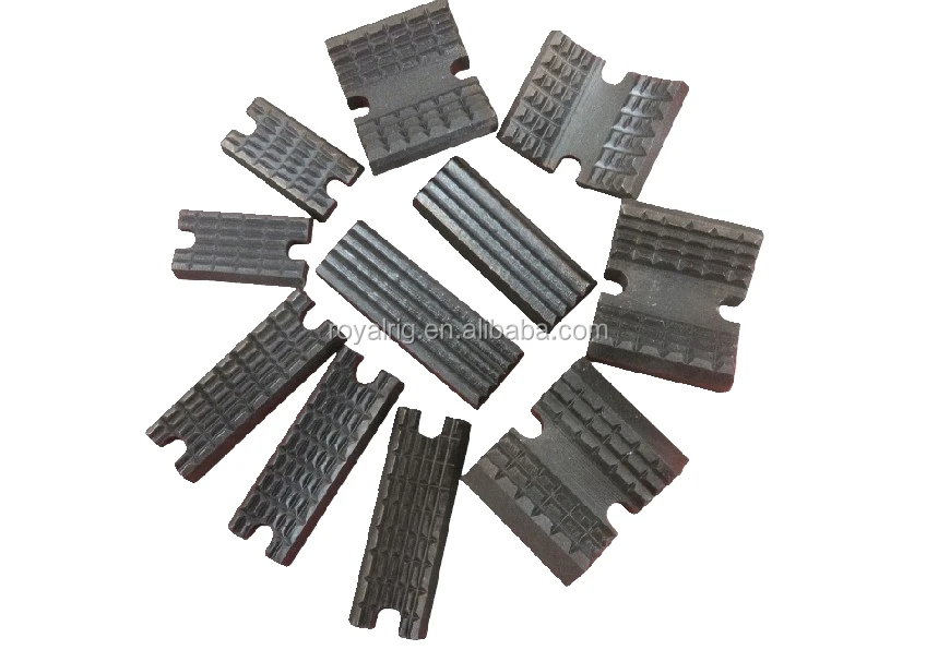
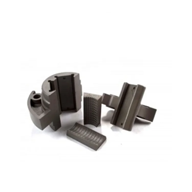
drill pipe power tong dies in stock

When buying a power tong dies, you can also minimize your production costs in the future by standardizing some elements of the mold. This means that if you have multiple molded products, you can ask for standard lift bars, connection sizes and clamp slots across all your molds to make them easy to use.
Our huge network of mold shops on Alibaba.com are ready to help you find the right wholesale power tong dies for your products. Use the information available on the platform to decide on the perfect power pu dies that meet your requirements of quality and price. When starting a molded products manufacturing project, it starts with a dfm or design for manufacturing which is created by the mold making shop after analyzing your product design and is there to tell you how the mold is going to be made. After your approval, the mold will be made according to the mold shape.
If you are looking for distinct categories of power tong dies, Alibaba.com is the best place where you can find loads of them. These sturdy and optimum quality power tong dies are ideal for making a vast array of items ranging from normal household products and appliances to automotive and other commercial products too. These power tong dies are fully customizable and professional OEM products that are the best fit for any type of manufacturing plant. Buy these from the leading suppliers and wholesalers on the site. The plastic injection power tong dies available on the site are of export quality and they are made from sturdy materials such as plastic, metal, ABS, PE, PMMA, PC, POM, PBT, PP, PA66, PPO, PVC, PET, etc that are well known for their robust structures. The best part of using these power tong dies is the precision it offers while sh.

Tong dies have come a long way since tongs became commonplace in the oilfields. Eckel has been at the forefront of this developing technology with the development of larger wrap-around type dies for many of its tong models. We offer coarse tooth design and fine tooth design depending on the application.
Rig Dies (Typically 1" and 1-1/4" wide) are available in coarse tooth die are typically used for casing and drill pipe where tool joint O.D. sizes vary from joint to joint. Also, Drill Pipe is also a harder steel and rig dies provide a more aggressive and better grip. Rig dies are available with the following surface areas:
Coated Contour True Grit® Dies: Used on chrome and fiberglass tubulars where reduced die penetration and die marking is greatly desired. For more information refer to the

Tong dies have come a long way since tongs became commonplace in the oilfields. Eckel has been at the forefront of this developing technology with the development of larger wrap-around type dies for many of its tong models. We offer coarse tooth design and fine tooth design depending on the application.
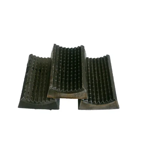
Wrap-Around Dies are considered the best choice for thinner wall tubulars where point loading is a concern. Wrap-Around Dies are symmetrically spaced from each other at all times insuring an equally distributed load on the tubular. Having a larger gripping surface area allows more teeth to come in contact with the tubular. Wrap-Around Dies come in any size to match tubing and casing tubulars and API coupling diameters. Wrap-Around dies are available with the following surface areas:
Coated True Grit® Dies: Used on chrome and fiberglass tubulars where reduced die penetration and die marking is greatly. For more information see the True Grit® Dies section.
Eckel offers contour type dies for tubing sizes on many of our tongs which use pivot heads. In addition to our contour dies, we provide A and S series wrap-around dies for our 13-3/8 and 20 Standard casing tongs, providing a larger gripping area and reducing pipe damage. Rig type dies are used extensively for 4-inches and above. Sliding heads with rig dies is the best choice when running drill pipe connections.
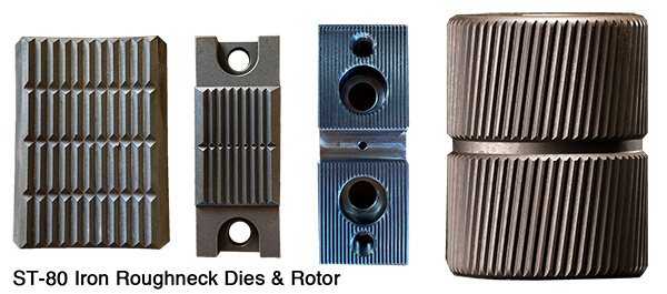
World Petroleum Supply stocks a full line of inserts and dies which include: elevator inserts for all Slip Type Elevators; slip inserts for drill collar, rotary, and casing slips; tubing and drill pipe tong dies; and coil tubing inserts for elevators, slips, and spiders. We also manufacture tong dies for the ST-80 Iron Roughneck.
Our manufacturers make dies and inserts from quality materials and precision machine them to exacting tolerances. They are heat-treated to industry standards to provide the best wear and resistance for the harshest of environments.
Offshore Energy Services, Inc. (OES) Tubing Division has a complete inventory of Tubing and Drill Pipe Tongs for use in chrome and carbon steel applications.

- DIES FOR PIPE AND TUBING TONGS Filed April 18. 1960 4 Sheets-Sheet 1 CROSS CUT DEPTH TOOTH DEPTH i n N a 3 Q 4 L- I 2 M 4 it m E 8 I o PEI-I 21 m m; E 1 Q :0;
u.| l 5* I 5 i" l M 4 l 4 INVENTORS 0.5. MARQUIS 8 J.H. PROVINCE N n v: -n o l o m 2 I I J BY z ,w% r I 7 ATTORNEYS March 1964 D. E. MARQUIS ETAL 3 3 DIES FOR PIPE AND TUBING TONGS Filed April 18. 1960 4 Sheets-Sheet 2 x (PENETRATION CROSS SECTION) INVENTORS D. E. MARQUIS J.H. PROVINCE A 7" TORNEKY March 10, 1964 D. E. MARQUIS E" I"AL 3,
DIES FOR PIPE AND TUBING TONGS 4 Sheets-Sheet 4 Filed April 18. 1960 INVENTORS D.E. MARQUIS J.H. PROVINCE A T TORNEVS United States Patent 3,124,023 DIES FOR PIPE AND TUBING TONGS Duane E. Marquis and John H. Province, Bartlesville,
0kla., assignors to Phillips Petroleum Company, a corporation of Deiaware Filed Apr. 18, 1960, Ser. No. 22,842 19 tllaims. (Cl. 81186) This invention relates to a die for pipe and tubing tongs. In one aspect this invention relates to an improved die which, when employed in pipe and tubing tongs, causes less damage to the pipe or tubing being made up or broken out with the aid of said tongs. In another aspect this invention relates to an improved die for pipe and tubing tongs which die provides maximum contacting surface of essentially the same curvature as the outer circumference of the pipe or tubing to which said die is applied.
Thus, it has been found that much of the handling damage is caused by the dies in the tongs employed in making up and breaking out joints of tubing. As a result of extensive field, laboratory, and experimental tests we have invented a new die for pipe and tubing tongs, which die reduces damage to said pipe or tubing to the minimum, but yet provides efiicient safe handling in making up and breaking out strings of pipe or tubing.
An object of this invention is to provide an improved die for pipe and tubing tongs. Another object of this invention is to provide an improved die for pipe and tubing tongs which provides maximum tooth contacting areas and minimum tooth penetration, thereby resulting in the elimination or mitigation of tong die damage. Another object of this invention is to provide an improved die which is less subject to clogging. Still another object of this invention is to provide an improved die which is easier to clean. Another object is to provide an improved power tong adapted to be employed with said die. Other aspects, objects and advantages of the invention will be apparent to those skilled in the art in view of this disclosure.
Thus, according to the invention there is provided a die for pipe and tubing tongs, said die comprising: a bar-like body having a concave working face provided with a plurality of buttressed teeth thereon; said teeth having a substantially triangular cross section and being arranged in from 5 to 9 spaced apart parallel rows per inch of said concave working face; each of said teeth having an apex length or contacting surface within the range of to 4 inch; said teeth being spaced apart in said rows a distance within the range of from A to inch; and said apexes of said teeth providing an arcuate contacting surface having a curvature essentially the same as the outer circum ference of the pipe or tubing with which said die is to be employed.
We have found said combination of factors or elements to be essential in reducing die damage to the minimum. The concave working face provides the curved foundation necessary for realization of maximum advantage from the other elements of the combination. The buttress type teeth of substantially triangular cross section provide maximum tooth strength which is highly desirable when employing maximum applied torque. Said buttress type teeth also provide a better initial bite which is particularly desirable when working with dirty or scaly tubing. The specified spacing of the rows of teeth, the specified tooth apex or contacting length, and the specified spacing of said teeth in said rows all cooperate to provide an interrupted marking pattern. Said interrupted marking pattern is essential in order to avoid a continuous or elongated marking pattern which causes a concentration of immediate damage and sets up a concentration of stress forces which lead to future failures. The arcuate contacting surface of essentially the same curvature as the curvature of the outer circumference of the pipe or tubing with which the die is to be employed spreads the applied forces over the maximum area and insures that each tooth will bear its share of said applied forces and reduces individual tooth penetration to the minimum.
Each of said elements is critical to the combination, within the above specified limits, in that each cooperates with the others to provide a unitary end result, i.e., a die, which when employed in a pipe or tubing tong and applied to a pipe or tubing, will cause minimum damage to said pipe or tubing.
As used herein and in the claims, unless otherwise specified, the expression arcuate contacting surface having a curvature essentially the same as the outer circumference of the pipe or tubing with which said die is to be employed refers to the curved surface presented by the apexes or contacting surfaces of the die teeth. Said contacting surface is of course an interrupted surface. The curvature of said surface can be further defined in terms of radius of curvature. For example, consider a nominal two inch tubing having an outside diameter of 2.375 inches plus or minus 0.031 inch, the usual tolerance to which such tubing is manufactured. The radius of curvature of the outer wall of said tubing is 2.375/ 2 or 1.1875 inches, which would be the radius of curvature R (see FIGURE of the arcuate contacting surface provided by the tooth apexes or contacting surfaces of a die fabricated in accordance with the invention and intended to be employed with a tubing or pipe having an outside diameter of 2.375 inches.
FIGURE 4 is a diagrammatic view, partly in cross section, illustrating a conventional tubing power tong which has been modified to employ the dies of the invention.
FIGURE 5 is an enlargement of the gripping mechanism of the power tongs of FIGURE 4 and illustrates the relationship between the teeth of the die of the invention and the circumference of a pipe or tubing.
Referring now to said drawings the invention will be more fully explained. In said drawings like reference numerals are employed to designate like elements. FIG- URES 1, 2 and 3 illustrate one presently preferred specific embodiment of a die in accordance with the invention and which is particularly adapted to be employed with a nominal 2 inch tubing having an actual outside diameter of about 2.375 inches Said die comprises a bar-like body 20 having concave working face 21 provided with a plurality of buttressed teeth 22 superimposed thereon. Said teeth have a substantially triangular cross section, and in the particular embodiment illustrated are arranged in 11 parallel rows spaced apart about inch. Each of said teeth has an apex or contacting surface 23 (sometimes referred to as tooth length) of about inch. Said teeth are spaced apart in said rows a distance of about /8 inch at their apexes to provide about 17.5 inches of total lineal contacting surface. Thus, said 11 rows of teeth provide a contacting surface consisting of 187 points of contact. Said contacting surface provided by said teeth apexes or contacting surfaces is an arcuate contacting surface having a curvature essentially the same as the outer circumference of the pipe and tubing with which said die is intended to be employed, in this specific embodiment a 2% inches O.D. tubing. In FIGURE 1 the vertical numbers 1 to 11 designate row numbers.
In the specific embodiment illustrated, each of said teeth 22 has an apex angle of about 72 degrees. As employed herein and in the claims, unless otherwise specified, the term apex angle refers to the angle included by the apex and the faces of the tooth. The tooth depth is about 0.090 inch and the tooth cross cut depth is about 0.060 inch. It is to be noted that said tooth cross cut depth is less than the tooth depth. This is an important feature of the dies of the invention. The smaller cross cut depth renders the die largely self-cleaning because materials which tend to accumulate between the teeth, both transversely and longitudinally, accumulate in a wafile-like pattern wherein one dimension is less than the other, is consequently less stable, and more apt to not adhere to the die.
In the specific embodiment illustrated the back face 24 of the die is slightly convex and the side faces 26 are tapered. The amount of curvature on said convex back is not critical so long as it is not large enough to cause instability. In the die illustrated said curvature is about equal to the curvature of a circle having a radius of 12 inches. If desired, said back face 24 can be fiat. Said tapered sides are tapered at an angle of about 15 degrees. Said tapered sides are advantageous in holding the dies of the invention in the grooves provided in the bushing and jaw of the tongs. Said convex back is provided to enable or provide a slight rocking motion within said grooves when the dies are first brought into contact with the pipe or tubing and thus aid in fitting or placing the die to the tubing or pipe with which it is to be employed. Opening 25 is provided for convenience in stringing the dies for temporary storage as when a string or wire is passed through a set of dies to keep them separate from other similar dies. The specific embodiment of the die of the invention illustrated in FIGURES 1, 2 and 3 has an overall length of 3 /8 inches and a width at the base of 2 inches.
Referring now to FIGURE 4, there is illustrated a conventional power tong which has been modified to accommodate the dies of the invention. Said power tong is of the general type illustrated in US. Patent 2,618,467 issued to C. A. Lundeen on November 8, 1952. Said power tong comprises a bushing 27 and a jaw 28 which are part of an inner ring assembly 29 which is actuated by an outer ring assembly 31. Said bushing 27 is provided with two adjacent tapered grooves 34 and 36 which contain dies A and B fabricated in accordance with the invention. Said dies are held in place in said bushing and said jaw by means of cotter pins 35 at the top and bottom (not shown). The sides of said tapered grooves 34 and 36 are tapered at approximately the same angle as the side faces of said dies A and B but said grooves are slightly wider than said dies A and B so as to provide room for said dies A and B to rock on their convex back faces in said grooves when said jaw 28, containing die J, is brought into contact with a tubing (not shown). Said bushing 27 is stationary in said inner ring assembly 29 while said jaw 28 is hinged at the point 32 so that as said outer ring assembly 31 rotates in the direction indicated by the arrow with respect to said inner ring assembly, the roller 33 will roll along the cam surface of said jaw 28 and cause die I to be moved into contact with a tubing or pipe (not shown). Power tongs of the general type here illustrated are well known to those skilled in the art and no further explanation of their operation is believed necessary. Further details concerning the operation of power tongs of this general type can be found in said Patent 2,618,468.
FIGURE 5 illustrates more clearly the relationship between the dies A, B, and I, fabricated in accordance with the invention, and a tubing which has been placed in the power tongs and jaw 28 closed. It will be noted that the contacting surface provided by the teeth of each of said dies A, B and J covers an area of the tubing equivalent to about 70 degrees of the circumference of said tubing, or a total area of 210 degrees for three of said dies. In the practice of the invention it is preferred that each die cover an area of the tubing which it contacts equivalent to at least about 60 degrees of the circumference of said tubing. This feature of the invention, i.e., the apexes of the teeth of said dies providing an arcuate contacting surface having a curvature essentially the same as the outer circumference of the pipe or tubing with which said dies are employed, provides an important advantage of the invention.
Referring to said Patent 2,618,468 it will be noted that each of the dies 93, 94, and 95 has a maximum contact surface of only about 20 degrees on the surface of the pipe or tubing. Said dies 93, 94 and 05 in FIGURES 5 and 6 of said Patent 2,618,468 are conventional flat face dies provided with four teeth running the entire length of the die. Due to the flat faces of said standard die and the curvature of the tubing, only one of said teeth and perhaps a trace of a second tooth makes contact with the tubing. Since each die is approximately 3% inches long, this results in a total of only about 17 lineal inches of contact, all concentrated in three or more continuous die marks. This concentration of the die marks is highly undesirable, particularly with the new type tubings, due to the stress patterns developed.
The invention is of course not limited to the die having the specific dimensions or the specific tooth marking patterns discussed above in connection with the drawings. For example, in another embodiment of the invention, illustrated in FIGURES 7 and 8, the die is essentially the same as that discussed above except that said second embodiment die is provided with only 9 rows of teeth having 153 points of contact providing 14.34 lineal inches of contact on each die, or a total of 459 points of contact amounting to a total of 43.03 lineal inches of contact when three dies are employed in combination. The teeth in this embodiment of the invention have an apex angle of about 68 degrees. This last mentioned embodiment of the die of the invention allows for wider spacing (about inch) between the rows of teeth which improves the self-cleaning features of the dies of the invention. Said last disclosed embodiment of the invention is thus preferred when working with dirty or scaly tubing.
The improved die of the invention is most advantageously employed in connection with the smaller sizes of high pressure tubing, such as nominal 2, 2 /2 and 3 inch tubings, having outside diameters of 2.375, 2.875 and 3.5 inches respectively, fabricated from the new alloys discussed above and which are therefore most subject to handling damage. However, said dies can also be employed with great advantage when making up larger sizes of pipe and tubing, e.g., up to and including nominal 7 inch pipe or tubing, and larger.
It is within the scope of the invention to provide dies having a concave working face provided with a plurality of buttressed teeth superimposed thereon and arranged in from 9 to 13 parallel rows which are spaced from about 0.12 to about 0.18 inch apart. In such dies the tooth length, distance between the teeth in each row, and cross cut depth would be essentially the same as for the above discussed embodiments. The apexes of the teeth in said dies would also provide an arcuate contacting surface having a curvature essentially the same as the outer circumference of the tubing or pipe with which they are to be employed.
Stated another way, the improved dies of the invention can be fabricated with the buttress type teeth arranged in from 5 to 9 spaced apart parallel rows per inch of concave working face. Each of said buttress type teeth would have an apex angle within the range of about 45 to 90 degrees, preferably within the range of 65 to 75 degrees. The apex angle of the teeth will vary with the other dimensions, e.g., number of rows of teeth. Each of said teethwould have an apex length or contacting surface 23 within the range of about to inch. Each of said teeth would have a longitudinal depth within the range of 0.01 to 0.1 inch and a cross cut depth within the range of 0.03 to 0.07 inch. Said teeth would be spaced apart in said rows a distance within the range of about to about 4 inch. The apexes of said teeth, as in the previously described emlbodiments, would provide an arcuate contacting surface having a curvature essentially the same as the outer circumference of the pipe or tubing with whcih the die is to be employed.
We have found, in general, that dies having a total penetration cross section within the range of 0.12 to 0.19 square inches and a tooth length within the range of A to 4 inch, are satisfactory. Using said penetration cross section as a guide, a great number of tests, both in the laboratory and in the field, were run using both conventional standard product dies available from various die manufacturers and special dies made according to special specifications. These test dies included various tooth styles, patterns, and sizes, such as symmetrical, buttress and circular styles, pyramid, coarse and standard long tooth, fiat and curved contacting surfaces, and flat and curved back surfaces. Dies having a flat working face were eliminated early in favor of dies having a concave working face. While it appeared that a buttress type tooth was preferred so as to obtain better initial bite and minimum slip, it was found that with all other factors being substantially the same, said buttress type teeth caused more penetration than could be tolerated. However, it was unexpectedly found that when the individual tooth contacting area was increased, the penetration of the buttress type tooth was decreased without sacrificing any appreciable amount of its superior bite and minimum slip properties.
EXAMPLE I A large number of dies having various tooth types and arrangements were tried in the field under actual operating conditions on tubing installed in operating wells. The objective of these tests was to determine the type of die which caused the minimum amount of die damage; and to determine ways and means for holding tooth penetration to a maximum of 10 mils (0.010 inch), preferably 6 mils if possible, when employing up to 6000" ft.-lbs. maximum applied torque.
The candidate dies were installed in a conventional power tong similar to that illustrated in FIGURE 4 herein and that illustrated in said Patent 2,618,468. The bushing and jaw of said power tongs were modified where necessary to accommodate the candidate dies.
From these tests all dies having a straight working face and all dies having tooth types other than (1) buttress type and (2) symmetrical type, were eliminated. The test results given in Table I below on five different dies are representative of the tests on dies having said two types of teeth.
Table I Penetration Cross Section (X)square inches Applied Die Description of Die Tubing Torque, Bushing Dies Total Xr No. Type 2 it. lhs. .Taw Die, Die A+ Die I, Die B,
1 While number of rows of teeth per die varied, the dies were built with a radius of curvature about 64 inch greater than the nominal radius of the outer wall of the tubing. As a result only an average of about 4 rows of teeth per die contacted the tubing for the 1% inches dies and about 3 rows for the 1 inch dies.
The data given in the above Table I show that the total penetration cross section (X for dies 1, 3, and 5 having symmetrical type teeth were much less than for dies 2 and 4 having buttress type teeth. These data show that a die having symmetrical type teeth develops less penetration cross section for the same applied torque than does a die having buttress type teeth. Thus, from the standpoint of penetration cross section, a die having symmetrical type teeth would be preferred.
The test data also showed that when considered from the standpoint of penetration alone, the dies having symmetrical type teeth would be preferred to dies having buttress type teeth because of the smaller penetration.
Table 11 Average Tooth Penetrationmils Die No. Tooth Type Bushing Dies J aw Die, Die I Die A Die B 1 Symmetrical 9. 2 6. 4 4. 3 2 Buttress. 13 S. 0 12. 3 3 Symmetrical. 9 5. 5 6 4 Buttress l5. 2 24 15. 5 5 Symmetrical 3.5 3 2.5
XJ=XA+XB X =X since XT=XJ+XA+XB 7 X r 7 X AJ= 2"T and AA=AB="TT" Thus, the data showed that when employing dies having symmetrical type teeth, the jaw die I does about /2 the work whereas the bushing dies A and B each do about A the work.
Thus, the data showed that when employing dies having buttress type teeth, all three dies A, B and I do about the same amount of work. From this standpoint the dies having buttress type teeth are preferred.
EXAMPLE II On the basis of observations during the tests described in the above Example I three dies having symmetrical type teeth and meeting the above determined total penetration cross section requirement of 0.0886 sq. in. for dies having symmetrical type teeth were fabricated. It was desired to reduce the average tooth penetration to 3 mils (0.003 inch) if possible. In order to fit into the power tongs being employed the overall dimensions of each die were set at a length of 3% inches and a width of 2 inches. A tooth contact length of inch with inch space between the teeth in the row was chosen. For a die 3% inches in length this will permit 30 teeth per row or a total contact area of 0.936 inches per row of teeth.
Since the total penetration cross section of 0.0886 sq. in. for dies with symmetrical type teeth is to be met, and since the above distribution analysis showed the jaw die I does /2 the work when the dies have symmetrical type teeth, then Three dies were fabricated with 16 rows of 30 teeth each with the rows being spaced about inch apart. Said teeth were superimposed on a concave working face with the apexcs of the teeth providing an arcuate con- 9 tacting surface having a curvature essentially the same as the outer circumference of a 2.875 inch O.D. tubing.
Said dies were then heat treated to impart a Rockwell C hardness of 61-63 to the teeth surfaces. When tested in a power tong on 2.875 inch O.D. tubings made of 4340 steel and tubings made of 9 chrome steel having Rockwell C hardnesses in the range of 25 to 32, and employing from 2500 to 5000 ft. lbs. of applied torque, the dies slipped and the die teeth acted much in the manner of a cutting tool.
These dies had the proper amount of total contacting surface and met the penetration cross section requirements. However, the individual tooth contacting length (apex length) was not enough to support the penetrated metal and the die slipped.
EXAMPLE III On the basis of observations during the tests described in the above Example I three dies having buttressed type teeth and meeting the above determined total penetration cross section requirement of 0.1595 sq. in. for dies having buttress type teeth were fabricated. The average tooth penetration was set at 3 mils (0.003 inch), die length at 3% inches, and die width at 2 inches for the same reasons as in Example II. A tooth contact length of inch with 4 inch space between the teeth in the row was chosen. For a die 3% inches in length this will permit 17 teeth per row or a total Contact area of 0.1591 inches per row.
Since the total penetration cross section of 0.1595 sq. inch. for buttress type teeth is to be met, and since the above distribution analysis showed that all three dies A, B, and J do about equal work when the dies have buttress type teeth, then (115935 =53.2 lineal inches Total contact= all 3 dies) Number of contact rows= Number of contact rows per die= g =lll Three dies were fabricated with 11 rows of 17 teeth each with the rows being spaced about inch apart. Said teeth were superimposed on a concave working face with the apexes of the teeth providing an arcuate contacting surface having a curvature essentially the same as the outer circumference of a 2.375 inch 0. D. tubing.
Said dies were then heat treated to impart a Rock well C. hardness of 60-61 to the teeth surfaces. When tested in a power tong on 2.375 inch O.D. tubings made of 4340 steel and tubings made of 9 chrome steel having Rockwell C hardnesses ranging from 25 to 32, and employing from 2500 to 5000 ft. lbs. of applied torque, the action of the dies was satisfactory in every respect.
As will be realized by those skilled in the art in view of this disclosure, variations in the outside diameter of the pipe or tubing with which the dies of the invention are employed will affect the performance of said dies. However, due to the general high standard of products produced by American manufacturers of pipe and tubing, said variations are, in general, very small. For example, the API specifications for such products provide that tubings having an outside diameter of 4" and smaller, tolerance permitted in said outside diameter is plus or minus 0.031 inch. Tubing manufactured by American manufacturers is nearly always well within this tolerance. It will also be realized by those skilled in the art that variations in the hardness, e.g., Rockwell C, of the pipe or tubing will also affect the performance of said dies. It is believed clear that the teeth faces of said dies should have a hardness greater than the hardness of the pipe or tubing with which said dies are to be employed.
1. A die for pipe and tubing tongs, said die compris ing: a bar-like body having a concave working face provided with a plurality of buttressed teeth thereon; said teeth having a substantially triangular cross section and being arranged in from 5 to 9 spaced apart parallel rows per inch of said concave working face; each of said teeth having an apex length within the range of from to inch; said teeth being spaced apart in said rows a distance within the range of from to 4 inch; and said apexes of said teeth providing an arcuate contacting surface having a curvature essentially the same as the outer circumference of the pipe or tubing with which said die is to be employed.
2. A die for pipe and tubing tongs, said die comprising: a bar-like body having a concave working face provided with a plurality of buttressed teeth thereon; said teeth being arranged in from 5 to 9 spaced apart parallel rows per inch of said concave working face; each of said teeth having an apex angle within the range of 45 to degrees, an apex length within the range of to inch, a longitudinal depth Within the range of 0.01 to 0.1 inch, and a cross cut depth within the range of 0.03 to 0.07 inch, with one of said dimensions for said longitudinal depth and said cross-cut depth being less than the other said demension; said teeth being spaced apart in said rows a distance within the range of to A1. inch; and said apexes of said teeth providing an arcuate contacting surface having a curvature essentially the same as the outer circumference of the pipe or tubing with which said die is to be employed.
5. A die for pipe and tubing tongs, said die comprising: a bar-like body having a concave working face provided with a plurality of buttressed teeth thereon; said teeth being arranged in from 8 to 12 parallel rows spaced from 0.12 to 0.18 inch apart; each tooth having an apex length within the range of from to inch; said teeth being spaced apart in said rows a distance within the range of from to 4 inch to provide from 12 to 20 inches total lineal contacting surface and said apexes of said teeth providing an arcuate contacting surface having a curvature essentially the same as the outer circumference of the pipe or tubing with which said die is to be employed.
GRITFACE® coating for tong dies and handling tool inserts is the choice of energy service companies around the world. Economical and proven to work, this innovative coating gives you the following benefits:Protects tubulars with minimal marking—the typical indention depth is 0.004″ to 0.006″, less than half of API allowable surface defect depth
McCoy’s standard is used by several premium pipe manufacturers. We define 4.5% of wall thickness as a maximum allowable surface indentation for normal tubular gripping applications. The greatest indention depth documented in testing to date is 3.54%, with typical depths ranging from 1.45% to 2.9%.
GRITFACE® coating for tong dies and handling tool inserts is field-proven to last longer than hardened steel dies and inserts used with high-strength tubulars:Used to run most CRA tubulars in North Sea since 1997 and now used worldwide
Over 155 GRITFACE® inserts are available for almost every handling tool and safety clamp, eliminating the need for specially adapted equipment and increasing the utilization of your handling tool inventory. In the field, our dies and inserts reduce operator fatigue and keep operators safe because they aren’t reaching into tools at each connection. Try GRITFACE® Coating for dies and inserts today.
Smart Solutions & Powerful Products stocked by Oil Nation Inc. We understand what you need. And you need it. Now! Oil Nation has the dies & inserts, oilfield handling tools, in-stock solutions for your business.

DrillingParts.com is in no way affiliated with the companies referenced in this website. References and/or mention of company names or the accompanying computer code are for ID purposes only and are not Trade Marks or Trade Names used by or affiliated with DrillingParts.com. Although under affiliate program agreements, DrillingParts.com may earn on qualifying purchases completed through third party associates such as Amazon, eBay and our marketplace vendors.
Our specialties include new and used oilfield handling tools, new BOPs, tong dies, drill pipe and drill collar elevators, tubing elevators, slip inserts, power tongs, slips and bowls, rubber products including ram rubbers, door seals, BIW rubbers, etc. We also provide replacement parts for all types of handling tools, tongs, and elevators. We can rebuild and recertify all types of elevators.

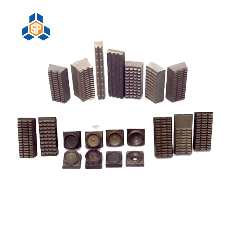
Pan Industries manufactures all sizes and types of Tong Dies. Custom applications are always welcome at Pan Industries. Share any Reference part number, Dimensions, Photo, Drawing and get a instant quote.


 8613371530291