
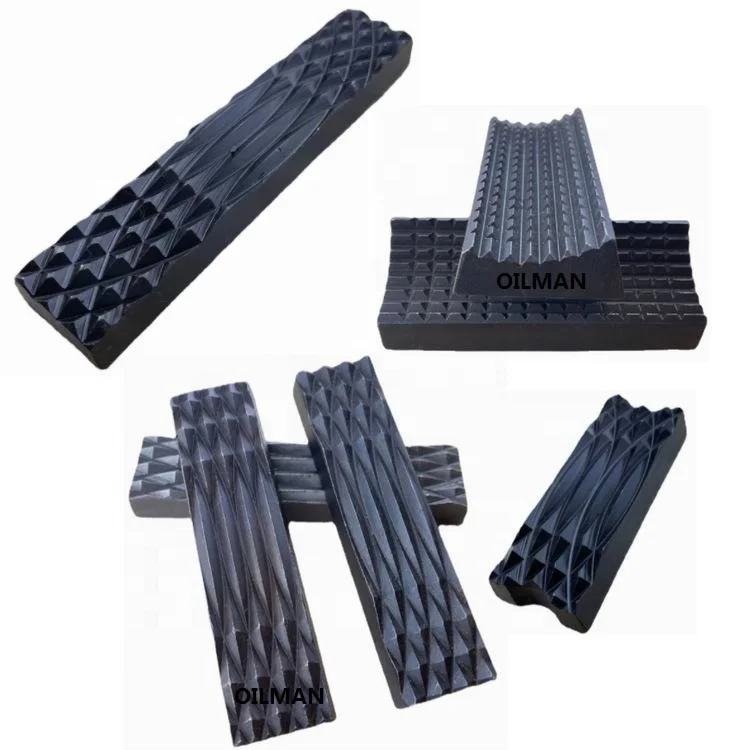
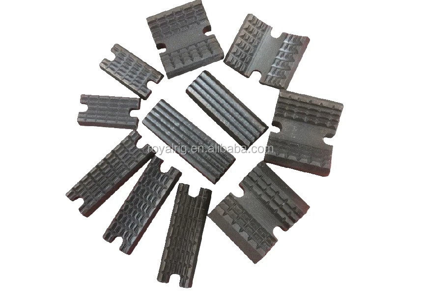
drill pipe power tong dies free sample

This invention is directed to apparatus and methods for aligning wellbore tubulars; and to power tongs used in making and breaking joints of tubular members such as wellbore casing and tubing; to parts thereof; including, but not limited to gripping elements, and methods of their use.
During the drilling of oil and gas wells and the production of materials therefrom, various operations require the connection and disconnection of successive lengths of threaded tubulars such as pipe, casing, or tubing. Tools known as tongs are used to "make" and "break" such connections. Certain known power tongs have a body, a rotary rotatably mounted in said body and at least one active jaw which, on rotation of the rotary is cammed against a pipe in the rotary and grips it for rotation with the rotary. In known arrangements the camming action is generated by a cam member which is bolted to the rotary and is shaped so that the active jaw is cammed against the pipe on rotation of the rotary relative to the active jaw in one sense and will be released on rotation of the rotary relative to the active jaw in the opposite sense.
With known tongs high torques are applied to tubulars due to combinations of factors such as thread sealing requirements, the presence of corrosion, the existence of distortion, and pipe size and weight. Both in the "make" direction of rotation when a shoulder is suddenly encountered, and in the "break" direction at initial engagement of the tong and disengagement of the threads high shock forces may arise; e.g., with a power-driven tong, in excess of 50,000 foot-pounds of torque may be exerted, while relatively small die elements on jaws of the tong engage the pipe with extremely high force loadings. Slippage occurs and pipe surfaces become marred, marked, indented, or otherwise damaged.
Dies for gripping jaws have been provided with multiple serrations, or penetration features, to provide the interference contact at the joint surface. Grip element penetration into the joint surface is limited and controlled. The distribution and balance of grip element energizing forces are critical factors in the design, development and evaluation of such tong mechanisms. Linkages, levers, wedges, and cams are used to balance force components. Grip elements, or dies, are accurately disposed within carrier bodies, or jaws, which span a circumferential segment of the joint surface.
Uneven die loading can cause excessive indentation, marring or damage to a tubular surface. Drag or braking devices are used in certain tongs to effect proper biting of the dies relative to the pipe. The head or other member supporting the dies is frictionally restrained to insure that the dies do not simply rotate with the rotary as the rotary is driven.
Other tongs use an endless belt, chain or flexible material loop for gripping a tubular. Such tongs are disclosed in U.S. Pat. Nos. 3,799,010; 3,906,820; 3,892,140; 4,079,640; 4,099,479; and 4,212,212. There are a variety of problems associated with certain of these tongs:
Jaw/die tongs and the belt/chain tongs are used with relatively hard and rigid metal tubulars such as casing and tubing. If these tongs are used with thick tubulars or tubulars made from relatively "softer" metals or from premium metals such as high alloy steels or low carbon steels or tubulars made from non-metal materials such as fiber glass, they often literally chew up the tubular. The use of strap wrenches is inadequate since the torque applied with such wrenches cannot be precisely controlled.
Certain tubulars are treated with a rust or corrosion resistant material or coating. If the coating is indented, gouged, or broken, its protective purpose is defeated. Producing enough force in a tong to join such tubulars while not injuring a protective coating presents a dilemma.
The present invention, in certain embodiments, discloses a power tong for joining tubulars so that marking of, indentation of, and surface injury to tubulars are reduced or eliminated. In one aspect a power tong is provided and a method of its use for handling tubulars coated with a corrosion-resistant material which should not be broken or penetrated. In one embodiment such a tong has one or more gripping jaws with gripping elements made of aluminum alloys, zinc, zinc alloys, aluminum, brass, bronze, cermet, plastic, fiberglass, metal alloys, or a combination thereof which present a smooth face (straight or curved) to a tubular without any teeth, pointed projections, or toothed dies. In one aspect the gripping elements are releasably connected directly to jaws. In another aspect the gripping elements are releasably connected to a jacket or holder which itself is releasably connected to a jaw.
In order to effectively grip a tubular with gripping elements without teeth, points, or projections so that slippage is prevented, a larger normal force between the jaw and the tubular is needed to maintain gripping-element pipe contact. Pre-loading of jaws with one or more of these gripping elements is achieved, in certain embodiments of this invention, with a pre-load cylinder connected between a fixed gripping jaw and a movable gripping jaw. The cylinder applies a continuous pre-load force on the movable jaw which is not concentrated enough to injure the tubular but is large enough to develop sufficient friction to prevent slippage. In one aspect the force applied by the cylinder is controllable and is adjustable as desired. In one aspect two pre-load cylinders are used, each connected to a different fixed jaw and one at each end of a movable jaw, so that no cylinder movement is required to change modes, e.g. from make-up to breakout. In one aspect one cylinder is used which can be switched from one end of a movable jaw to the other to switch modes of operation.
In one aspect the cylinder(s) are powered by a small air-driven hydraulic pump with an hydraulic fluid reservoir mounted on a plate on the movable or fixed jaw. Air is supplied to activate a motor of the pump and the pump then provides hydraulic fluid to move a piston of the hydraulic cylinder(s). The motion of the cylinder moves the movable jaw on its roller to travel to a pre-load position on the cam. The cylinder applies pressure until the hydraulic pressure is released. A hydraulic fluid accumulator and a valve may be used to maintain hydraulic pressure at all times so that the cylinder(s) continuously maintain the desired load on the jaw until the air supply to the pump is removed.
In another aspect the cylinders are connected to a rotary of the tong or to any other member that rotates with the rotary rather than to a fixed jaw. Such a pre-load system may, according to this invention, be used with any tong including a tong that does use toothed dies.
In one embodiment the present invention discloses a gripping arrangement for a tong with a sheet of grit which is preferably bonded to a carrier plate. In another embodiment the gripping arrangement comprises a layer of flexible material having a smooth flat surface or a surface with ridges and valleys, for example in the fashion of the surface of a file. The flexible material, in one aspect, is metal, for example sheet aluminum, zinc, brass, bronze, zinc alloy, aluminum alloy, stainless steel, or steel having a thickness of about 1.5 mm. The layer of flexible material may be used in conjunction with a carrier plate or on its own. In a further embodiment the gripping arrangement may comprise a layer of perforate material one of both surfaces of which are preferably coated with grit to facilitate adhesion. The layer will typically be formed from metal having a thickness of about 1.5 mm. The layer may be used in conjunction with a carrier plate or used on its own. In yet another embodiment the gripping arrangement may comprise a layer of expanded mesh, e.g. metal mesh, which has been flattened. One or both surfaces of the expanded mesh may be coated with grit and the layer may be used in conjunction with a carrier plate or used on its own. The grit may comprise, for example, diamond dust, particles of silicon, zircon, tungsten carbide and mixtures thereof. The gripping arrangement may comprise end plates which are attached to the carrier plate. Preferably, the carrier plate is provided with side flanges for insertion into a jaw holder. The present invention also provides a jaw assembly fitted with a gripping arrangement in accordance with the present invention. Preferably, the jaw assembly includes a jaw holder having an arcuate recess which accommodates an arcuate pad of resilient elastomeric material which supports said gripping arrangement. Advantageously, at least one shim is provided which is disposed between said arcuate pad of resilient elastomeric material and said gripping arrangement. The shim will be flexible and generally from 0.5 mm to 1.0 mm thick and made from sheet metal. The present invention also provides a tong fitted with at least two such jaw.
In one embodiment the present invention discloses an apparatus for aligning tubulars and includes a guide on one of a power tong and a backup tong. In one embodiment the apparatus has a socket centralizer mounted on said one of said power tong and said backup tong. In one aspect, said one of said power tong and said backup tong is said power tong. In another embodiment, the apparatus includes a power tong and a backup tong, and the guide is mounted on the power tong and apparatus is provided to maintain the power tong and the backup tong in a certain juxtaposition during a stabbing operation. Preferably, said apparatus includes locating rods on one of the power tong and the backup tong and blocks shaped to receive at least the ends of the locating rods on the other of the power tong and the backup tong. Advantageously, the backup tong is provided with at least two prismatic jaw assemblies to locate the backup tong in fixed juxtaposition with respect to a tubular being gripped.
The present invention, in one aspect, provides a jaw unit for use in a tong, which jaw unit comprises a jaw holder and a jaw movable with respect to said jaw holder, characterized in that said jaw is slidably mounted on said jaw holder. Preferably, said jaw is slidable with respect to said jaw holder about an arcuate path. Advantageously, said jaw has a gripping surface which is substantially arcuate for gripping the surface of a tubular and the center of curvature of such arcuate path lies between the center of curvature of said grip ping surface and said arcuate path. The gripping surface may be a continuous surface or defined by several spaced apart gripping elements. Preferably, the center of curvature of said arcuate path lies between the center of curvature of said grip ping surface and said gripping surface. Advantageously, the center of curvature of said arcuate path is substantially midway between the center of curvature of said gripping surface and said gripping surface. Preferably, one of said jaw and said jaw holder is provided with an arcuate track which defines said arcuate path, and the other of said jaw and said jaw holder is slidably mounted in said arcuate track.
The present invention also provides a jaw assembly comprising two jaw units in accordance with the present invention. Preferably, said jaw units are mounted for pivotal movement about a common pivot shaft. Advantageously, said jaw assembly includes means which bias said jaw units apart. The present invention also provides a rotary fitted with a jaw unit in accordance with the present invention, a rotary fitted with a jaw assembly in accordance with the present invention, and a tong fitted with a rotary in accordance with the present invention.
One of the features of existing tongs is that their rotaries are difficult to furnish. Thus, routine maintenance usually involves dismantling the whole rotary, checking the parts and reassembling the whole. While this is a straightforward procedure in the clean conditions of a workshop it can be problematic when carried out in a muddy field, in sand or in snow. The present invention aims to help solve this problem and provides a rotary which comprises a top section, a bottom section, and a peripheral wall therebetween, characterized in that at least one of said top section and said bottom section is provided with an elongate slot which, when said rotary is in use, accommodates a pivot shaft on which a jaw assembly can be pivotally mounted.
Jaw holders and jaws for tongs are traditionally machined from a solid piece. This is a comparatively expensive procedure. The present invention proposes to make such parts from a stack of individually cut laminations.
Such methods and devices including a power tong with at least one jaw with at least one tubular gripping element having a smooth gripping surface (flat or curved) and, in one aspect, such an element which is flexible;
FIG. 2A is a perspective view of a tubular connection system according to the present invention. FIGS. 2B and 2C are perspective views of a casing tong of the system of FIG. 2A.
FIG. 5A shows schematically an initial position of elements of a tong system according to the present invention. FIG. 5B shows pre-loading on a pipe of the jaws of the system of FIG. 5A. FIG. 5C shows a tubular gripped with the system of FIG. 5A.
FIGS. 1A-1C show a typical prior art power tong that uses fixed jaws and a movable jaw to grip pipe for tubular disconnecting and connecting operations. An outer case houses a powered rotary to which the jaws are mounted. A cam surface of the rotary moves a movable (ACTIVE or MASTER) jaw into (and away from) gripping contact with a tubular, e.g. pipe. Each jaw has toothed gripping inserts to facilitate engagement with the surface of the tubular (see FIG. 1B). FIG. 1C shows the tong in an "OPEN" position in which the tubular is not gripped.
The tong shown in FIG. 1A is a Weatherford Model 14.5-50 High Torque Tong. The brochure "New ! Weatherford Model 14.5-50 High Torque Tong," (1991) and the manual entitled "Model 14.5-50 Hydraulic Power Tong Installation, Operation and Maintenance" (1993) are submitted herewith and incorporated herein fully by reference for all purposes. It is to be understood that the teachings of the present invention are applicable to any tong and any tong system that has one or more gripping elements or jaws and that the Model 14.5-50 tong is shown here for illustrative purposes and not by way of limitation of the scope of the present invention.
As shown in FIG. 2A a system 10 according to the present invention includes a power tong 100 according to the present invention which is like the tong of FIG. 1A but which also includes a unique jaw system 110 with inserts 150 on fixed jaws 120 and insert 152 on movable jaw 122 and at least one jaw pre-load assembly like that shown in FIG. 5A. The system 10 includes a free floating backup tong 12.
As shown in FIGS. 2B and 2C, rods 112 are connected to the movable jaw 122. The inserts 150 are on fixed jaws 120 and the insert 152 is on a movable jaw 122 (corresponding to the fixed jaws and active jaw, respectively, of the tong of FIG. 1A).
FIGS. 4A-4G illustrate an alternative jaw mounting system in which holders are interposed between jaw bodies and inserts. The holders protect the jaws from damage if the inserts wear down and a variety of different types and/or sizes of inserts may be used with and interchanged on a single holder. In one aspect it is within the scope of this invention to use these holders to mount conventional toothed dies to a tong jaw and to use them for easy substitution of new and/or different dies.
FIG. 4A shows a jaw system 400 for a tong (like the tong of FIG. 2A) which has two fixed jaws 402 and a movable (movable toward and away from a tubular to be gripped 403) jaw 404. Each jaw 402 has a jaw body 405 with a holder 406 secured thereto. In one aspect dovetail keys 407 secured to the holder or releasably mounted thereto fit in corresponding slots 408 of the jaw bodies 405 to releasably mount the holder 406 to the body. In one aspect dovetail keys 409 releasably mount the holders 406 to jaw bodies 405. The dovetail keys 409 are releasably held in corresponding recesses 411 in the holders 406. One or more dovetail keys 409 may be used (two shown for each holder 406).
FIG. 5A shows a tong system 500 with a tong having a movable rotary 502, fixed jaws 504, 505, and a movable jaw 506 (remainder of tong, not shown, like the tong of FIG. 2A; like the tong of FIG. 1A, but with the added features discussed here). Pins 520 pin the fixed jaws to the rotary. Inserts 522 on the fixed jaws 504, 505 are like the inserts described herein for other fixed jaws. Insert 524 on the movable jaw 506 is like other inserts described herein for movable jaws. A pre-load cylinder 508 to assist in make-up is pivotably connected at one end to the fixed jaw 505 and at the other end to the movable jaw 506. A pre-load cylinder 510 to assist in break-out is pivotably connected at one end to the fixed jaw 504 and at the other end to the movable jaw 506. It is within the scope of this invention for the ends of cylinders connected to the fixed jaws to instead be secured to the rotary or to a support ring or other member that rotates with the rotary. It is within the scope of this invention to employ one cylinder interchangeable between the positions of the cylinders 508 and 510 (FIG. 5A) or one cylinder connectible to the fixed jaw 506 at one end for break-out and at the other end of the fixed jaw 506 for make-up with the other cylinder end secured to the rotary. Rollers 530 rotatably mounted on the movable jaw 506 co-act with cam surfaces 532 on the rotary 502 to move the jaw 506 to operative and inoperative positions.
Air in a line 640 selectively applied with a control system 650 (e.g. mounted on the rig floor, on the tong or remote controlled) selectively actuates the pump 630 to pump fluid through the valve 602 to the pre-load cylinders. The directional control valve 602 is either manually operated or operated by remote control. Correct fluid pressure is monitored with a gauge 651.
As shown in FIG. 5C the tubular 650 has been gripped due to the action of the pre-load cylinder 510 with a suitable pre-load force (e.g., but not limited to, about 500, 1000, 5000, 10000 or 50000 pounds of force). This force is sufficient that when the rotary 502 of the tong is rotated the jaws do not slip on the tubular 650; but the pre-load force is sufficiently low that the jaws do not mark or damage the tubular 650.
FIG. 8 shows schematically a top view of a power tong according to the present invention. A power tong T has an hydraulic motor M with control/monitor apparatus C on a tong case S. A movable jaw J is moved and rotated by a rotary R which is moved by interconnection, via appropriate gearing, by the motor M. Fixed jaws F and G are secured to the rotary R. A first pre-load cylinder D connects the movable jaw J to the fixed jaw G for applying a pre-load to the movable jaw for make-up operations. A second pre-load cylinder L connects the movable jaw J to the fixed jaw F for applying a pre-load to the movable jaw for break-out operations. An insert I (any insert disclosed herein) is secured to the movable jaw J and inserts K (any insert disclosed herein) are secured to the fixed jaws F and G.
FIG. 9 shows a tong jaw 450 according to the present invention with an insert 454 (any insert disclosed herein) and rods 452 secured thereto, e.g. by welding. The rods 452 provide a member to which either a cylinder body or a piston of a pre-load piston cylinder apparatus is connectible. Instead of the rods 452 as shown which extend from above the jaw 450 to a point below it, only rod sections may be used secured to one or both sides of the jaw to provide a securement member for an end of a pre-load apparatus.
According to the present invention a variety of apparatuses and devices may be employed to pre-load a tong jaw having one or more smooth faced gripping insert elements thereon. In one aspect a manually activated pre-load cylinder is used which has fluid or material manually introduced therein to apply a pre-load or manually removed therefrom to release a pre-load. In another aspect a pre-load cylinder is pivotably secured at one end to a rotary or part thereof and the other end is releasably connectible to either end of a movable jaw so that a pre-load may be applied, selectively, to either end of the movable jaw for make-up or break-out operations as desired. In one aspect such a pre-load cylinder has a rod with an end member receivable in and movable in a slot in the movable jaw or there are recesses at either end of the jaw for holding the end member of the rod so that a pre-load can be applied. A secondary small cylinder may be used to selectively move the pre-load cylinder in the jaw slot or it can be moved manually. In another embodiment the tong"s movable jaw has one or more upwardly projecting lugs engageable by a forked piston rod end of a pre-load piston/cylinder that is attached to the rotary. The rotary is rotated so that the jaw is cammed into the pipe to be rotated in a pre-load position and then the forked rod is removed for further tong operations.
In use, two or more jaw assemblies are placed in a tong and are disposed around a length of casing. The jaw assemblies 1001, 1001" are then advanced radially inwardly in the direction of arrows "A" (FIG. 12) until they engage and firmly grip the casing. Because of the flexible construction of the gripping arrangement 1007, the shims 1006 and the arcuate pad 1004, the friction layer 1009 substantially conforms to the circumference of the casing and grips the casing with a substantially uniform gripping action. Once the casing has been firmly gripped the jaws are rotated by the tong in the usual manner. It will be noted that circumferential forces applied to the friction layer are transmitted through the carrier plate 1008 so that any local loads caused, for example by an irregularity in the surface of the casing are redistributed by the carrier plate 1008 and transmitted to the jaw holder 1002 via the side flange 1011 and the arcuate pad 1004 (see FIG. 18).
The present invention is useful for gripping casing for rotation. Gripping arrangements in accordance with the present invention may also be used for gripping and rotating other tubulars, for example tubing or drill strings, or for use in slips, for example for supporting a casing string or drill string while lengths are being added thereto or subtracted therefrom.
Referring to FIGS. 19A and 19B of the drawings there is shown a conventional tong assembly which is generally identified by the reference numeral 2001.
The power tong 2002 comprises a pair of gates 2004, 2005 which are held together in the position shown by latch 2006. When the latch 2006 is released the gates 2004, 2005 can be swung open by admitting hydraulic fluid to piston and cylinder assemblies 2007 and 2008. The power tong 2002 also contains a rotary 2009 which is provided with four jaw assemblies 2010. The rotary 2009 can be rotated by a hydraulic motor 2011.
The backup tong 2003 is provided with two gates 2012, 2013 which are held together by latch 2014 but which, when latch 2014 is released can be swung to an open position.
Once the pin is correctly located the stabbing guide is removed. The gates 2004, 2005 of the power tong 2002 and the gates 2012, 2013 of the backup tong 3 are then opened and the tong assembly 2001 moved towards the casing until the lower length of casing lies within the backup tong 2003 and the upper length of casing lies within the power tong 2002. The gates 2004, 2005, 2012, 2013 are then closed and latched. Jaw assemblies in the backup tong are then advanced to engage the lower length of casing while jaw assemblies in the power tong 2002 are advanced to grip the upper length of casing. The hydraulic motor 2011 is then actuated to turn the rotary 2009 and rotate the upper length of casing relative to the lower length of casing. The tong assembly 2001 is supported by a pneumatic lifting cylinder 2015 which enables the power tong 2002 to move towards the backup tong 2003 as the pin enters the socket. Reaction forces are transmitted by columns 2016 disposed to either side of the tong assembly 2001 and by a series of levers in a known manner. It should be noted that the power tong 2002 is free to move in a plane parallel to the backup tong 2003 within certain limits.
The apparatus 2100 comprises a tong assembly 2101 which is generally similar to the tong assembly 2001 shown in FIGS. 19A and 19B and parts of the tong assembly 2101 similar to the tong assembly 2001 have been identified by similar reference numerals in the "2100" series.
Turning first to the guide 2117 it will be seen from FIG. 21B that this comprises four identical components 2118 which are bolted to the top of the power tong 2102. As best shown in FIG. 21C each component is tapered so as to guide the pin of an upper casing to the center of the opening of the power tong 2102.
Referring now to FIG. 22, the backup tong 2103 is provided with three prismatic jaw assemblies 2119a, 2119b, and 2119c which, when actuated, hold a lower length of casing 2120 in a fixed position relative to the backup tong 2103.
As shown in FIG. 23 the backup tong 2103 is provided with three upwardly extending locating rods 2121 which are each provided with a conical tip 2122. Similar, the underside of the power tong 2102 is provided with three blocks 2123 each of which is provided with a recess 2124 shaped to receive the conical tip 2122 of a respective locating rod 2121.
In use, the lower length of casing 2120 is first secured by slips on the rig floor in the usual manner. The gates 2112 and 2113 of the backup tong 2103 are then opened and the tong assembly 2101 moved into position with the backup tong 2103 circumjacent the lower length of casing 2120 and immediately below the socket 2125 thereof.
The gates 2112 and 2113 are then closed by hydraulic piston and cylinder assemblies 2126 and 2127 and the latch 2114 closed. The prismatic jaw assembly 2119a is fixed while prismatic jaw assemblies 2119b and 2119c are automatically advanced by a predetermined distance when the latch 2114 is closed. This grips the lower length of casing firmly and also ensures that the backup tong 2003 is in a fixed position relative to the lower length of casing 2120. The position thus far attained is shown in FIG. 23.
At this time pneumatic lifting cylinder 2115 is extended which lowers the backup tong 2003. The conical tips 2122 of the locating rods 2121 enter the recesses 2124 of the blocks 2123 and thus locate the power tong 2002 with respect to the backup tong 2003. This in turn locates the guide 2117 with respect to the lower length of casing 2120 so that the center of the guide 2117 is coaxial with the axis of the lower length of casing 2120. This position is shown in FIG. 24.
The power tong 2102 is then raised so that the blocks 2123 are well clear of the locating rods 2121. At this point the jaw assemblies in the power tong 2102 are applied to the upper length of casing 2128 and the hydraulic motor 2111 actuated to rotate the rotary and screw the pin 2129 into the socket 2125. During the procedure the power tong 2102 moves towards the backup tong 2103. However, even when the joint is tightened to the required torque the blocks 2123 still lie a short distance above the conical tips 2122 of the locating rods 2121.
At this stage the jaw assemblies of both the power tong 2102 and the backup tong 2103 are relaxed, the gates 2104, 2105, 2112 and 2113 opened and the tong assembly 2101 retracted in preparation for the casing being lowered. It will be noted that one component 2118 of the guide 2117 is mounted on each of the gates 2104, 2105 and accordingly the guide 2117 opens and closes with the gates 2104, 2105.
For certain applications a backup tong is not required, for example where the power tong can conveniently be restrained by a chain attached to the drilling tower.
The apparatus 2200 comprises a power tong 2202 which is generally similar to the power tong 2002. The basic construction of the power tong 2202 is similar to the power tong 2002 and parts having similar functions have been identified by the same reference numeral in the "2200" series.
The main differences are that the apparatus 2200 does not include a backup tong and that it is provided with a guide 2217 and a socket centralizer 2230.
In use, the lower length of casing 2220 is first secured by slips (not shown) with the socket 2225 facing upwardly close to the slips. The power tong 2202 is then lowered onto the socket 2225 so that the socket 2225 enters the socket centralizer 2230 and aligns the socket centralizer 2230, the socket 2225 and the guide 2217. The upper length of casing 2228 is then lowered so that its pin 2229 enters the guide 2217, is center there by and enters the socket 2225. At this point power tong 2202 is raised. Its jaw assemblies are then advanced to grip the upper length of casing 2228 which is then rotated to screw the pin 2229 into the socket 2225. Once the joint is tightened to the required torque the gates 2204, 2205 are opened and the power tong 2202 withdrawn.
The embodiment shown in FIG. 29 is generally similar to that shown in FIG. 28 except that the apparatus 2300 also includes a backup tong 2303. Since the upper length of casing 2328 and the lower length of casing 2320 are being aligned by the guide 2317 and the socket centralizer 2330 no special arrangements need be made for aligning the power tong 2302 and the backup tong 2303.
The procedure for connecting the upper length of casing 2328 to the lower length of casing 2320 is as follows. First, the lower length of casing 2320 is secured in slip (not shown). The gates 2312, 2313 of the backup tong are then opened and the apparatus 2300 maneuvered so that the lower length of casing 2320 is disposed within the backup tong 2303. The power tong 2302 is then lowered until the socket 2325 on the lower length of casing 2320 is received within the socket centralizer 2330. The upper length of casing 2328 is then lowered until the pin 2329 passes through guide 2317 and enters the socket 2328. Only at this stage are gates 2312, 2313 closed and the jaw assemblies of the backup tong 2303 activated to grip the lower length of casing 2320. The power tong 2302 is then raised and its jaw assemblies activated to grip the upper length of casing 2328 which is then rotated to cause the pin 2329 to enter the socket 2325 and the joint to be tightened to the desired torque. The jaw assemblies are then relaxed and the gates 2304, 2305, 2312, 2313 of the power tong 2302 and the backup tong 2303 opened prior to retracting the apparatus 2300.
Various modifications to the embodiments described are envisaged, for example, if desired, the guide and the socket centralizer could be mounted on the backup tong 2303 rather than the power tong 2302. Alternatively, the guide could be mounted on the backup tong without a socket centralizer. Such an arrangement is shown in FIG. 30.
The embodiment shown in FIG. 30 is generally similar to that shown in FIG. 19a and 19b and parts of the tong assembly 2401 similar to the tong assembly 2001 have been identified by similar reference numerals in the "2400" series. One difference is that the top of the backup tong 2403 is provided with a guide 2417.
In use, the lower length of casing 2420 is first secured by stops 2431 on the rig floor in the usual manner. The gates 2412 and 2413 of the backup tong 2403 are then opened. Since two of the four components 2418 of the guide 2417 are mounted on the gates 2412 and 2413 the guide 2417 opens with the gates 2412 and 2413 so that the lower length of casing 2420 can enter the backup tong 2403 when the carriage 2432 which supports the apparatus 2400 is advanced towards the casing 2420 on rails 2433. When the lower length of casing 2420 is fully within the backup tong 2403 the gates 2412 and 2413 are closed. The components 2418 of the guide 2417 have a stepped interior (not visible in FIG. 30) so that the lower part of each component 2418 touches the socket on the top of the lower length of casing 2420 whilst the upper part of the interior of each component 2418 tapers inwardly to form a funnel. Once the lower length of casing 2420 has been gripped the upper length of casing 2428 is lowered through the power tong 2402 towards the lower length of casing 2420. The guide 2417 guides the pin on the bottom of the upper length of casing 2428 into the socket. The power tong 2402 is disposed a small distance above the guide 2417. Once the pin of the upper length of casing 2428 has entered the socket on the lower length of casing the jaws of the power tong 2402 are applied to the upper length of casing 2428 which is rotated until the joint reaches the desired torque.
Referring now to FIG. 38, the rotary 3100 is shown fitted in a tong 3116. As shown in FIG. 39 and 40, the rotary 3100 is formed as a one piece casting which comprises a top section 3117, a bottom section 3118, and a peripheral wall 3119 on which is formed a toothed track 3120. Both the top section 3117 and the bottom section 3118 are provided with an elongate slot 3121, 3122 respectively. Each elongate slot 3121, 3122 has its center of curvature on the center of rotation of the rotary 3100.
As can be seen in FIG. 38 and FIGS. 31 to 37, the sides of the rotary 3100 are provided with cams 3128, 3129, 3130 and 3131 which are screwed to the rotary 3100. The rotary 3100 is located in the tong 3116 by nine guide rolls 3132, five of which are visible in FIG. 38. The guide rolls 3132 each have an upper and a lower roller which bears against the peripheral wall 3119 of the rotary 3100 above and below the toothed track 3120 respectively.
When buying a power tong dies, you can also minimize your production costs in the future by standardizing some elements of the mold. This means that if you have multiple molded products, you can ask for standard lift bars, connection sizes and clamp slots across all your molds to make them easy to use.
Our huge network of mold shops on Alibaba.com are ready to help you find the right wholesale power tong dies for your products. Use the information available on the platform to decide on the perfect power pu dies that meet your requirements of quality and price. When starting a molded products manufacturing project, it starts with a dfm or design for manufacturing which is created by the mold making shop after analyzing your product design and is there to tell you how the mold is going to be made. After your approval, the mold will be made according to the mold shape.
If you are looking for distinct categories of power tong dies, Alibaba.com is the best place where you can find loads of them. These sturdy and optimum quality power tong dies are ideal for making a vast array of items ranging from normal household products and appliances to automotive and other commercial products too. These power tong dies are fully customizable and professional OEM products that are the best fit for any type of manufacturing plant. Buy these from the leading suppliers and wholesalers on the site. The plastic injection power tong dies available on the site are of export quality and they are made from sturdy materials such as plastic, metal, ABS, PE, PMMA, PC, POM, PBT, PP, PA66, PPO, PVC, PET, etc that are well known for their robust structures. The best part of using these power tong dies is the precision it offers while sh.
A ril 27, 1965 A. C. CATLAND POWER PIPE TONG WITH LOST-MOTION JAW ADJUSTMENT MEANS 7 Sheets-Sheet 1 Filed Aug. 1. 1961 mullnnlub INVENTOR ALFRED C. CATLAND ATTORNEY April 1955 A. c. CATLAND 3,180,186
POWER PIPE TONG WITH LOST-MOTION JAW ADJUSTMENT MEANS ALFRED C. CATLAND ATTORNEY April 27, 1965 A. c. CATLAND POWER PIPE TONG WITH LOST-MOTION JAW ADJUSTMENT MEANS 7 Sheets-Sheet 5 Filed Aug. 1. 1961 INVENTOR ALFRED c. CATLAND 3W & M
POWER PIPE TONG WITH LOST-MOTION JAW ADJUSTMENT MEANS Filed Aug. 1. 1961 "7 Sheets-Sheet 4 L A771 All c /G. 104a 2 10m, 104 \t V 104a 104 10413 105 V W INVENTOR ALFRED C. CATLAND ATTORNEY April 27, 1965 A. c. CATLAND 3,180,186
POWER PIPE IONG WITH LOST-MOTION JAW ADJUSTMENT MEANS Filed Aug. 1, 1961 "7 Sheets-Sheet 5 will!" INVENTOR ALFRED C. CATLAND BYWK/GHW ATTORNEY April 27, 1965 A. c. CATLAND 3,180,185
POWER PIPE TONG WITH LOST-MOTION JAW ADJUSTMENT MEANS 7 Sheets-Sheet 6 Filed Aug. 1. 1961 nn-v I m w INVENTOR ALFRED C. CATLAND ATTORNEY April 27, 1965 A. c. CATLAND 3,180,135
POWER PIPE TONG WITH LOST-MOTION JAW ADJUSTMENT MEANS Filed Aug. 1, 1961 7 Sheets-Sheet 7 BOA INVENTOR p76 1/. ALFRED c. CATLAND ATTORNEY r arsarss Ice Patented Am- ?i 1%55 3,180,186 PGWER PEPE TONG WITH LOST-MOTEQN JAVJ ADJUSTMENT MEANS Aifred C. Qatland, Aihmbra, Calif., assignor, by mesne assignments, to Byron Jackson Inc, Long Beach, Calif,
a corporation of Delaware Filed Aug. 1, 1961, Ser. No. 128,547 Claims. (Cl. 811-57) The present invention relates to power tongs of the type employed in making up and breaking out pipe joints in strings of well pipe, such as well casing, drill pipe and tubing.
It is the practice in the drilling, completion and production of oil wells to employ tonging devices engageable with the well pipe to impart rotation to a stand of such pipe which is supported in the surface rigging above the well so as to make a threaded connection of such stand of pipe with the pipe string extending into the well, or to remove such stand of pipe from the string of pipe leading into the well as the case may be. Power-operated devices have been developed, which substantially expedite the procedure of rotating the stand of pipe supported in the well rigging, thus effecting a substantial savings in time in running into the well a string of pipe, or in removing such string of pipe from the well.
A principal object of the present invention is to provide a power tonging device having a gripping mechanism automatically engageable with the pipe so as to effect rotation thereof, and having means incorporated therein to effect adjustment or alignment of the gripping mechanism upon initial engagement with the pipe so as to effect efficient rotation thereof.
Another object of the invention is to provide a tonging head which is automatically operable to engagethe pipe to effect rotation thereof in either direction upon reversal of the drive to the tonging head. i
In the prior art power operated devices the problem of aligning or adjusting the gripping mechanism was quite difiicult where four dies were used as distinguished from gripping mechanisms having only three dies. As was often the case where four dies were used, one of the dies did not contact the pipe at all, or if it did contact the pipe it did so in such a manner that no force was imposed by the die on the pipe. Accordingly, another specific object of this invention is to provide a tonging head having means to effect adjustment or alignment of the gripping mechanism so that each of the dies impose a force on the pipe for the driving of the pipe to effect rotation thereof. 7
In accordance with the above objectives, the tonging head is provided with a radial throat for the reception of the pipe to be rotated, and within the throat there is revolvably disposed a gripping mechanism comprising an outer driving ring for driving an inner partial ring, and including a number of circumferentially spaced die means which are adapted to be automatically moved into engagement with the pipe, or retracted from engagement 1 accordance with the teachings of this invention, therefore, not only does each die impose a force on the pipe, but it is apparent that diametrically opposed dies impose equal forces on the pipe. 7
FIG. 1 is a top plan view of one embodiment of a power tong made in accordance with the invention, with a portion of the gear case removed to expose the power train to the tonging head;
FIG. 8 is an exploded detail view, more particularly illustrating the partial pipe gripping and partial drive rings of the tonging head of the present invention;
FIG. 9 is an enlarged fragmentary "view of another embodiment of a power tong made in accordance with the invention, with a portion of the gear case removed to expose a portion of the power train to the tonging head and"showing the dies gripping a small pipe and also showing another manner of mounting the, outer ring in the power tong; I
Referring now particularly to FIGS. 1 and 2, the tong of the present invention comprises three major components, namely, a tonging head generally designated 1 which is supported upon a lever generally designated 2, the lever 2 having disposed thereon a? gear box generally designated 3. i V
The tonging head 1 comprises a frame or housing H composed of complemental housing sections 4" and 5, secured together along the mid-plane of the head as by a suitable number of through fasteners 6. Theftonging head 1 has a pipe opening 7, and is also provided with a radial throat Slleading into the pipe opening 7 along the longitudinal center of the tong. 1 1
It will be noted that the output shaft of the motor 23 is designated 26 in FIG. 1, and has a drive gear 27 mounted thereon, meshing with an idler gear 28 which is mounted on a shaft 29 journalled in the gear box 3. The idler gear 28 is, in turn, engaged with a large gear 39 mounted on a shaft 31 which is also journalled in the gear box 3, and which has a gear 32 mounted thereon and disposed beneath the large gear 30. Gear 32 is in mesh with a gear 33 which drives shaft 34 on which it is mounted, the shaft 34 also having thereon beneath the gear 33, a gear 35. Gear 35, as shown in FIG. 1, as well as in FIG. 3, is in mesh with a pair of idler gears 36, 36 disposed at opposite sides of the longitudinal center of the tong and mounted on-shafts 37, 37 which are preferably journalled in the upper and lower sections 4 and 5 ofthe housing or frame H. Gears 36 in turn are meshed with a pair of drive gears 38, 38 mounted on shafts 39, these shafts also preferably being journalled in the housing or frame sections .4 and 5.
The gears 38 being driven by the gear train comprising gears 27,28, 30, 32, 33, and 36, constitute means for imparting rotation to an outer partial, drive ring generally designated 40, having on its outer periphery a bull gear 41. The outer ring 40 has a side or radial opening therein adapted, in a manner which will hereinafter be more particularly described, to be aligned with the throat 8 through the frame or housing H for the reception of a pipe section. 1
The outer partial ring 40 is preferably a casting which as shown in FIGS. 4, 5 and 8, is of channel section adjacent the extremities thereof, there being an arcuate wall designated 53 at the inner periphery of the outer ring 49 and at the rear of the ring in opposed relation to the lateral pipe-receiving opening in the ring, so as to provide a rigid cross-sectional box configuration.
Disposed within the outer partial ring 40 is an inner partial ring generally designated 60, which also is preterably a casting having a lateral pipe opening adapted, in a manner which will hereinafter more particularly appear, to be aligned with the pipe opening in the outer ring 40.
The inner ring as herein shown, comprises an upper wall 61 and a lower wall 62, having at its base a vertical wall 63 (FIG. 6). Accordingly, at its base, the inner ring 60 is narrow in cross-section with the upper and lower walls being relatively narrow in depth but becoming wider in the middle and tapering to a point adjacent the outer extremity defining the previously referred to pipe opening as more clearly shown in FIG. 8. The vertical wall 63 has a pair of radial spaces 64 and 65. Between the extremities of the ring 60 there are radial spaces 65, 66 for the reception of a pair of jaws generally designated 67.
The jaws 67 each respectively comprise a body 68 having at one end a pair of mating mounting lugs 69 through which extends a pin 70 about which the jaws 67 are adapted to pivot for swinging movements towards and away from a section of pipe disposed within the pipe opening in the inner ring 60. "The pin 70 is press-fitted (see FIG. 6) in the upper wall 61 and lower wall 62 of the inner ring 60 and extends through the mounting lugs 69. The aperture 71 of the lugs 69 are oversize or larger than the diameter of the pin 70 to thus define a lost motion connection between the jaws, which is important to the operation of this invention, as will become clear hereafter.
In order to bias the jaws outwardly with respect to the pipe opening in the inner ring, a leaf spring "72 preferably has its central portion 73 disposed on the vertical wall 63 and each end 74 engaged as best seen in FIGS. 3 and 5 behind a pin 75. Pin 75 is press-fitted as best seen in FIG. 5 into upper and lower radially outwardly extending ears 76 and 77, spaced apart to accommodate the spring. The spring is so disposed that inward movement of the jaws 67 about the pivot pin 69 will store energy in the spring to bias the jaws 67 outwardly.
Each of the jaws 67 is preferably provided with re movable pipe gripping die segments 78 and 80 in undercut or dove-tailed vertically disposed blocks 81 and 82, which in turn are retained by head of screw 83 (FIG. 8) in vertically extending slots 84 and 85, which are rectangular in cross-section and formed in jaws 67. The disposition of the die segments in blocks as distinguished from positioning them directly in the jaws themselves gives greater flexibility to accommodate various sizes of pipe depending merely on the thickness of the blocks used as will be more clearly seen in connection with FIGURES 9-11 later to be described.
Intermediate the ramps 86a and 86b of the respective compound cams as, is an arcuate neutral section 360 constituting the low point of the compound cams, whereby the jaws will be caused by spring 73 to swing outwardly away from a section of pipe disposed in the pipe openings as the rollers 37 ride down either ramps or cam surfaces 86a or ramps or cam surfaces 85b onto neutral section 86c.
From the foregoing, it will be apparent that the inner ring assembly constitutes a pipe gripping mechanism operable responsive to rotation of the outer ring 40 relative to the inner ring 60. In order to efiect such relative rotation, brake means as previously generally referred to are employed to frictionally resist rotation of the inner ring as relative to the housing or frame H. Such brake means in the illustrative embodiment, as best seen in FIGS. 4, 5 and 6, comprises a brake band 90, having a friction lining material 91 thereon engageable with 9. depending flange 92 on the lower wall 62 of the inner ring oil. The brake band F is connected to the housing or frame H in any suitable manner, as by pins or the like, as more particularly shown and described in U.S. Patent No. 2,650,870 issued August 25, 1563 to C. A. Lundeen.
While it will be apparent that if desired the inner ring 6!) and the outer ring 40 may be positioned relative to the throat 8 through housing or frame H, so as to permit the application of the tong to, and the removal of the tong from a pipe joint, by means of manipulation of the control valve 24 which controls the drive to the outer ring through the gears previously described, it is preferred that means he provided for relatively positioning the inner ring and the outer ring, and that means also be provided for relatively positioning the outer ring and the housing or frame.
Accordingly, an inner ring positioning device generally designated 100 and best illustrated in FIGS. 1, 7 and 8 is employed to alternatively limit relative rotation between the inner and outer rings 60 and 40 respectively in one direction, so that the radial pipe openings therein are in radial alignment.
so that depression of one pin automatically effects release and retraction of the other, pin from slot 103 or 104, as the case may be, by means of the spring engageable with the respective pin head, and retention"of the pin which is manually depressed in the respective slots 103 or 104, as the case may be, will also be effected.v However, it will be noted that with either of the pins 103a and 104a disposed in the slots 103 or 104 and engaged with the abutment 105, the outer ring 40 and the inner ring 60 will be relatively angularly positioned such that the lateral pipe openings therethrough are in alignment.
It will be apparent that the function of the positioner valve means 107 is to shut off the flow of power fluid to the motor 23 when the control valve 24 is conditioned to render the positioner valve 107 operative, whereby the outer ring 40 will ceaserotation when thepipe opening therethrough is aligned with the throat of the housing or frame H.
The operation of the present tong as specifically de- V scribed in the foregoing is as follows, assuming the tong merit of the dies with the pipe C so that each diewill,
of" the four dies. This is accomplished, as aforesaid, by a lo-st motion available to the jaws by the loose connection at their pivotal points about the pin 69, which lost motion is caused to function at the time of initial engagement of some of the dies with the pipe.
Stated otherwise, the present invention is said to pro videadjustable die means, namely Y78 and carried by the jaws 67, which in turn are carried by the outer partial ring (inasmuch as the inner ring 60 is mounted for rotation in and is carried by the outer ring) disposed in sectors about a well pipe gripping mechanism and symmetry is preferably maintained in order to equally distribute the pipe engaging forces about the pipe. If the pipe, upon initial engagement by the dies, is not disposed precisely centrally, or if the dies are not in exact symmetry with the center of the opening so that all dies do not grip simultaneously, the reaction of the initial contact with the pipe causes movement and adjustment about the pin 69 with relative movement therebetween to finally adjust to a position where each die will apply a force to the pipe.
As the jaws 67 swing into engagement with the well pipeC so that the latter is gripped :by the dies 78 and 30, the inner ring 60 will be locked up with the outer ring 40 so that rotation of the outer ring 49, the inner ring 60 and the pipe C as a unit will result. When it is desired to release the pipe C from the gripping mechanism, control valve means 24 willibe actuated to reverse the direction of. rotation of the outer ring 40 whereupon the rollers 87 will ride down the opposite ramps 86b to the circumferentially extended low" section 8660f the respective cams 86. At this time, stop pin end 103b justdisa posed in slot 103, as shown in FIG. 7, will abut the stop projection 105 to prevent further clockwise rotation of the outer ring 40 relative to the inner ring 60 so that these rings will accordingly rotate in ,a clockwise direction in unison.
Such unitary counter clockwise rotation will continue until such time as the positioning cam 108 cooperates with positioning valve means107 previously referred to, to halt rotation of the outer ring 40, at which time the radial pipe openings in the outer ring 40 and the inner ring 60 will be aligned with the throat 8 through the housing or frame H. Thus, removal of the tong from the well pipe or casing C is permitted upon opening of the gate 9, and in addition the tong gripping mechanism is in position for reapplication of the tong mechanism to another pipe joint to be made up.
"In the case where pipe joints are to be broken out by means of the present tong, it will now be recognized that it is only necesary to depress positioning pin 104a so that end 1041) projects into slot 104 in inner ring 60, and pin 103a is retracted, whereupon relative rotation between the outer ring 40 and the inner ring 60 will be permitted only in a direction in which the outer ring rotates in a counter clockwise direction as viewed in FIGS. 1 and 3, so as to effect engagement of opposing cam surfaces 86a, 86a with rollers 87.
It will be appreciated that in the embodiment of the pipe gripping mechanism hereinabove specifically described, the provision of the camming surfaces 86a, 85b, 860, on the outer partial ring 40, as best seen in FIG. 3 for engagement with a cam follower roller 87 carried by the respective jaws 67, on the one hand, or whether the one provided on the jaws with the rollers on the outer ring to be engaged thereby is principally a matter of choice. In either case the camming effect is caused by the angular movement of the outer ring 40 relative to the. die carrying inner ring 60, whichever is considered the cam or the follower. That is, if the roller were on the ring and the surfaces 86a, 86b, and 860 were on the jaw 67, the surfaces would be the follower inasmuch as they are the moved parts,
Moreover, geometrically speaking, it will be noted upon reference to FIG. 3 particularly, that the die inserts are provided with a series of vertically extended teeth, each of which constitutes die means and whichare disposed in the adjacent quadrants of a circle formed on the opposite sides of the center line of the pipe opening 8 through which the casing passes into the gripping mechanism. In addition, .when the jaws 67 are actuated inwardly, the dies 80, 80 engage thecasing C in the two quadrants ofa circle in opposed relation to the dies 78,78 in the other two quardants of a circle located on the opposite side of a line perpendicular to the center line of said opening 8, intersecting with said center line at the axis of the gripping mechanism. I
Referring now to the embodiment disclosed in FIG- URES 9 through 11, it can be seen that the tonging head is gripping a pipe smaller than that described in connection with the FIGURES 1-8.
To accommodate the smaller pipe, the undercut or dovetail vertically disposed blocks 81A and 82A are disposed in the jaws 67A in the same manner as described in connection with the previously described embodiment, i.e., by screws 33A, and as previously described, the disposition of the die segments 78A and 80A in blocks 81A and 82A give flexibility to the tonging head to permit it to accommodate various sizes of pipe depending upon the thickness of blocks used. Thus, for a relatively large pipe, relatively thin blocks are used as shown in FIGURE 3; and for a relatively small pipe, relatively thick blocks are used as shown in FIGURE 9.
In the embodiment disclosed in FIGURES 1-8, the outer, partial ring 40 is contained for rotation about its axis by a plurality of rollers 46 mounted in the housing on shafts 47. Thus, the rollers bear against the outer ring as shown at (see FIG. 4). In the embodiment disclosed in FIGURES 9-11 it will be noted that rollers 46A are mounted on shafts 47A which in turn are mounted within the outer partial ring 40A so that the rollers bear against the housing as at 111 rather than against the outer ring. In this embodiment, therefore, the rollers and their shafts move with the outer ring 40A as it rotates on its axis which has the additional advantage of maintaining uniform force relationship with the housing as the dies grip the pipe. For example, as the jaws are moved inwardly and outwardly by the relative rotation of the inner and outer rings respectively, in a manner previously described, the same relationship between the jaws, the camming surfaces, and the rollers 46A will be maintained throughout the entire operation so that the rollers 46A will support the gripping load, regardless of the size of the pipe being gripped in the same, in the same manner.
j 1. A power tong for rotating a pipe comprising a frame having a throat for the reception of the pipe, a partial ring rotatively mounted on said frame and having a side opening therein which may be brought into alignment with said throat so that the pipe may be disposed within said ring, means for rotating said ring about its central axis, said ring being provided with camsurface means movable therewith, a plurality of means for hearing against a pipe disposed within said ring and for gripping the pipe solely therewithin, said plurality of means being movable into pipe bearing and gripping position by actuation of said cam surface means actuated by rotation of said ring, said movable means being pivotally connected to one another at a single pivot point, and means permitting relative adjustment at said pivot point of said last mentioned means to permit said last mentioned means to uniformly grip the pipe. 7 I
2. A power tong for rotating a pipe comprising a frame having a throat for the reception of the pipe, a partial ring rotatively mounted on said frame and having a side opening therein which may be brought into alignment with said throat so that the pipe may be disposed within said ring, means for rotating said ring about its central axis, said ring being provided with cam surface means movable therewith, a plurality of means for hearing against a pipe disposed within said ring and for gripping the pipe solely therewithin, said plurality of means being movable into pipe bearing and gripping position by"actuation of said cam surface means actuated by rotation of said ring, said movable means being arranged so that upon rotation of said ring a portion of said last mentioned means adjacent said side opening moves more than the remainder of said last mentioned means, and means permitting relative adjustment of said last mentioned means to permit said last mentioned means to uniformly grip the pipe.
-3. A power tong for rotating a pipe comprising a frame having a throat for the reception of the pipe, a partial ring rotatively mounted on said frame and having a side opening therein which may be brought into alignment with said throat so that the pipe may be disposed Within said ring, means for rotating said ring about its central axis, said ring being provided with cam surface means movable therewith, a plurality of means for hearing against a pipe disposed within said ring and for gripping the pipe solely therewithin, said plurality of means being movable into pipe bearing and gripping postion by actuation of said cam surface means actuated by rotation of said ring, said movable means being arranged so that upon rotation of said ring a portion of said last mentioned means adjacent said side opening moves more than the remainder of said last mentioned means, and means located in the remainder of said last mentioned means permitting relative adjustment of said last mentioned means to permit said last mentioned means to uniformly grip the pipe.
4. A power tong for rotating a pipe comprising a frame having a throat for the reception of a pipe, a partial ring having rollers therein for rotatively mounting said partial ring in said frame and having a side opening therein which may be brought into alignment with said throat so that a pipe may be disposed within said ring, means for rotating said ring about its central axis, said ring being provided with cam surfaces disposed on opposite sides of the center line of said opening, jaw means including a pair of die means each disposed on opposite sides of said center line of said opening, rotation of said ring causing said cam surfaces to engage said jaw means to move said jaw means inwardly to grip said pipe on opposite sides thereof for sequential turning movement of said pipe, a pivot interconnecting said jaw means, and lost motion means responsive to initial contact with said pipe and including said pivot permitting said jaw means to adjust and to realign to grip said pipe so that each die imposes a force on the pipe.
5. A power tong for rotating a pipe comprising a frame having a throat for the reception of a pipe, a partial ring rotatably mounted on said frame and having a side opening therein which may be brought into alignment with said throat so that a pipe may be disposed within said ring, means for rotating said ring about its central axis, said ring being provided with cam surfaces disposed on opposite sides of the center line of said opening, jaw means including a pair of die means each disposed on opposite sides of said center line of said opening, rotation of said ring causing said cam surfaces to engage said jaw means to move said jaw means inwardly to grip said pipe on opposite sides thereof for sequential turning movement of said pipe, a pivot interconnecting said jaw means, and lost motion means responsive to initial contact with said pipe and including said pivot permitting said jaw means to adjust and to realign to grip said pipe so that each die imposes a force on the pipe.

E21B19/164—Connecting or disconnecting pipe couplings or joints using a wrench or a spinner adapted to engage a circular section of pipe motor actuated
The present invention relates to pipe tongs or power tongs used in the oil and gas industry to make-up and break-out sections of drill pipe and other tubular members having threaded connections. More particularly, the present invention relates to tong jaws comprising one or more dies which are rotatable. I. BACKGROUND OF THE INVENTION
Power tongs are often employed in the oil and gas industry to break-out or make-up threaded connections on tubular members (such as drill pipe, tubing, and casing). It is generally required that one tong grip and rotate one section of a tubular string and a second tong grip and hold stationary the other section of the tubular string. The tong which rotates the section of the tubular member is typically referred to as the power tong, while the tong which holds the other section of the tubular member stationary is typically referred to as the back-up tong. Examples of conventional power tongs can be seen in references such as U.S. Pat. Nos. 5,671,961, 5,702,139, and 5,819,604 to Buck, each of which is incorporated herein by reference in its entirety.
Power tongs typically have two or more jaws which are actuated to grip and release the tubular member. There are generally two types of jaws—pivoting jaws and sliding jaws. Both pivoting jaw and sliding jaw power tongs are well known in the art. An example of a pivoting jaw power tong can be seen in U.S. Pat. No. 4,350,062 to Farr et al., which is incorporated by reference herein. FIG. 1 illustrates the basic components of a typical pivoting jaw power tong 1. A tong body 2 encloses a ring gear 3 which has a cam surface 4. Positioned within ring gear 3 are the pivoting jaws 5. Pivoting jaws 5 are pivotally attached between an upper and lower tong cage plate (not shown) by pivot pin 7. A roller 6 on pivoting jaws 5 engages cam surface 4 on ring gear 3. As is well known in the art, the rotation of ring gear 3 causes different sections of cam surface 4 to either push roller 6 toward tubular member 100 (causing the jaws to grip the tubular member) or allow roller 6 to move away from tubular member 100 (causing the jaws to release the tubular member).
An example of a sliding jaw power tong may be seen in U.S. Pat. No. 5,435,213 to Buck, which is incorporated by reference herein in its entirety. A sliding jaw power tong has a tong body and ring gear structure similar to a pivoting jaw power tong, but the jaw is not pinned to the cage plates. The sliding jaw is moved radially toward the tubular by way of the ring gear"s cam surfaces acting on the sliding jaws" rollers. Sliding jaws could also include radially moving jaw arrangements such as seen in U.S. patent application Ser. No. 10/421,041, filed on Apr. 23, 2003 to Bangert, entitled Improved Tong Piston and Cylinder Assembly, which is incorporated herein in its entirety.
Actual contact with the tubular member is typically accomplished through the use of die inserts which are removably positioned in the power tong jaws. Typical die inserts have gripping surfaces which contain a number of ridges


 8613371530291