
eckel power tong 9 5 8 factory
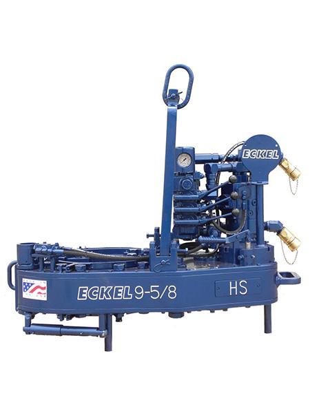
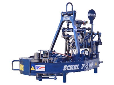
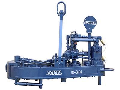
Casing Tongs provide make-up and break-out capabilities when running casing tubular in the drill hole to maintain well integrity. Casing tongs are available for various sizes from 5-1/2" to 36" and designed to handle high torque casing or lightweight casing. Available models: Standard, Hydra-Shift, High Torque, and Ultra High Torque with torques ranging from 15,000 ft-lbs up to 200,000 ft-lbs. Consistent operations between models reduce employee training.
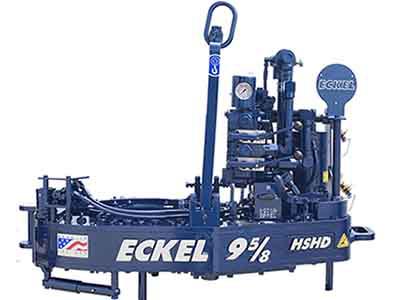
Eckel offers a full range of high-quality casing and tubing, drill pipe tongs for use in all types of oil and gas drilling, well completion, and well-servicing activities. Our tongs have been engineered for the high operational torques today"s that premium connections require. Eckel tongs continue to advance the technology of tool service and setting industry standards. Our tongs have improved crew efficiencies, such as our easy to open and close Radial Lock Door and our Hydra-Shift® speed shifting for speeding up turnaround time between connections. Eckel"s Torque turn control systems that monitor torque turn values when making up the tubular connection with any flaws in the make-up process are displayed.
Tongs - Power - BJ sucker rod tong adopts advanced sucker rod or tubing technology and has a compact structure, high reliability and is safe and convenient to operate.
Tongs - Power - New Carter Tool Co. Inc., CT93R Hydraulic powered tubing tong. Complete with 2-3/8" to 3-1/2" jaw assemblies, standard motor, torque gauge assembly, pressure relief valve... More Info
Tongs - Power - New Carter Tool Co., Inc. 5-1/2" CTSX Hydraulic Tubing Tong with heavy case and cover; complete with rigid hanger assy., suspension spring assy., front end control assy.,... More Info
Tongs - Power - New Carter Tool Co. Inc. M-Series power sucker rod tongs, complete with spring hanger assy., gate assy., front end control assy., pressure gauge assy., two 90 degree XH s... More Info
Tongs - Power - New Carter Tool Co., Inc. 4-1/2" RSX Hydraulic Tubing Tong with heavy case and cover; complete with rigid hanger assy., suspension spring assy., front end control assy., ... More Info
Tongs - Power - D D 58-93-2-R Power Tubing Tong is smaller, lighter, and faster than the Foster 5893R. The D D 58-93-2-R Tong is capable of gripping tubulars from 1 5/16" to 7" o.d. More Info
Tongs - Power - FARR TONG MODEL KT 14,000 RINEER GA37 MOTOR, LIFT VALVE ASSEMBLY TORQUE CAPACITY: 50,000 FT/LB SIZE RANGE 4 1.2-14 WITH SAFETY DOOR MOST SIZES OF FARR POWER TONGS ARE IN ... More Info
Tongs - Power - FARR TONG MODEL KT20,000 STAFFA 080 MOTOR, LIFT VALVE ASSEMBLY TORQUE CAPACITY: 50,000 FT/LB SIZE RANGE: 7-20 MOST SIZES OF FARR POWER TONGS ARE IN HOUSTON, IN STOCK READ... More Info
Tongs - Power - FARR MODEL KT5500 HYDRAULIC TUBING TONG C/W 2 SPEED RINEER MOTOR, SIZE RANGE: 2-3/8 IN. - 5-1/2 IN. OD, TORQUE RTED: 18,700 FT/LB C/W SAFETY DOOR MOST SIZES OF FARR POWER... More Info
Tongs - Power - FARR TONG MODEL KT5500 TORQUE CAPACITY: 18000 FT/LB SIZE RANGE: 2 1/16-5 1/2 OD WITH SAFETY DOOR MOST SIZES OF FARR POWER TONGS ARE IN HOUSTON, IN STOCK READY FOR IMMEDIA... More Info
Tongs - Power - FARR TONG MODEL KT5500 5 1/2 IN. TONG TORQUE CAPACITY: 18,000 FT/LB SIZE RANGE: 2 1/16-5 1/2 IN. OD, RINEER 15-13 MOTOR, HIGH TORQUE CLINCHER BACKUP TRIPLE VALVE ASSEMBLY... More Info
Tongs - Power - FARR TONG MODEL KT7585 TORQUE CAPACITY: 25000 FT/LB SIZE RANGE: 2 1/16-8 5/8 OD WITH SAFETY DOOR MOST SIZES OF FARR POWER TONGS ARE IN HOUSTON, IN STOCK READY FOR IMMEDIA... More Info
Tongs - Power - FARR TONG MODEL KT7585 8 5/8 IN. TONG TORQUE CAPACITY 25,000 FT/LB SIZE RANGE: 2 1/16-8 5/8 IN. OD, RINEER 15-15 MOTOR CLINCHER BACKUP, TRIPLE VALVE MOST SIZES OF FARR PO... More Info
Tongs - Power - FARR TONG MODEL LW9625 TORQUE CAPACITY 12000 FT/LB SIZE RANGE 2 7/8 -9 5/8 OD WITH SAFETY DOOR MOST SIZES OF FARR POWER TONGS ARE IN HOUSTON, IN STOCK READY FOR IMMEDIATE... More Info
Tongs - Power - Farrs newest tubular connection tool offers a significantly reduced rig footprint, while continuing to deliver power & uncompromising reliability. The simple design drast... More Info
Tongs - Power - Farr Canada"s newest tubular connection tool offers a significantly reduced rig footprint, while continuing to deliver power and uncompromising reliability. The simple de... More Info

I am chairman of the board, president and chief executive officer of Eckel International, the largest global providers of innovative and high performance hydraulic power tongs for the oil and gas industry. I am a second-generation family member involved in manufacturing of tongs. In 1993, as Eckel’s president, I launched an initiative to further reach out to Russia’s oil & gas needs. Today, I am directly responsible for the overall operations of the company, sales, and new market initiatives.
Since 1958 Eckel has been supplying power tongs to the worlds O&G industries– but how long have you been doing business in Russia and what specific solutions do you offer to the region?
Eckel has been conducting business in Russia since the 1978. In 1993, Eckel established an ongoing presence in Russia with CETCO as our local business partner. CETCO further extended our business across Russia & CIS as our local agent. We have observed strength in the Russia and CIS market, with solutions for drill pipe and casing operations.
Eckel specializes in the development of hydraulic power tongs for make-up and break-out of tubulars, with over 60 years of tubular connection experience. Our industry leading technology advancements are in some respects, a reflection on the industry requirements and their needs. Eckel has been in the process of designing tongs that required very high torques, advanced safety features, and automation.
Eckel in-house heating provides quality tempered steel while observing strict industry standards. This process assures high quality and rugged durable parts within Eckel power tongs. Eckel has won a world-wide reputation of providing first-class products that deliver years of trouble free service. Our tongs have operated trouble free in the harsh cold conditions of Western and Eastern Siberia and in the Far Northern Regions. Eckel’s hydraulic power units have a proven track record in some of the harshest surroundings in Russia such as the extreme hot and cold conditions of Russian and offshore environments.
Eckel has provided more than 500 Hydraulic Power Tongs to oil and gas companies and drilling contractors in Russia. In Russia, as well as in many other countries, the use of Corrosion Resistant Alloys (CRA) chrome tubulars are becoming more popular. Eckel is an industry leader in this specialized field tubular connections offering a line CHROMEBOSS® tongs along with Eckel Non-Marking True Grit® dies. True Grit® Dies utilize Tungsten Carbide grit coating which provides many more points of contact on the surface of the tubular than standard Pyramid Fine Tooth dies provide. Penetration depth less than half the depth that is permissible by the American Petroleum Institute (API). Eckel’s True Grit® dies use a dense Tungsten Carbide coating that is a metal like substance which does not flake or sheer off the face of the die. Operational on-site tests have shown that the life time of Eckel True Grit® wrap-around dies is three times longer than competing abrasive powder coated dies. The above equipment and components have been working in Russia several years and proved its advantages.
The hydraulic power tong market is very competitive in Russia, with both local and international suppliers competing for business. Why should a drilling contractor or operator consider using Eckel equipment?
Eckel has over 60 years of experience in this area, and is known for quality and reliability. Many of these tong manufacturers use the old Foster and Hillman Kelly that are 30-year-old designs. Eckel is at the forefront of this industry designing tongs that can handle today’s premium high torque connections. Our tong designs evolved to incorporate additional safety features, automation, and performance. Our new 7.25 HSHT-80 Drill Pipe / Casing and 9-7/8 HS-60 Casing tongs incorporates many of these features.
Eckel has been the leader in development of tubular gripping such as the development of larger wrap-around type dies for many of its tong models. Depending on the application, Eckel offers a coarse tooth, pyramid fine tooth, and our proprietary True Grit dies. Dies are available as rig die style and for thinner wall tubulars where point loading is a concern we offer wrap-around dies. All Eckel equipment is produced at our Odessa, Texas USA manufacturing facilities (ISO 9001:2008 certified) that encompasses 140,663 square feet (13068 square meters) ensures the highest quality.
Eckel equipment is popular world-wide as having shipped to over 100 countries. Eckel is best known for its value in reducing costs, safer tubular connection, reduced maintenance, and mitigated downtime.
Coralina Engineering and Capital Equipment and Trading Corporation (CETCO) has operations in Azerbaijan, and their specialists are intensely involved in this territory. CETCO specialist are successfully making inroads in the Azerbaijan territory offering Eckel power tongs and power units. Additionally, CETCO provides training, classes, assistance, and local experience in all practical aspects of tong operation and maintenance. CETCO is very optimistic for doing business in Kazakhstan region. We are actively working in this region at improving our relationships with existing and new customers.
Eckel continues to improve tong designs, reliability, functionality, and reduce operational costs to comply with today’s oil and gas industry requirements, and anticipate tomorrows industry requirement. A few examples are:
• One of the latest design of a new backup with Wedge Drive Type Tri-Grip which is used on the most of tong models. The WD Tri-Grip is a high-performance backup with no compromises that is available for specific applications. The Wedge Drive Tri-Grip handles the most demanding torques that larger casing and drill pipes demand.
• A new 7.25 HS HT-80 tong, that was introduced in the last half of 2016 for drill pipes and high torque casing pipes. We believe the 7.25 HS HT-80 tong is an extremely needed product for the Russian market. We anticipate the specifications of the tong will be of great interest and welcome surprise for our customers.
• In 2017, Eckel will release a couple of new product designs. The new 9-7/8 HS-60 Casing Tong available the 1st Quarter of 2017 offers efficient and reliable high rotational performance for torque turn jobs. With these high torque ratings, the 9-7/8 HS-60 Casing Tong is capable of properly handling all premium grade tubulars within its size range.
Available in the 2nd Quarter of 2017, a new tong positioner “Tong Handler” that is permanently mounted within the rig which provides a cost effective, safer, and reduced labor-intensive method of maneuvering tongs to the rotary table area on the rig floor.
Russian is a very large and great country with lots of attention dedicated to the oil and gas industries onshore and offshore. Today’s challenge is to have equipment that meets the needs and requirements of oil and gas companies and drilling contractors. Since our first tong delivery in 1978 and now with the assistance of Capital Equipment and Trading Corporation and Coralina Engineering, we have developed a good relationship with many Russian customers and a growing list of new customers. Oil production is not so easy however; we believe that we can solve the most difficult problems facing the oil and gas industries. I have enjoyed visiting Russia many times for work and pleasure.

Eckel 7 5/8 HDS-30 Tong When application demand a wide range of sizes, this tong handles pipe sizes 2 3/8 inches all the way to 7 5/8. Built around the 7 5/8 Standard, the 7 5/8 HD provides a thicker rotary gear for more added strength, an additional idler gear, a larger pinion gear, and stronger bearings for load bearing capacity and durability. 7 5/8 HDS CHROMEBOSS: the 7 5/8 HD comes standard with pivot style heads; however, upon ordering can be supplied with slide-heads which is designated as 7 5/8 HDS. the 7 5/8 HDS is part of our CHROMEBOSS series of tongs that is suitable for running corrosion-resistant alloy (CRA) tubulars. Two slide heads in the tong provide a consistent radial load on the tubular, reduced tubular deformation, and when combined with our pyramid fine tooth or True-GritTM wrap-around dies provides excellent gripping capabilities on corrosion-resistant alloy (CRA).
Eclel Established in 1958, Eckel is globally recognized as the leading manufacturer of hydraulic power tongs and hydraulic power units for the world"s oil and gas industries. We offer a full line of hydraulically operated drill pipe tongs, casing tongs, tubing tongs, hydraulic backups, hydraulic power units, and tong positioning equipment. Eckel delivers a comprehensive range of tongs from 2-1/16 through 36 in. for the most demanding onshore and offshore environments, offer a full range of high quality casing and tubing, drill pipe tongs for use in all types of oil and gas drilling, well completion and well servicing activities.
http://slidepdf.com/reader/full/13-38stdpdf 1/647/18/2019 13-38_STD.pdf
© Copyright 1989, Eckel Manufacturing Co., Inc. All rights reserved. No part of this manual may be reproduced, transmitted, transcribed, stored in a retrieval system, or translated into any language in any form by any means without the written permission of Eckel Manufacturing Co., Inc.
Eckel is a registered trademark of Eckel Manufacturing Co., Inc. Loctite is a registered trademark of Loctite Corporation 13-3/8 Standard Hydraulic Power Tubing Tong is covered by U.S. and Foreign Patents and Pending Patent Applications
Main Offices and Plant: International Sales Office: 8035 West County Road 480 N. Beltway 8 East, Suite 200 Box 1375, Odessa, Texas 79760 Houston, Texas 77060 Phone (432) 362-4336 Phone (713) 999-6680 Telex 74-5434 (ODS) Telex 77-4644 (HOU) FAX 432-362-1827 FAX 713-999-8707
http://slidepdf.com/reader/full/13-38stdpdf 2/647/18/2019 13-38_STD.pdf
General Operation ...............................................................................................18 Operating Controls and Gauges .......................................................................... 18 Pre-Operating Checks .........................................................................................18 Typical Operating Sequence ...............................................................................20
Section 4 - Servicing ........................................................................................................ .23 Daily Inspection ..................................................................................................24 Maintenance After Each Job ...............................................................................24 Lubrication ..........................................................................................................25 Tests and Adjustments ........................................................................................26
Section 5 - Troubleshooting, Repair and Overhaul .................................. .29 Troubleshooting ..................................................................................................30 Repair ..................................................................................................................31 Tong Overhaul ....................................................................................................31 M4D Motor Overhaul .........................................................................................32 A35 Valve Overhaul ...........................................................................................35
Section 6 - Parts List ....................................................................................................... .37 Parts List, Eckel 13-3/8 Standard Tong .............................................................. 38 Parts List, Clutch Assembly ................................................................................ 42 Parts List, Pinion Idler Assembly .......................................................................43 Parts List, Pinion Assembly ................................................................................ 44 Parts List, Rotary Idler Assembly ....................................................................... 45 Parts List, M4D Motor Assembly .......................................................................46 Parts List, A35 Valve Assembly .........................................................................48 Parts List, Hydraulic Cam Backup ...................................................................... 59 Parts List, Tong Suspension ................................................................................ 56 Parts List, Door Interlock Assembly ................................................................... 57 Microswitch Assembly .......................................................................................60
http://slidepdf.com/reader/full/13-38stdpdf 3/647/18/2019 13-38_STD.pdf
http://slidepdf.com/reader/full/13-38stdpdf 5/647/18/2019 13-38_STD.pdf
INTRODUCTION This manual describes the function, operation and maintenance of the Eckel 13-3/8 Standard Hydraulic Power Casing Tong. This section provides a functional description, system specifications, and a description of options and accessories available. Section 2 through 5 present the operating and maintenance aspects of the tong and Section 6 provides a fully illustrated parts list. The 13-3/8 Standard Tong, Figure 1-1, handles casing sizes as small as 4 inch and as large as 13-3/8 inches diameter. The open-throat design, combined with high-speed operation, assures both ease and speed in tubular handling. A safety door on the open throat helps insure against accidents. The following paragraphs describes the functions of the tong during tubular make-up or break-out operations.
8 3 3 L1 K GEAR TRAIN, CLUTCH DETAILS (INSIDE HOUSING)
Figure 1-1 Functional Elements of the 13-3/8 Standard Tong 13-3/8 Standard Tong is covered by U.S. and Foreign Patents and Pending Patent Applications
http://slidepdf.com/reader/full/13-38stdpdf 6/647/18/2019 13-38_STD.pdf
FUNCTIONAL DESCRIPTION Operating from a hydraulic power unit, the power tong provides torque of 22,000 ft-lbs. The heart of the unit is a head-closing system which forces the heads together and rotates them by means of a cam-type rotary gear. The rotary gear is driven by a two-speed gear train powered from a vane-type hydraulic motor. In operation, the tong is suspended over the well bore on a chain bridle. Snub lines restrain the tong from moving around the pipe as torque is applied. HYDRAULIC DRIVE SYSTEM. Figure 1-2 is a hydraulic schematic of the drive system. Hydraulic pressure from a separate power unit is applied through screw-type hose connectors having built-in check valves. To prevent cross-connection of the hoses, the pressure hose from the power unit is designed to mate with a 1-inch connector and the return hose mates with a 1-1/4 inch connector. Connection of the hoses opens the check valves to provide hydraulic pressure to the tong. The tong control levers acts as a throttle valve for the unit. Pushing the lever applies pressure to drive the motor in a forward direction (for make-up operation) and pulling the lever applies pressure in a reverse direction (for break-out operation). While the lever is in a neutral position, fluid circulates freely through the valve and back to the return line. Refer to Section 3 for tong control lever positions.
An adjustable relief valve permits adjustment of the operating pressure at the tong if desired, and a built-in pressure gauge indicates the operating pressure at all times. The maximum pressure available, of course, depends upon the power unit. A power unit capable of delivering 2,500 PSI and 30 GPM and 1000 PSI at 65 GPM is necessary in order to obtain the maximum rated output of the power tong. A hydraulic motor is mounted on the top tong plate through a motor adaptor, and the
other hydraulic plumbing components are also mounted on the top tong plate. GEAR TRAIN AND CLUTCH FUNCTION. Closure and rotation of the pipe-gripping heads are accomplished by means of a large rotary gear having its inner diameter formed into a double cam surface. This topic explains how mechanical power is transmitted from the hydraulic motor to turn the rotary gear in either direction. Gear Train Elements. The gear train, Figure 1-3, comprises a motor gear, the clutch assembly, pinion assembly, pinion idler, two rotary idlers and the rotary gear. The rotary gear rides within a circle of dumbbell rollers that support the gear. The selected high- or low-speed clutch gear engages the corresponding high or low-speed pinion gear, and the
http://slidepdf.com/reader/full/13-38stdpdf 7/647/18/2019 13-38_STD.pdf
pinion output gear drives the two pinion idlers gears whin in turn drives the two rotary idlers. In driving the rotary gear, two rotary idler gears are necessary to bridge throat cut out gap. Clutch. The clutch assembly (Figure 1-3) provides high- or low-speed operation, allowing faster operation when high torque is not required. When higher torque is needed, the low-speed gear permits the operator to slow the speed down and increase the torque. The operator shifts the speed by raising or lowering a shifter lever on top of the tong. As shown in the illustration, lifting the shift lever lifts the shifting yoke, which lifts the shifting collar. In this position, the shifting collar mechanically couples the clutch shaft with the high-speed clutch gear. Lowering the shifting lever lowers the shifting yoke which lowers the shifting collar, thereby mechanically coupling the clutch shaft with the low-speed clutch gear. Then the selected clutch gear drives the corresponding pinion gear as previously described. An adjustable spring detent on the shifting shaft holds the yoke and shifting lever in the selected position until again moved by the operator. HEAD OPERATIONS. The sliding heads are enclosed within the rotary gear by the top and bottom cage plates. The heads are closed, rotated and opened by the combined actions of the rotary gear, brake bands and backing pin. Rotary Gear/Head Functions. During make-up operations, the pipe to be turned is first enclosed in the tong, and the throat safety door is closed. Then with the backing pin in the make-up position (described later) the operator pushes the tong control lever forward to cause the heads to bite and rotate the pipe. To release the heads and back off from the pipe, the operator pulls the tong control lever outward. During break-out operations, the backing pin is placed in the break out position so that the heads bite in the reverse direction (see Backing Pin Function). Then the operator pulls the tong control lever to cause the heads to bite and break out the pipe. Finally, he pushes the lever forward to release the heads and back them off the pipe. As illustrated in Figure 1-4, the head-biting action is a function of the rotary gear inner surface cam design. When the rotary gear begins to rotate, the head rollers roll up on the cam surface and force the sliding heads inward until the heads bite the pipe. Further rotation then turns the pipe to make-up (or break-out) the joint.
http://slidepdf.com/reader/full/13-38stdpdf 8/647/18/2019 13-38_STD.pdf
Rotary Gear and Head Cage Rotation. Figure 1-5 illustrates the cam follower rollers that permit the semi-independent rotation of the cage plates and rotary gear. The figure illustrates how the top cage plate is free to rotate on a ring of cam follower rollers following a groove in the rotary gear. The rotary gear is turned independently within a circle of dumbbell rollers.. The bottom cage plate rotates on a ring of cam follower rollers identically with the top cage plate. This plate is bolted to the top cage plate to enclose the heads. The heads are forced in to bite the pipe as brought about by the cam action of the rotary gear on the head rollers. Brake Band Function. Consider again the actions of the rotary gear cam and heads in view of the freedom that the cage plates have to rotate. It becomes evident that, if the
BACK CAGE PLATE BOLT CAM FOLLOWER TOP TONG PLATE TOP CAGE PLATE
http://slidepdf.com/reader/full/13-38stdpdf 9/647/18/2019 13-38_STD.pdf
Brake Bands and Safety Door cage plates have unrestrained freedom to rotate, the heads will simply move with the rotary gear and will not cam up on the rotary cams to force the biting action. Figure 1-6 illustrates how brake bands are placed around the cage top and bottom plates to exert continuous friction on these plates and to restrict their freedom to move. Thus it is evident that the brake bands do not permit the cage plates (and heads) to turn freely when the rotary gear turns. Rather, the cage plates are held stationary as the head rollers roll up onto the cam surfaces to force the heads in against the pipe. As the heads bite the pipe, the friction of the brake bands is overcome. Then the cage plates begin to rotate with the rotary gear, thus turning the pipe that is now gripped firmly by the heads. Backing Pin Function. The backing pin shown in Figure 1-5 permits the heads to bite in the forward direction for make-up and in the reverse direction for break-out. When the pin is placed in the left-hand hole, forward operation causes the heads to bite and rotate to make up the joint. However, reverse operation causes the backing lug to strike the backing pin and force the cage plates around with the rotary gear. Thus, in the reverse direction, the head rollers cannot cam up on the rotary cam and the heads do not bite. If the backing pin is placed in the right-hand hole, the opposite action occurs and reverse operation causes the heads to bite, while forward operation causes the backing lug to strike the backing pin and force the head cage around with the rotary gear, thus inhibiting the heads from biting in the forward direction. In summary then: for make-up, the backing pin is placed in the left-hand hole and the heads bite in forward direction; and for break-out, the backing pin is placed in the right- hand hole and the heads bite in the reverse direction. Open Throat and Safety Door. The open throat design permits ease of operation by permitting entry of vertical pipe that projects above the level of the tong. For safety purposes it is necessary that the throat opening be closed during operation to prevent personnel injuries or damage to the equipment. A safety door (Figure 1-6) serves both to close off the front during operation and to provide an extra margin of support for the housing during high-torque operation. An optional Door Interlock (Figure 6-9) device adds additional margin of safety, preventing the tong from operating while the tongs door is open.
http://slidepdf.com/reader/full/13-38stdpdf 10/647/18/2019 13-38_STD.pdf
SPECIFICATIONS The specifications for an operating tong must consider the hydraulic power unit as well as the tong itself. HYDRAULIC POWER UNIT SPECIFICATIONS. The power tong is designed to be powered by a hydraulic power unit capable of delivering at least 2500 pounds per square inch (PSI) for maximum rated operating torque. At least 65 gallons of hydraulic oil per minute, depending upon the power unit used, are required to operate the tong at maximum RPM. TONG SPECIFICATIONS. Table 1-1 list the specifications for the Eckel 13-3/8 Standard Casing Tong.
OPTIONS AND ACCESSORIES Options for the 13-3/8 Standard Tubing Tong include lift cylinder with lift cylinder control, spring hanger, torque gauge, manual backup and door interlock. The optional items are described in the following paragraphs. LIFT CYLINDER AND CONTROLS. A lift cylinder as illustrated in Figure 2-3 is optionally supplied with the 13-3/8" tong. This cylinder provides a means for raising and lowering the tong during operations. Lift Cylinder. While the lift cylinder may be connected directly to the tong bridle, it is suggested that the optional spring hanger be inserted between the lift cylinder and theTable 1-1Specifications Eckel 13-3/8 Standard Tong
Torque: Dimensions: High Gear (Range) ...................... 4,400 ft/lbs Length ........................ 61 inches (1549 mm) (5,966 nm) Overall Width ..................34 Inches (864mm) Low Gear (Maximum) ............... 22,000 ft/lbs Pipe Space Required ... 7.5 inches (191 mm) (29,828 nm) Max. Elevator Diameter ............... (Unlimited- Tong comes off Pipe) Torque Handle Lengths: Pipe C.L. to Anchor C.L. 36 Inches (914 mm) Standard .................................. 36" (914 mm) Weight: RPM: Approximately ......... 1,260 Pounds (571 kg.) High ..................... 85 at 65 GPM (250 L/min) Low ...................... 16 at 65 GPM (250 L/min) Heads Available: For Tubing Size O.D.: .... 4", 4-1/2", 5", 5-1/2" Hydraulic Requirements:* 6-5/8", 7", 7-5/8", 8-5/8" 65 G.P.M. (250 L/min) at 1,000 P.S.I. (68 bar) 9-5/8", 10-3/4",11-3/4",13-3/8" 30 G.P.M. (113 L/min) at 2,500 P.S.I. (172 bar) NOTE: Any size head between 4" and 13-3/8" may Hyd. Oil Operating Temperature: be specified as needed. Normal .................................. 130° F. (54° C) Maximum .............................. 180° F. (82° C) * These are average requirements for a new tong. There may be some variations from tong to tong.
http://slidepdf.com/reader/full/13-38stdpdf 11/647/18/2019 13-38_STD.pdf
bridle to permit tong movement during make-up or break-out operations without exerting undue stress on the bridle and dies. Lift Cylinder Controls. When a lift cylinder is ordered with a tong, the tong contains an additional control lever for controlling the lift cylinder movement. The control lever- operated valve is identical to the tong operating control lever. This lever is illustrated in Figure 3-1 and its operation is shown in Figure 3-2 and Table 3-1. Pulling the control lever outward provides hydraulic pressure from the hydraulic power unit to operate the lift cylinder upward, and thus raise the tong. While pushing the control lever forward operates the cylinder downward to lower the tong. The center lever position is the neutral position and does not operate the cylinder in either direction. The maximum travel of the lift cylinder is 6 feet. SPRING HANGER. The optional spring hanger (Figure 2-3) is designed to permit the tong to move up or down to allow for thread length in make-up and break-out operations. When used, the spring hanger should be attached directly to the tong bridle ring and used as a hanger for the tong. TORQUE GAUGE ASSEMBLY. The optional torque gauge assembly (Figure 2-2) is used to measure the torque exerted in make-up or breakout operations. Consisting of a hydraulic cylinder and torque gauge connected together by a pressure hose, the torque gauge assembly senses and indicates the torque developed during an operation. For operation, the hydraulic cylinder is connected by a shackle to the rear of the tong; and a snub line is connected to the cylinder. The snub line is tied off to a solid part of the rig structure to form an angle of 90° in order to indicate accurate torque readings. HYDRAULIC CAM BACKUP AND CONTROLS. A hydraulic backup tool as illustrated in Figure 1-8 is optionally supplied with the 5-1/2 Standard Tong. In opera- tion this tool provides a backup when in break-out or make-up situations. The specifica- tions for the hydraulic backup are supplied in Table 1-2.
100 7 176 238 880 1193 200 14 352 477 1760 2386 300 21 528 715 2640 3579 400 28 704 954 3520 4772 500 34 880 1193 4400 5965 750 52 1320 1789 6600 8948 1000 69 1760 2386 8800 11931
1250 86 2200 2982 11000 14913 1500 103 2640 3579 13200 17896 1750 121 3080 4175 15400 20879 2000 138 3520 4772 17600 23862 2250 155 3960 5369 19800 26845 2500 172 4400 5965 22000 29827
These figures are estimated average torque with mechanical and hydraulic losses taken into account. Actual performance will depend upon the condition of the tong.
http://slidepdf.com/reader/full/13-38stdpdf 12/647/18/2019 13-38_STD.pdf
Capacity ........... 4" - 14-3/8" (101.6 - 365.1 mm) Max. Holding Torque 22,000 ft-lbs (29,827 Nm) Max. Pressure ................ 3,000 P.S.I. (207 Bar) Handle Length .......................36 inch (914 mm)
Dimensions (Tong and Backup): Length ......................... 61 inches (1550 mm) Height ..................... 58.5 inches (1486 mm) Overall Width .............. 43 inches (1092 mm)
Weight: Approximately (Tong and Backup) .... 2,950 lbs (1,338 kgs)
Heads Available: For Tubing Size O.D. ........ 4", 4-1/4", 5-1/4", 5-1/2", 5-3/4", 6-1/2", 6-5/8", 7-3/8", 8-5/8", 9-5/8", 10-3/4", 11-3/4",13-3/8",14-3/8
HYDRAULIC CAM BACKUP. The hydraulically operated backup tool, in utilizing the same biting principal as the power tong, uses a cam and pivot head arrangement to insure slip-free operation. The stinger part of the backup, extending from the rear of the unit is inserted into the torque bracket mounted on the underside of the tong. This method of hook up prevents movement of the tong about the pipe during torquing operation. Between the stinger and bracket is located the torque gauge compression load cell. During make-up or break-out operations, the tong unit rotates slightly causing the stinger to compress the load cell, torque readings are available in make-up or break-out, depending on position of load cell in bracket. The load cell should be on the operator side of the backup stinger for make-up and for break-out the load cell would be inserted on the opposite side of the backup stinger to register the torque. The compression force is translated to torque which is indicated on the torque gauge connected to the load cell. The hydraulic cam type backup requires a 36-inch torque gauge handle which offers direct reading of torque between the backup and the tong. The hydraulic backup is suspended at an adjustable level below the power tong by means of three hanger legs and springs. This set up allows the backup to remain stationary while the power tong moves vertically to compensate for thread travel of the connection. Hydraulic Backup Controls. When a hydraulic backup is ordered with a tong, the tong contains an additional control lever for controlling the backup and a directional valve for controlling the rotation of the backup. These levers are illustrated in Figure 3-1 and its operation is shown in Figure 3-2 and Table 3-1. Pushing the control lever inward provides hydraulic pressure from the hydraulic power unit to rotate the backup cage plates clockwise for make-up or counter-clockwise for break-out and engages the heads on the pipe. Pulling the control lever disengages the backup heads from the pipe. The
http://slidepdf.com/reader/full/13-38stdpdf 13/647/18/2019 13-38_STD.pdf
Non Upset & External Upset Integral Joint Connections Tong and Cam-Type Backup Cam-Type Tong and Cam-Type Backup Biting Locations Backup Dies Biting Locations
Figure 1-9 Make-up and Break-out Biting Locations backup cage plates are always rotated in the direction that the tong will turn and by using the directional control lever the operator controls which direction the backup rotates. Adjusting Backup Spacing. The vertical spacing between the backup and tong is adjustable in steps using different sets of holes in the hanger legs for the bolts which hold the backup hanger springs in position. There are four sets of holes located at various distances below the tong. The distance of these holes from the midpoint of the tong dies to midpoint of backup dies is described in Table 1-4. Close spacing between the backup and tong is desirable from the standpoint of insuring the closest possible length of contact between the dies and pipe. This is particular important with drill pipe where short upsets may be encountered. Also, close spacing is beneficial in reducing twisting forces in the tong and backup structures. On the other hand, the design provides spacing when it is necessary to straddle extra long couplings or upsets as is required in make-up operations. Figure 1-9 illustrates the proper biting locations for make-up and break-out. DOOR INTERLOCK. The door interlock device is an optional added safety feature that Eckel Manufacturing Co., Inc. offers with its tongs. The door interlock device impedes hydraulic •uid from reaching the motor when the tongs door is open thus preventing tong operation. RPM CONTROL. The RPM Control is a •ow divider that decreases the amount of hydraulic •uid that reaches the tong, the remaining •uid is returned to the reservoir. By decreasing the amount of •uid reaching the tong the operator is able to control the maximum RPM"s the tong will deliver.
Hole Set Distance Top (First) 9.75" Second 14.75" Third 19.75" Fourth 24.75"
http://slidepdf.com/reader/full/13-38stdpdf 14/647/18/2019 13-38_STD.pdf
http://slidepdf.com/reader/full/13-38stdpdf 15/647/18/2019 13-38_STD.pdf
GENERAL CONSIDERATIONS Installation of the power tong requires consideration of the tong itself, the hydraulic power unit to be used, and the accessories that will be required. TONG CONSIDERATIONS. The 13-3/8 Standard Tubing Tong is capable of handling pipe sizes from 4 inch to 13-3/8 inch in outside diameter. The heads to be used with the tongs, of course, depend upon the size pipe being used. Refer to Table 1-1, Specifica- tions for the various heads provided with the tong. Head Installation. Install the correct size heads according to the following procedure.
! WARNING: Do not attempt to change heads with power unit in operation. Failure to Warning observe proper precautions could be extremely hazardous and result in loss of a hand or arm. 1. Remove two head pivot bolts, Figure 1-6. 2. Swing in and lift out the heads. 3. Select proper heads for pipe to be worked and install in head cage in reverse order of steps 1 and 2.
Tong Space Requirements. You should consider the space requirements of the tong, both in storage and in operation. Figure 2-1 give the tong dimensions. POWER CONSIDERATIONS. Before installing the tong for field operations, you must be sure that an appropriate power unit is available and that the power unit is adjusted for use with the tong. To operate the tong within its full capability, the relief valve on the hydraulic power unit should be adjusted to 3000 pounds per square inch. Refer to power unit manual for the procedure on power unit valve adjustments. Accessory Considerations. Tong installation requires that the necessary accessories be available for the type of operation to be performed.
22.5 IN 571.5 MM 34 IN 13.625 IN 863.6 MM 346 MM
A. TONG LENGTH & HEIGHT B. TONG WIDTH & THROAT WIDTH 61 in. 1550 mm
43 in. 58.5 in. 1092 mm 1486 mm
36 in. 914 mm Torq ue Hand le
http://slidepdf.com/reader/full/13-38stdpdf 16/647/18/2019 13-38_STD.pdf
Figure 2-2 Torque Gauge Installation Figure 2-3 Installation of Torque Gauge Assembly. Measurement of the applied torque Tong Installation requires a torque gauge assembly installed on the equipment. Once installed, the torque gauge assembly becomes an integral part of the unit. To install the torque gauge on the tong, proceed as follows: 1. Using three mounting screws, mount torque gauge into position on torque gauge plate, Figure 2-2. 2. Route hose to avoid interference with tong operation. 3. Secure one side of hydraulic cylinder to snub line eye on rear of tong. WARNING: The tong should be secured for both make-up or break-out operation, by ! Warning utilizing the snub line. If this is not done, the tong may be thrown against operator causing physical harm. 4. Attach the other end of the snub line to a part of the rig structure that is rigid enough to withstand the line-pull. Please note that an angle of 90° must be maintained between the tong and snub line for the gauge to indicate accurate torque readings. Lift Cylinder Considerations. If the tong suspension line is not counter balanced, a lift cylinder should be used. Also, if an Eckel lift cylinder is to be used, the tong must be equipped with an additional control valve and lever. The lift cylinder should be sus- pended from the line that will hang the tong as shown in Figure 2-3. Spring Hanger Consideration. A typical spring hanger installation is shown in Figure 2-3. For a counter-balanced support line, the spring hanger is suspended from the line. When a lift cylinder is used, the spring hanger may be installed above or below the lift cylinder as described. HYDRAULIC BACKUP CONSIDERATIONS. The hydraulic backup is capable of handling pipe sizes from 4 inch to 14-3/8 inch in outside diameter. Any significant difference between actual pipe diamter and design diamter may result in failure of the heads to take an initial bite, slipping under torque, and other problems. HANGING THE TONG. The tong is transported to the well site and hung into position as illustrated in Figure 2-3 and as follows: CAUTION: Do not hook lift-line on turnbuckels. Be sure bridle chains are clear of valves Caution and controls. 1. Connect bridle to tong and verify tong is snubbed for both make-up and break- out operations. 13
http://slidepdf.com/reader/full/13-38stdpdf 17/647/18/2019 13-38_STD.pdf
2. Using the cat line on drilling rig, or a specially rigged line, lift tong to desired height in the work area and secure. Be sure the lift cylinder or counter-balance system is properly in place and functioning. 3. Adjust the turnbuckles as necessary to level the tong to ensure an even bite on the casing. This is done by first placing tong on pipe, and taking all slack out of the snub line. 4. Connect snub line to hydraulic cylinder of torque gauge assembly to restrain tong roation and to provide torque readings for make-up or break-out opera- tions. 5. Secure other end of snub line to a solid part of rig at a 90-degree angle from the tongs center line.
CONNECTING HYDRAULIC HOSES The hydraulic couplings, Figure 2-3, contain check valves to prevent loss of hydraulic fluid when the lines are disconnected. The check valves are closed until the hydraulic hoses are connected. Proper tightening of the hydraulic hose connectors opens these check valves. However, pressure may be in the tong when the lines are disconnected so that the valves resist opening. In such case, the connectors may seem to reach the end of thread travel when, in reality, the check valve operation is restricting further tightening. When making up these connections you should be sure that you have tightened the couplings tight and have not simply reached a "false" tightening due to the resistance of the check valves. Connect the hoses as follows: 1. Disable power unit, never connect or disconnect hoses when unit is in opera- tion. CAUTION: To be sure connectors are completely tight, first tighten them until travel is restricted and the end of the thread travel appears to be reached. Then try to tighten the Caution connector further to be sure first restriction was not a false tightness. Then continue to tighten the fitting until connection is tight. 2. Hook up pressure hose to one-inch fitting on tong by forcing connectors together while turning the wing nut. 3. Hook up return hose from power unit to 1-1/4 inch connector on tong, as described in step 2. 4. If a lift cylinder is used, hook up the hose from lift cylinder to connector provided on tong. 5. Start power unit and allow hydraulic flui


 8613371530291