
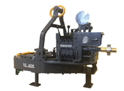
hydraulic power tong 40 000 factory

Casing Tongs provide make-up and break-out capabilities when running casing tubular in the drill hole to maintain well integrity. Casing tongs are available for various sizes from 5-1/2" to 36" and designed to handle high torque casing or lightweight casing. Available models: Standard, Hydra-Shift, High Torque, and Ultra High Torque with torques ranging from 15,000 ft-lbs up to 200,000 ft-lbs. Consistent operations between models reduce employee training.
In assembling a string of tubing for an oil well, a long series of pipe sections are screwed together, usually by means of a power tongs. Conventional power tongs have jaws with serrated faces that are designed to bite into the pipe surface. These jaws are usually cam operated, so that their closing force is roughly proportional to the tongs torque. Such an arrangement, however, is unsuitable for certain modern tube materials which are particularly soft. This is true for example, for some high chromium pipes designed for corrosion resistance rather than strength, and for fiber glass tubing now being developed. There are also pipes having protective coatings designed to protect the underlying material from corrosion by hydrogen sulfide and other subterranean chemicals. Some tubing costs on the order of one thousand dollars per foot, and a string is typically thousands of feet long. Plainly, it is critical not to damage tubing while making up a string, and to avoid any surface damage that could reduce service life.
Consequently, there is a need for power tongs whose jaws will not injure the surface of tubing and yet can deliver to the tubing adequate torque, which may be several thousands foot-pounds. The approach taken by this invention is to provide jaws actuated by hydraulic linear motors so that jaw pressure can be accurately controlled.
Hydraulically biased jaws on power tongs are known in the prior art; see, for example, U.S. Pat. Nos. 3,796,418, 3,921,473, 4,057,887 and No. 4,402,293. None of these however, provide means for independently controlling the jaw force.
It is therefore an object of this invention to construct a power tongs having jaws designed not to bite into the surface of pipe or tubing and yet able to transfer sufficient torque to the tubing.
Another object is to control jaw pressure independent of tongs torque. These and other objects will be apparent from the following description of a preferred embodiment of the invention.
The foregoing objects are met, according to this invention, by a power tongs having at least one hydraulically biased jaw, and means for controlling the hydraulic pressure delivered to the jaw. With this arrangement, smooth-faced jaws made of soft material can be used, and purely frictional engagement with the pipe surface suffices to make up the string.
As shown in FIGS. 1 and 2, an apparatus embodying the invention comprises a power tongs 10 including a motor 12 driven by hydraulic fluid or other medium. Means (not shown) are provided for manually or automatically controlling the tongs motor. The tongs motor 12 is connected through gearing, not shown, to a rotary head 14, to which the pipe gripping assembly 20 of the invention is attached. The gripping assembly comprises plural (preferably three) segments 22a, 22b, 22c equally spaced around a vertical axis corresponding to that of a pipe P that is to be torqued.
Referring to FIG. 2, at least one segment, 22b, includes at least one (preferably two) short stroke hydraulic cylinders 32, each containing a piston 34 for driving a jaw 36 radially inward against the pipe P. The jaw 36, which is mounted in a slot 38 for free movement only in the radial direction, is preferably made of a soft material, such as aluminum, so that it will not scratch through pipe coatings, or damage pipes made of soft material. The hardness of the jaws thus may vary, according to the intended pipe material. For fiberglass pipe, the jaws may be harder than the pipe.
The gripping face 40 of each jaw is (FIG. 3) preferably smooth; that is, without teeth or other contours that might cut into and damage the pipe surface. This is particularly important for coated pipe, but as an alternative, the jaw surfaces may be "corrugated" as illustrated in FIG. 4. For fiberglass pipe, where surface damage can be tolerated, a serrated, knurled or toothed surface (FIG. 5) is preferred.
FIG. 6 shows a schematic of the fluid circuit of this invention. An external compressed air source 42 is connectable, via a quick-connect fitting 44, to an air-driven hydraulic pump 46 mounted on the gripping device beneath an oil reservoir 48. The pump outlet communicates with the cylinders 32, in parallel, through a check valve 50 which prevents retrograde flow. A manually adjustable pressure relief valve 52 serves as means for controlling fluid pressure by bleeding excess pressure back to the reservoir. A manually operable, normally closed valve 54 can be opened to bleed all pressure from the cylinders 32 when it is desired to release the pipe. A gauge 56 indicates the actual cylinder pressure.
In operation, the tongs are brought, laterally, over a pipe joint P, FIG. 1, and the gripping assembly 20 is closed around the pipe by means of the latch 26. Air pressure from source 42 is then applied via fitting 44, whereupon the pump 46 generates hydraulic pressure within the cylinders 32, which pressure is limited by the setting of the pressure relief valve 52. The check valve 50 maintains the cylinder pressure after the air source is disconnected, whereafter there are no external hoses or other connections to the gripping device that would prevent it from rotating. The tongs are then activated, causing the gripping device and the pipe P to rotate with the rotary head until the desired torque is reached. Various torque limiters, such as those disclosed in U.S. Pat. Nos. 4,552,041 and 4,579,024, may be used to control the tongs, if desired.
To release the pipe P, the valve 54 is opened, allowing the pistons 34 to be retracted by their biasing springs as fluid escapes to the reservoir 48. The device may then be unlatched, and the tongs are then removed from the pipe.
The adjustability of the relief valve 52 enables one to control the actual clamping jaw force, independently of tongs torque. It is therefore possible, with this invention, to avoid excessive clamping pressures that could cause surface or structural damage to soft pipes. The service life of some of the most expensive tubing can thus be markedly prolonged. The pressure reaching cylinders 32 is limited by means of the adjustable pressure relief valve 52, which is set to a pressure that is a function of pipe material, size, makeup torque and possibly other factors. The upper pressure limit, for a given size jaw, is necessarily that pressure which would collapse or crush the pipe. However, the jaws may be made as long as desired; e.g., one foot long or more, so as to distribute jaw load over a greater surface area. As a result, by judicious design choice, any desired torque can be transferred to the pipe by the gripping assembly, without damaging the pipe surface.
With this invention, jaw forces are positively controlled and limitied, without regard to the tongs torque. This is in complete contrast to traditional cam-operated jaws, where jaw force is roughly proportional to tongs torque and is usually unknown in magnitude.
We have found that aluminum jaws with no teeth or surface irregularities whatsoever can be used with this invention. As long as the hydraulic cylinder pressure is properly set and controlled, such jaws are capable of developing very high torques through purely frictional engagement with the pipe surface. Since contact with the pipe is purely compressional, surface discontinuities are not created.
Various other modifications will occur to those of skill in the art, to create other uses for the invention. For example, the gripping device could be used in a (non-rotary) backup tongs. Also, high pressure water could be used in place of hydraulic fluid to drive the pistons 34, and such a modification would avoid the release of oil into the environment.
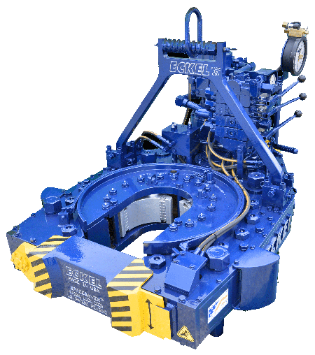
I am chairman of the board, president and chief executive officer of Eckel International, the largest global providers of innovative and high performance hydraulic power tongs for the oil and gas industry. I am a second-generation family member involved in manufacturing of tongs. In 1993, as Eckel’s president, I launched an initiative to further reach out to Russia’s oil & gas needs. Today, I am directly responsible for the overall operations of the company, sales, and new market initiatives.
Since 1958 Eckel has been supplying power tongs to the worlds O&G industries– but how long have you been doing business in Russia and what specific solutions do you offer to the region?
Eckel specializes in the development of hydraulic power tongs for make-up and break-out of tubulars, with over 60 years of tubular connection experience. Our industry leading technology advancements are in some respects, a reflection on the industry requirements and their needs. Eckel has been in the process of designing tongs that required very high torques, advanced safety features, and automation.
Eckel in-house heating provides quality tempered steel while observing strict industry standards. This process assures high quality and rugged durable parts within Eckel power tongs. Eckel has won a world-wide reputation of providing first-class products that deliver years of trouble free service. Our tongs have operated trouble free in the harsh cold conditions of Western and Eastern Siberia and in the Far Northern Regions. Eckel’s hydraulic power units have a proven track record in some of the harshest surroundings in Russia such as the extreme hot and cold conditions of Russian and offshore environments.
Eckel has provided more than 500 Hydraulic Power Tongs to oil and gas companies and drilling contractors in Russia. In Russia, as well as in many other countries, the use of Corrosion Resistant Alloys (CRA) chrome tubulars are becoming more popular. Eckel is an industry leader in this specialized field tubular connections offering a line CHROMEBOSS® tongs along with Eckel Non-Marking True Grit® dies. True Grit® Dies utilize Tungsten Carbide grit coating which provides many more points of contact on the surface of the tubular than standard Pyramid Fine Tooth dies provide. Penetration depth less than half the depth that is permissible by the American Petroleum Institute (API). Eckel’s True Grit® dies use a dense Tungsten Carbide coating that is a metal like substance which does not flake or sheer off the face of the die. Operational on-site tests have shown that the life time of Eckel True Grit® wrap-around dies is three times longer than competing abrasive powder coated dies. The above equipment and components have been working in Russia several years and proved its advantages.
The hydraulic power tong market is very competitive in Russia, with both local and international suppliers competing for business. Why should a drilling contractor or operator consider using Eckel equipment?
Eckel has over 60 years of experience in this area, and is known for quality and reliability. Many of these tong manufacturers use the old Foster and Hillman Kelly that are 30-year-old designs. Eckel is at the forefront of this industry designing tongs that can handle today’s premium high torque connections. Our tong designs evolved to incorporate additional safety features, automation, and performance. Our new 7.25 HSHT-80 Drill Pipe / Casing and 9-7/8 HS-60 Casing tongs incorporates many of these features.
Eckel has been the leader in development of tubular gripping such as the development of larger wrap-around type dies for many of its tong models. Depending on the application, Eckel offers a coarse tooth, pyramid fine tooth, and our proprietary True Grit dies. Dies are available as rig die style and for thinner wall tubulars where point loading is a concern we offer wrap-around dies. All Eckel equipment is produced at our Odessa, Texas USA manufacturing facilities (ISO 9001:2008 certified) that encompasses 140,663 square feet (13068 square meters) ensures the highest quality.
Coralina Engineering and Capital Equipment and Trading Corporation (CETCO) has operations in Azerbaijan, and their specialists are intensely involved in this territory. CETCO specialist are successfully making inroads in the Azerbaijan territory offering Eckel power tongs and power units. Additionally, CETCO provides training, classes, assistance, and local experience in all practical aspects of tong operation and maintenance. CETCO is very optimistic for doing business in Kazakhstan region. We are actively working in this region at improving our relationships with existing and new customers.
Eckel continues to improve tong designs, reliability, functionality, and reduce operational costs to comply with today’s oil and gas industry requirements, and anticipate tomorrows industry requirement. A few examples are:
• One of the latest design of a new backup with Wedge Drive Type Tri-Grip which is used on the most of tong models. The WD Tri-Grip is a high-performance backup with no compromises that is available for specific applications. The Wedge Drive Tri-Grip handles the most demanding torques that larger casing and drill pipes demand.
• A new 7.25 HS HT-80 tong, that was introduced in the last half of 2016 for drill pipes and high torque casing pipes. We believe the 7.25 HS HT-80 tong is an extremely needed product for the Russian market. We anticipate the specifications of the tong will be of great interest and welcome surprise for our customers.
• In 2017, Eckel will release a couple of new product designs. The new 9-7/8 HS-60 Casing Tong available the 1st Quarter of 2017 offers efficient and reliable high rotational performance for torque turn jobs. With these high torque ratings, the 9-7/8 HS-60 Casing Tong is capable of properly handling all premium grade tubulars within its size range.
Available in the 2nd Quarter of 2017, a new tong positioner “Tong Handler” that is permanently mounted within the rig which provides a cost effective, safer, and reduced labor-intensive method of maneuvering tongs to the rotary table area on the rig floor.
Russian is a very large and great country with lots of attention dedicated to the oil and gas industries onshore and offshore. Today’s challenge is to have equipment that meets the needs and requirements of oil and gas companies and drilling contractors. Since our first tong delivery in 1978 and now with the assistance of Capital Equipment and Trading Corporation and Coralina Engineering, we have developed a good relationship with many Russian customers and a growing list of new customers. Oil production is not so easy however; we believe that we can solve the most difficult problems facing the oil and gas industries. I have enjoyed visiting Russia many times for work and pleasure.
Tongs - Power - STARR 9-7/8 TONGS 40K AND 60K MODELS AVAILABLE, WITH OR WITHOUT INTEGRAL BACKUP. TOOLS ARE SOLD WITH ONE YEAR WARRANTY. ACCESSORIES ARE AVAILABLE IN STOCK ON REQUEST. C... More Info
This invention is directed to apparatus and methods for aligning wellbore tubulars; and to power tongs used in making and breaking joints of tubular members such as wellbore casing and tubing; to parts thereof; including, but not limited to gripping elements, and methods of their use.
During the drilling of oil and gas wells and the production of materials therefrom, various operations require the connection and disconnection of successive lengths of threaded tubulars such as pipe, casing, or tubing. Tools known as tongs are used to "make" and "break" such connections. Certain known power tongs have a body, a rotary rotatably mounted in said body and at least one active jaw which, on rotation of the rotary is cammed against a pipe in the rotary and grips it for rotation with the rotary. In known arrangements the camming action is generated by a cam member which is bolted to the rotary and is shaped so that the active jaw is cammed against the pipe on rotation of the rotary relative to the active jaw in one sense and will be released on rotation of the rotary relative to the active jaw in the opposite sense.
With known tongs high torques are applied to tubulars due to combinations of factors such as thread sealing requirements, the presence of corrosion, the existence of distortion, and pipe size and weight. Both in the "make" direction of rotation when a shoulder is suddenly encountered, and in the "break" direction at initial engagement of the tong and disengagement of the threads high shock forces may arise; e.g., with a power-driven tong, in excess of 50,000 foot-pounds of torque may be exerted, while relatively small die elements on jaws of the tong engage the pipe with extremely high force loadings. Slippage occurs and pipe surfaces become marred, marked, indented, or otherwise damaged.
Dies for gripping jaws have been provided with multiple serrations, or penetration features, to provide the interference contact at the joint surface. Grip element penetration into the joint surface is limited and controlled. The distribution and balance of grip element energizing forces are critical factors in the design, development and evaluation of such tong mechanisms. Linkages, levers, wedges, and cams are used to balance force components. Grip elements, or dies, are accurately disposed within carrier bodies, or jaws, which span a circumferential segment of the joint surface.
Uneven die loading can cause excessive indentation, marring or damage to a tubular surface. Drag or braking devices are used in certain tongs to effect proper biting of the dies relative to the pipe. The head or other member supporting the dies is frictionally restrained to insure that the dies do not simply rotate with the rotary as the rotary is driven.
Other tongs use an endless belt, chain or flexible material loop for gripping a tubular. Such tongs are disclosed in U.S. Pat. Nos. 3,799,010; 3,906,820; 3,892,140; 4,079,640; 4,099,479; and 4,212,212. There are a variety of problems associated with certain of these tongs:
Jaw/die tongs and the belt/chain tongs are used with relatively hard and rigid metal tubulars such as casing and tubing. If these tongs are used with thick tubulars or tubulars made from relatively "softer" metals or from premium metals such as high alloy steels or low carbon steels or tubulars made from non-metal materials such as fiber glass, they often literally chew up the tubular. The use of strap wrenches is inadequate since the torque applied with such wrenches cannot be precisely controlled.
Certain tubulars are treated with a rust or corrosion resistant material or coating. If the coating is indented, gouged, or broken, its protective purpose is defeated. Producing enough force in a tong to join such tubulars while not injuring a protective coating presents a dilemma.
The present invention, in certain embodiments, discloses a power tong for joining tubulars so that marking of, indentation of, and surface injury to tubulars are reduced or eliminated. In one aspect a power tong is provided and a method of its use for handling tubulars coated with a corrosion-resistant material which should not be broken or penetrated. In one embodiment such a tong has one or more gripping jaws with gripping elements made of aluminum alloys, zinc, zinc alloys, aluminum, brass, bronze, cermet, plastic, fiberglass, metal alloys, or a combination thereof which present a smooth face (straight or curved) to a tubular without any teeth, pointed projections, or toothed dies. In one aspect the gripping elements are releasably connected directly to jaws. In another aspect the gripping elements are releasably connected to a jacket or holder which itself is releasably connected to a jaw.
In one aspect the cylinder(s) are powered by a small air-driven hydraulic pump with an hydraulic fluid reservoir mounted on a plate on the movable or fixed jaw. Air is supplied to activate a motor of the pump and the pump then provides hydraulic fluid to move a piston of the hydraulic cylinder(s). The motion of the cylinder moves the movable jaw on its roller to travel to a pre-load position on the cam. The cylinder applies pressure until the hydraulic pressure is released. A hydraulic fluid accumulator and a valve may be used to maintain hydraulic pressure at all times so that the cylinder(s) continuously maintain the desired load on the jaw until the air supply to the pump is removed.
In another aspect the cylinders are connected to a rotary of the tong or to any other member that rotates with the rotary rather than to a fixed jaw. Such a pre-load system may, according to this invention, be used with any tong including a tong that does use toothed dies.
In one embodiment the present invention discloses a gripping arrangement for a tong with a sheet of grit which is preferably bonded to a carrier plate. In another embodiment the gripping arrangement comprises a layer of flexible material having a smooth flat surface or a surface with ridges and valleys, for example in the fashion of the surface of a file. The flexible material, in one aspect, is metal, for example sheet aluminum, zinc, brass, bronze, zinc alloy, aluminum alloy, stainless steel, or steel having a thickness of about 1.5 mm. The layer of flexible material may be used in conjunction with a carrier plate or on its own. In a further embodiment the gripping arrangement may comprise a layer of perforate material one of both surfaces of which are preferably coated with grit to facilitate adhesion. The layer will typically be formed from metal having a thickness of about 1.5 mm. The layer may be used in conjunction with a carrier plate or used on its own. In yet another embodiment the gripping arrangement may comprise a layer of expanded mesh, e.g. metal mesh, which has been flattened. One or both surfaces of the expanded mesh may be coated with grit and the layer may be used in conjunction with a carrier plate or used on its own. The grit may comprise, for example, diamond dust, particles of silicon, zircon, tungsten carbide and mixtures thereof. The gripping arrangement may comprise end plates which are attached to the carrier plate. Preferably, the carrier plate is provided with side flanges for insertion into a jaw holder. The present invention also provides a jaw assembly fitted with a gripping arrangement in accordance with the present invention. Preferably, the jaw assembly includes a jaw holder having an arcuate recess which accommodates an arcuate pad of resilient elastomeric material which supports said gripping arrangement. Advantageously, at least one shim is provided which is disposed between said arcuate pad of resilient elastomeric material and said gripping arrangement. The shim will be flexible and generally from 0.5 mm to 1.0 mm thick and made from sheet metal. The present invention also provides a tong fitted with at least two such jaw.
In one embodiment the present invention discloses an apparatus for aligning tubulars and includes a guide on one of a power tong and a backup tong. In one embodiment the apparatus has a socket centralizer mounted on said one of said power tong and said backup tong. In one aspect, said one of said power tong and said backup tong is said power tong. In another embodiment, the apparatus includes a power tong and a backup tong, and the guide is mounted on the power tong and apparatus is provided to maintain the power tong and the backup tong in a certain juxtaposition during a stabbing operation. Preferably, said apparatus includes locating rods on one of the power tong and the backup tong and blocks shaped to receive at least the ends of the locating rods on the other of the power tong and the backup tong. Advantageously, the backup tong is provided with at least two prismatic jaw assemblies to locate the backup tong in fixed juxtaposition with respect to a tubular being gripped.
The present invention, in one aspect, provides a jaw unit for use in a tong, which jaw unit comprises a jaw holder and a jaw movable with respect to said jaw holder, characterized in that said jaw is slidably mounted on said jaw holder. Preferably, said jaw is slidable with respect to said jaw holder about an arcuate path. Advantageously, said jaw has a gripping surface which is substantially arcuate for gripping the surface of a tubular and the center of curvature of such arcuate path lies between the center of curvature of said grip ping surface and said arcuate path. The gripping surface may be a continuous surface or defined by several spaced apart gripping elements. Preferably, the center of curvature of said arcuate path lies between the center of curvature of said grip ping surface and said gripping surface. Advantageously, the center of curvature of said arcuate path is substantially midway between the center of curvature of said gripping surface and said gripping surface. Preferably, one of said jaw and said jaw holder is provided with an arcuate track which defines said arcuate path, and the other of said jaw and said jaw holder is slidably mounted in said arcuate track.
The present invention also provides a jaw assembly comprising two jaw units in accordance with the present invention. Preferably, said jaw units are mounted for pivotal movement about a common pivot shaft. Advantageously, said jaw assembly includes means which bias said jaw units apart. The present invention also provides a rotary fitted with a jaw unit in accordance with the present invention, a rotary fitted with a jaw assembly in accordance with the present invention, and a tong fitted with a rotary in accordance with the present invention.
One of the features of existing tongs is that their rotaries are difficult to furnish. Thus, routine maintenance usually involves dismantling the whole rotary, checking the parts and reassembling the whole. While this is a straightforward procedure in the clean conditions of a workshop it can be problematic when carried out in a muddy field, in sand or in snow. The present invention aims to help solve this problem and provides a rotary which comprises a top section, a bottom section, and a peripheral wall therebetween, characterized in that at least one of said top section and said bottom section is provided with an elongate slot which, when said rotary is in use, accommodates a pivot shaft on which a jaw assembly can be pivotally mounted.
Jaw holders and jaws for tongs are traditionally machined from a solid piece. This is a comparatively expensive procedure. The present invention proposes to make such parts from a stack of individually cut laminations.
Such methods and devices including a power tong with at least one jaw with at least one tubular gripping element having a smooth gripping surface (flat or curved) and, in one aspect, such an element which is flexible;
FIG. 2A is a perspective view of a tubular connection system according to the present invention. FIGS. 2B and 2C are perspective views of a casing tong of the system of FIG. 2A.
FIG. 5A shows schematically an initial position of elements of a tong system according to the present invention. FIG. 5B shows pre-loading on a pipe of the jaws of the system of FIG. 5A. FIG. 5C shows a tubular gripped with the system of FIG. 5A.
FIGS. 1A-1C show a typical prior art power tong that uses fixed jaws and a movable jaw to grip pipe for tubular disconnecting and connecting operations. An outer case houses a powered rotary to which the jaws are mounted. A cam surface of the rotary moves a movable (ACTIVE or MASTER) jaw into (and away from) gripping contact with a tubular, e.g. pipe. Each jaw has toothed gripping inserts to facilitate engagement with the surface of the tubular (see FIG. 1B). FIG. 1C shows the tong in an "OPEN" position in which the tubular is not gripped.
The tong shown in FIG. 1A is a Weatherford Model 14.5-50 High Torque Tong. The brochure "New ! Weatherford Model 14.5-50 High Torque Tong," (1991) and the manual entitled "Model 14.5-50 Hydraulic Power Tong Installation, Operation and Maintenance" (1993) are submitted herewith and incorporated herein fully by reference for all purposes. It is to be understood that the teachings of the present invention are applicable to any tong and any tong system that has one or more gripping elements or jaws and that the Model 14.5-50 tong is shown here for illustrative purposes and not by way of limitation of the scope of the present invention.
As shown in FIG. 2A a system 10 according to the present invention includes a power tong 100 according to the present invention which is like the tong of FIG. 1A but which also includes a unique jaw system 110 with inserts 150 on fixed jaws 120 and insert 152 on movable jaw 122 and at least one jaw pre-load assembly like that shown in FIG. 5A. The system 10 includes a free floating backup tong 12.
As shown in FIGS. 2B and 2C, rods 112 are connected to the movable jaw 122. The inserts 150 are on fixed jaws 120 and the insert 152 is on a movable jaw 122 (corresponding to the fixed jaws and active jaw, respectively, of the tong of FIG. 1A).
FIGS. 4A-4G illustrate an alternative jaw mounting system in which holders are interposed between jaw bodies and inserts. The holders protect the jaws from damage if the inserts wear down and a variety of different types and/or sizes of inserts may be used with and interchanged on a single holder. In one aspect it is within the scope of this invention to use these holders to mount conventional toothed dies to a tong jaw and to use them for easy substitution of new and/or different dies.
FIG. 4A shows a jaw system 400 for a tong (like the tong of FIG. 2A) which has two fixed jaws 402 and a movable (movable toward and away from a tubular to be gripped 403) jaw 404. Each jaw 402 has a jaw body 405 with a holder 406 secured thereto. In one aspect dovetail keys 407 secured to the holder or releasably mounted thereto fit in corresponding slots 408 of the jaw bodies 405 to releasably mount the holder 406 to the body. In one aspect dovetail keys 409 releasably mount the holders 406 to jaw bodies 405. The dovetail keys 409 are releasably held in corresponding recesses 411 in the holders 406. One or more dovetail keys 409 may be used (two shown for each holder 406).
It is preferred that the insert 420 extend for an arc of at least 40 degrees and most preferably at least about 90 degrees. It is preferred that each insert 410 extend for an arc of at least 20 degrees and most preferably at least about 60 degrees. In another aspect it is preferred that the combined arcs of the three inserts in FIG. 4A extend for at least 180° of the total 360 degree circumference of the tubular 403 and most preferably for at least 20 degrees.
FIG. 5A shows a tong system 500 with a tong having a movable rotary 502, fixed jaws 504, 505, and a movable jaw 506 (remainder of tong, not shown, like the tong of FIG. 2A; like the tong of FIG. 1A, but with the added features discussed here). Pins 520 pin the fixed jaws to the rotary. Inserts 522 on the fixed jaws 504, 505 are like the inserts described herein for other fixed jaws. Insert 524 on the movable jaw 506 is like other inserts described herein for movable jaws. A pre-load cylinder 508 to assist in make-up is pivotably connected at one end to the fixed jaw 505 and at the other end to the movable jaw 506. A pre-load cylinder 510 to assist in break-out is pivotably connected at one end to the fixed jaw 504 and at the other end to the movable jaw 506. It is within the scope of this invention for the ends of cylinders connected to the fixed jaws to instead be secured to the rotary or to a support ring or other member that rotates with the rotary. It is within the scope of this invention to employ one cylinder interchangeable between the positions of the cylinders 508 and 510 (FIG. 5A) or one cylinder connectible to the fixed jaw 506 at one end for break-out and at the other end of the fixed jaw 506 for make-up with the other cylinder end secured to the rotary. Rollers 530 rotatably mounted on the movable jaw 506 co-act with cam surfaces 532 on the rotary 502 to move the jaw 506 to operative and inoperative positions.
The system 600 has a directional control valve 602 that directs fluid from a reservoir 608 in lines 604, 606 to one or both cylinders or from one or both cylinders. An accumulator 610 holds sufficient hydraulic fluid under pressure to maintain desired continuous pressure levels on the pre-load cylinders so that the cylinders maintain the desired pre-load force without interruption or decay due to fluid bleed-off.
A bleed valve 620 functions to selectively release pressure from the pre-load cylinders following make-up or break-out. A pump 630 pumps hydraulic fluid from the reservoir 608 to a line 631, in a line 632 to the accumulator 610, in a line 633 to the directional control valve 602, and in lines 634 and 635 to (and from) the pre-load cylinders 508 and 510. A check valve 638 in a line 637 from the reservoir 608 prevents fluid from flowing back into the reservoir. A check valve 639 in the line 631 insures that the pump 630 pumps fluid only from the reservoir and prevents fluid from the cylinder 508, 510 and/or from the accumulator 610 from flowing back to the pump 630 and to the reservoir 608.
Air in a line 640 selectively applied with a control system 650 (e.g. mounted on the rig floor, on the tong or remote controlled) selectively actuates the pump 630 to pump fluid through the valve 602 to the pre-load cylinders. The directional control valve 602 is either manually operated or operated by remote control. Correct fluid pressure is monitored with a gauge 651.
As shown in FIG. 5C the tubular 650 has been gripped due to the action of the pre-load cylinder 510 with a suitable pre-load force (e.g., but not limited to, about 500, 1000, 5000, 10000 or 50000 pounds of force). This force is sufficient that when the rotary 502 of the tong is rotated the jaws do not slip on the tubular 650; but the pre-load force is sufficiently low that the jaws do not mark or damage the tubular 650.
FIG. 8 shows schematically a top view of a power tong according to the present invention. A power tong T has an hydraulic motor M with control/monitor apparatus C on a tong case S. A movable jaw J is moved and rotated by a rotary R which is moved by interconnection, via appropriate gearing, by the motor M. Fixed jaws F and G are secured to the rotary R. A first pre-load cylinder D connects the movable jaw J to the fixed jaw G for applying a pre-load to the movable jaw for make-up operations. A second pre-load cylinder L connects the movable jaw J to the fixed jaw F for applying a pre-load to the movable jaw for break-out operations. An insert I (any insert disclosed herein) is secured to the movable jaw J and inserts K (any insert disclosed herein) are secured to the fixed jaws F and G.
FIG. 9 shows a tong jaw 450 according to the present invention with an insert 454 (any insert disclosed herein) and rods 452 secured thereto, e.g. by welding. The rods 452 provide a member to which either a cylinder body or a piston of a pre-load piston cylinder apparatus is connectible. Instead of the rods 452 as shown which extend from above the jaw 450 to a point below it, only rod sections may be used secured to one or both sides of the jaw to provide a securement member for an end of a pre-load apparatus.
According to the present invention a variety of apparatuses and devices may be employed to pre-load a tong jaw having one or more smooth faced gripping insert elements thereon. In one aspect a manually activated pre-load cylinder is used which has fluid or material manually introduced therein to apply a pre-load or manually removed therefrom to release a pre-load. In another aspect a pre-load cylinder is pivotably secured at one end to a rotary or part thereof and the other end is releasably connectible to either end of a movable jaw so that a pre-load may be applied, selectively, to either end of the movable jaw for make-up or break-out operations as desired. In one aspect such a pre-load cylinder has a rod with an end member receivable in and movable in a slot in the movable jaw or there are recesses at either end of the jaw for holding the end member of the rod so that a pre-load can be applied. A secondary small cylinder may be used to selectively move the pre-load cylinder in the jaw slot or it can be moved manually. In another embodiment the tong"s movable jaw has one or more upwardly projecting lugs engageable by a forked piston rod end of a pre-load piston/cylinder that is attached to the rotary. The rotary is rotated so that the jaw is cammed into the pipe to be rotated in a pre-load position and then the forked rod is removed for further tong operations.
In use, two or more jaw assemblies are placed in a tong and are disposed around a length of casing. The jaw assemblies 1001, 1001" are then advanced radially inwardly in the direction of arrows "A" (FIG. 12) until they engage and firmly grip the casing. Because of the flexible construction of the gripping arrangement 1007, the shims 1006 and the arcuate pad 1004, the friction layer 1009 substantially conforms to the circumference of the casing and grips the casing with a substantially uniform gripping action. Once the casing has been firmly gripped the jaws are rotated by the tong in the usual manner. It will be noted that circumferential forces applied to the friction layer are transmitted through the carrier plate 1008 so that any local loads caused, for example by an irregularity in the surface of the casing are redistributed by the carrier plate 1008 and transmitted to the jaw holder 1002 via the side flange 1011 and the arcuate pad 1004 (see FIG. 18).
Referring to FIGS. 19A and 19B of the drawings there is shown a conventional tong assembly which is generally identified by the reference numeral 2001.
The power tong 2002 comprises a pair of gates 2004, 2005 which are held together in the position shown by latch 2006. When the latch 2006 is released the gates 2004, 2005 can be swung open by admitting hydraulic fluid to piston and cylinder assemblies 2007 and 2008. The power tong 2002 also contains a rotary 2009 which is provided with four jaw assemblies 2010. The rotary 2009 can be rotated by a hydraulic motor 2011.
The backup tong 2003 is provided with two gates 2012, 2013 which are held together by latch 2014 but which, when latch 2014 is released can be swung to an open position.
Once the pin is correctly located the stabbing guide is removed. The gates 2004, 2005 of the power tong 2002 and the gates 2012, 2013 of the backup tong 3 are then opened and the tong assembly 2001 moved towards the casing until the lower length of casing lies within the backup tong 2003 and the upper length of casing lies within the power tong 2002. The gates 2004, 2005, 2012, 2013 are then closed and latched. Jaw assemblies in the backup tong are then advanced to engage the lower length of casing while jaw assemblies in the power tong 2002 are advanced to grip the upper length of casing. The hydraulic motor 2011 is then actuated to turn the rotary 2009 and rotate the upper length of casing relative to the lower length of casing. The tong assembly 2001 is supported by a pneumatic lifting cylinder 2015 which enables the power tong 2002 to move towards the backup tong 2003 as the pin enters the socket. Reaction forces are transmitted by columns 2016 disposed to either side of the tong assembly 2001 and by a series of levers in a known manner. It should be noted that the power tong 2002 is free to move in a plane parallel to the backup tong 2003 within certain limits.
The apparatus 2100 comprises a tong assembly 2101 which is generally similar to the tong assembly 2001 shown in FIGS. 19A and 19B and parts of the tong assembly 2101 similar to the tong assembly 2001 have been identified by similar reference numerals in the "2100" series.
Turning first to the guide 2117 it will be seen from FIG. 21B that this comprises four identical components 2118 which are bolted to the top of the power tong 2102. As best shown in FIG. 21C each component is tapered so as to guide the pin of an upper casing to the center of the opening of the power tong 2102.
Referring now to FIG. 22, the backup tong 2103 is provided with three prismatic jaw assemblies 2119a, 2119b, and 2119c which, when actuated, hold a lower length of casing 2120 in a fixed position relative to the backup tong 2103.
As shown in FIG. 23 the backup tong 2103 is provided with three upwardly extending locating rods 2121 which are each provided with a conical tip 2122. Similar, the underside of the power tong 2102 is provided with three blocks 2123 each of which is provided with a recess 2124 shaped to receive the conical tip 2122 of a respective locating rod 2121.
In use, the lower length of casing 2120 is first secured by slips on the rig floor in the usual manner. The gates 2112 and 2113 of the backup tong 2103 are then opened and the tong assembly 2101 moved into position with the backup tong 2103 circumjacent the lower length of casing 2120 and immediately below the socket 2125 thereof.
The gates 2112 and 2113 are then closed by hydraulic piston and cylinder assemblies 2126 and 2127 and the latch 2114 closed. The prismatic jaw assembly 2119a is fixed while prismatic jaw assemblies 2119b and 2119c are automatically advanced by a predetermined distance when the latch 2114 is closed. This grips the lower length of casing firmly and also ensures that the backup tong 2003 is in a fixed position relative to the lower length of casing 2120. The position thus far attained is shown in FIG. 23.
At this time pneumatic lifting cylinder 2115 is extended which lowers the backup tong 2003. The conical tips 2122 of the locating rods 2121 enter the recesses 2124 of the blocks 2123 and thus locate the power tong 2002 with respect to the backup tong 2003. This in turn locates the guide 2117 with respect to the lower length of casing 2120 so that the center of the guide 2117 is coaxial with the axis of the lower length of casing 2120. This position is shown in FIG. 24.
The power tong 2102 is then raised so that the blocks 2123 are well clear of the locating rods 2121. At this point the jaw assemblies in the power tong 2102 are applied to the upper length of casing 2128 and the hydraulic motor 2111 actuated to rotate the rotary and screw the pin 2129 into the socket 2125. During the procedure the power tong 2102 moves towards the backup tong 2103. However, even when the joint is tightened to the required torque the blocks 2123 still lie a short distance above the conical tips 2122 of the locating rods 2121.
At this stage the jaw assemblies of both the power tong 2102 and the backup tong 2103 are relaxed, the gates 2104, 2105, 2112 and 2113 opened and the tong assembly 2101 retracted in preparation for the casing being lowered. It will be noted that one component 2118 of the guide 2117 is mounted on each of the gates 2104, 2105 and accordingly the guide 2117 opens and closes with the gates 2104, 2105.
For certain applications a backup tong is not required, for example where the power tong can conveniently be restrained by a chain attached to the drilling tower.
The apparatus 2200 comprises a power tong 2202 which is generally similar to the power tong 2002. The basic construction of the power tong 2202 is similar to the power tong 2002 and parts having similar functions have been identified by the same reference numeral in the "2200" series.
The main differences are that the apparatus 2200 does not include a backup tong and that it is provided with a guide 2217 and a socket centralizer 2230.
In use, the lower length of casing 2220 is first secured by slips (not shown) with the socket 2225 facing upwardly close to the slips. The power tong 2202 is then lowered onto the socket 2225 so that the socket 2225 enters the socket centralizer 2230 and aligns the socket centralizer 2230, the socket 2225 and the guide 2217. The upper length of casing 2228 is then lowered so that its pin 2229 enters the guide 2217, is center there by and enters the socket 2225. At this point power tong 2202 is raised. Its jaw assemblies are then advanced to grip the upper length of casing 2228 which is then rotated to screw the pin 2229 into the socket 2225. Once the joint is tightened to the required torque the gates 2204, 2205 are opened and the power tong 2202 withdrawn.
The embodiment shown in FIG. 29 is generally similar to that shown in FIG. 28 except that the apparatus 2300 also includes a backup tong 2303. Since the upper length of casing 2328 and the lower length of casing 2320 are being aligned by the guide 2317 and the socket centralizer 2330 no special arrangements need be made for aligning the power tong 2302 and the backup tong 2303.
The procedure for connecting the upper length of casing 2328 to the lower length of casing 2320 is as follows. First, the lower length of casing 2320 is secured in slip (not shown). The gates 2312, 2313 of the backup tong are then opened and the apparatus 2300 maneuvered so that the lower length of casing 2320 is disposed within the backup tong 2303. The power tong 2302 is then lowered until the socket 2325 on the lower length of casing 2320 is received within the socket centralizer 2330. The upper length of casing 2328 is then lowered until the pin 2329 passes through guide 2317 and enters the socket 2328. Only at this stage are gates 2312, 2313 closed and the jaw assemblies of the backup tong 2303 activated to grip the lower length of casing 2320. The power tong 2302 is then raised and its jaw assemblies activated to grip the upper length of casing 2328 which is then rotated to cause the pin 2329 to enter the socket 2325 and the joint to be tightened to the desired torque. The jaw assemblies are then relaxed and the gates 2304, 2305, 2312, 2313 of the power tong 2302 and the backup tong 2303 opened prior to retracting the apparatus 2300.
Various modifications to the embodiments described are envisaged, for example, if desired, the guide and the socket centralizer could be mounted on the backup tong 2303 rather than the power tong 2302. Alternatively, the guide could be mounted on the backup tong without a socket centralizer. Such an arrangement is shown in FIG. 30.
The embodiment shown in FIG. 30 is generally similar to that shown in FIG. 19a and 19b and parts of the tong assembly 2401 similar to the tong assembly 2001 have been identified by similar reference numerals in the "2400" series. One difference is that the top of the backup tong 2403 is provided with a guide 2417.
In use, the lower length of casing 2420 is first secured by stops 2431 on the rig floor in the usual manner. The gates 2412 and 2413 of the backup tong 2403 are then opened. Since two of the four components 2418 of the guide 2417 are mounted on the gates 2412 and 2413 the guide 2417 opens with the gates 2412 and 2413 so that the lower length of casing 2420 can enter the backup tong 2403 when the carriage 2432 which supports the apparatus 2400 is advanced towards the casing 2420 on rails 2433. When the lower length of casing 2420 is fully within the backup tong 2403 the gates 2412 and 2413 are closed. The components 2418 of the guide 2417 have a stepped interior (not visible in FIG. 30) so that the lower part of each component 2418 touches the socket on the top of the lower length of casing 2420 whilst the upper part of the interior of each component 2418 tapers inwardly to form a funnel. Once the lower length of casing 2420 has been gripped the upper length of casing 2428 is lowered through the power tong 2402 towards the lower length of casing 2420. The guide 2417 guides the pin on the bottom of the upper length of casing 2428 into the socket. The power tong 2402 is disposed a small distance above the guide 2417. Once the pin of the upper length of casing 2428 has entered the socket on the lower length of casing the jaws of the power tong 2402 are applied to the upper length of casing 2428 which is rotated until the joint reaches the desired torque.
Referring now to FIG. 38, the rotary 3100 is shown fitted in a tong 3116. As shown in FIG. 39 and 40, the rotary 3100 is formed as a one piece casting which comprises a top section 3117, a bottom section 3118, and a peripheral wall 3119 on which is formed a toothed track 3120. Both the top section 3117 and the bottom section 3118 are provided with an elongate slot 3121, 3122 respectively. Each elongate slot 3121, 3122 has its center of curvature on the center of rotation of the rotary 3100.
As can be seen in FIG. 38 and FIGS. 31 to 37, the sides of the rotary 3100 are provided with cams 3128, 3129, 3130 and 3131 which are screwed to the rotary 3100. The rotary 3100 is located in the tong 3116 by nine guide rolls 3132, five of which are visible in FIG. 38. The guide rolls 3132 each have an upper and a lower roller which bears against the peripheral wall 3119 of the rotary 3100 above and below the toothed track 3120 respectively.
In FIG. 38 the tubular 3111 is about to be gripped. (This corresponds to the position shown in FIG. 34.) The hydraulic motor (not shown) is actuated to rotate gear wheels 3133, 3134 and 3135 which in turn rotate the rotary 3100 in a clockwise direction. However, while the rotary 3100 rotates the disk 3123 is restrained by the friction member 3125. The disk 3123 in turn restrains the pivot shaft 3103 and the jaw assembly 3101. Because the jaw assembly 3101 is restrained the jaw units 3102 ride up on the cams 3128, 3130 which urge the jaws 3106 into the tubular 3111 until either the pivot shaft 3103 engages the end of the elongate slot 3121 (or the forces between the tubular 3111, the jaw units 3102 and the cams 3128, 3130 are sufficiently high) at which time the disk 3123 rotates in unison with the rotary 3100 against the friction member 3125. It will be noted that because the centers of curvature of the gripping elements 3107 and the arcuate track 3108 do not coincide the jaw holders 3105 do not spin around the jaws 3106 although means to limit the sliding movement of the jaws 3102 relative to their jaw holders 3105 could be provided if desired.
When the tubular 3111 has been tightened to the desired torque the hydraulic motor is reversed to rotate the rotary 3100 anti-clockwise. The jaws 3106 are normally firmly engaged in the tubular 3111 and hence the rotary 3100 rotates relative to the jaw assembly 3101 so that the jaw holder 3105 returns to the position shown in FIG. 38. Means may be provided to prevent the jaw holders 3105 engaging the cams 3129 and 3131.

Find parts you need to repair or maintain your machines. At Alibaba.com, you can shop for power tong spare parts at affordable rates to tackle new obstacles and challenges. In the ever-changing industry, you can find what you need and speak to the supplier directly. Thanks to Alibaba’s collection of wholesale power tong spare parts you also get to buy these parts at lower prices, which means you can explore new levels every day more comfortably. From bulldozers to dragline excavators, wheel tractor scrapers to shotcrete machines, any part you need for a heavy-duty mining machinery; you can find it at Alibaba.com.
Looking for purpose-built machine parts? Find them at Alibaba.com. From new components to used parts straight from the manufacturers. Plus, if you need custom-made pieces, you can chat with the supplier, give specifications and wait on delivery. From stone crushers to excavator undercarriage parts, buckets, and even drill bits to get you through the rocks, the power tong spare parts from Alibaba offers you the chance to continue operating without a hitch. Whether you are looking to introduce concrete into the rock walls for more consistency and safety during mining, then power tong spare parts that goes at wholesale prices at Alibaba will be an excellent addition to your machinery.
Before buying a component, you’d want the equipment to suit your application and offer value. The list of power tong spare parts at Alibaba.com lets you dig into earth deposits, and the compare tool checks out other similar parts to give you the information you need to make a purchasing decision. You’ll get wholesale power tong spare parts that specializes in mining, with reinforced chassis, and run on more powerful engines. Whether you want to transport minerals or the workers to the mining site, introduce explosives or arms to help you remove materials from your mine pits, Alibaba.com has it all.


 8613371530291