
hydraulic power tong 80000 torque quotation

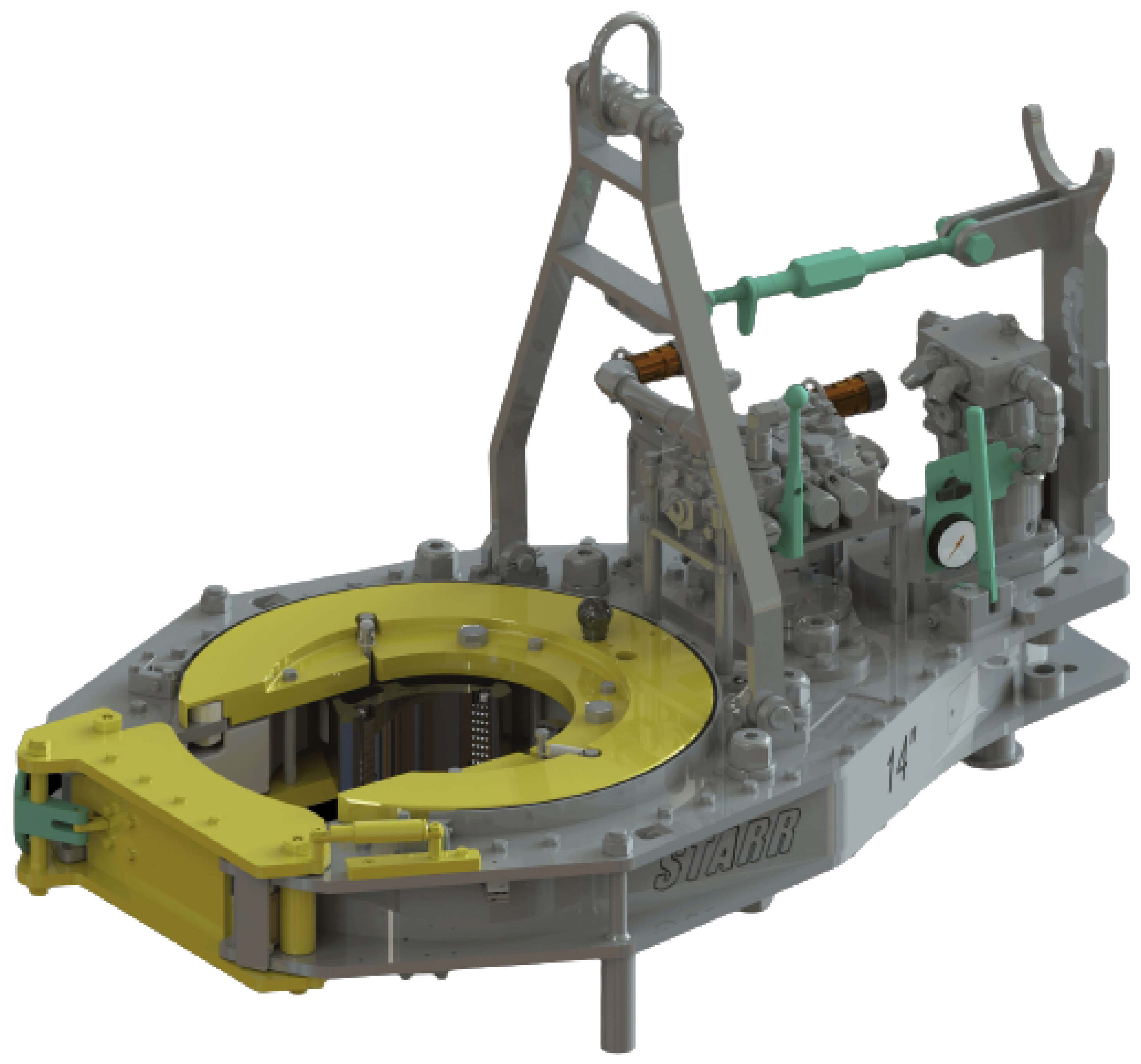
The HD31000 casing tong can handle tubulars as small as 10-3/4″ and as large as 31″ in diameter. Other sizes can be special-ordered. Tong can be mounted on either a CLINCHER® or a FARR® hydraulic backup. Available with McCoy’s patented WinCatt® data acquisition and torque control system for the make-up of tubular connections.
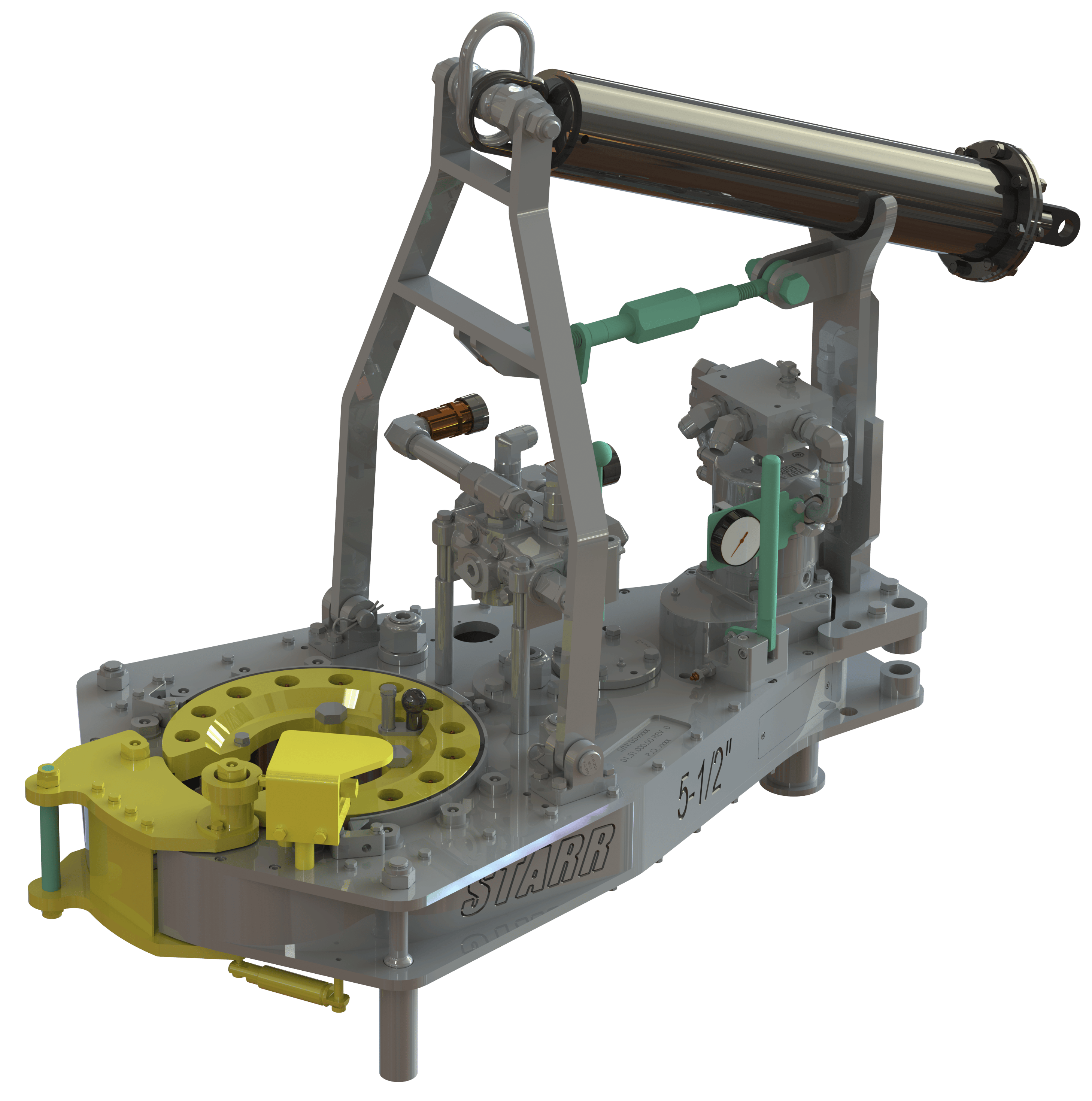
The new 7.25 HS HT-80 for Drill Pipe and High Torque Casing Tong takes on the toughest job with make-up and break-out of drill pipe, drill collars, and high torque casing with a maximum torque of 80,000 ft-lbs. The 7.25 HS HT-80 is available with a two-speed Hydra-Shift® motor coupled with a two-speed gear train providing (4) torque levels and (4) RPM speeds. The variable speeds can slowly or quickly spin tubular 2⅜ through 7¼ inch as necessary. Having exceptional gripping capabilities with rig dies for drill pipe or wrap-around dies that securely encompass the tubular limit potential for damage. The 7.25 HS HT-80 is also available with Eckel Pyramid Fine Tooth dies, or True-Grit dies. The 7.25 HS HT-80 is another of our tongs models that exceed the competition in its class.
For casing up to 22 inches, here"s a tong that has strong torquing ability and will handle pipe sizes down to 7 inch. The tong utilizes a two-speed motor and a two-speed gear train, allowing the operator to correctly adjust the tong for the optimum torque and RPM needed for the current application. Maximum torque for the 22 Hydra-Shift® is 80,000 ft-lb.
Tongs - Power - BJ sucker rod tong adopts advanced sucker rod or tubing technology and has a compact structure, high reliability and is safe and convenient to operate.
Tongs - Power - New Carter Tool Co. Inc., CT93R Hydraulic powered tubing tong. Complete with 2-3/8" to 3-1/2" jaw assemblies, standard motor, torque gauge assembly, pressure relief valve... More Info
Tongs - Power - New Carter Tool Co., Inc. 5-1/2" CTSX Hydraulic Tubing Tong with heavy case and cover; complete with rigid hanger assy., suspension spring assy., front end control assy.,... More Info
Tongs - Power - New Carter Tool Co. Inc. M-Series power sucker rod tongs, complete with spring hanger assy., gate assy., front end control assy., pressure gauge assy., two 90 degree XH s... More Info
Tongs - Power - New Carter Tool Co., Inc. 4-1/2" RSX Hydraulic Tubing Tong with heavy case and cover; complete with rigid hanger assy., suspension spring assy., front end control assy., ... More Info
Tongs - Power - D D 58-93-2-R Power Tubing Tong is smaller, lighter, and faster than the Foster 5893R. The D D 58-93-2-R Tong is capable of gripping tubulars from 1 5/16" to 7" o.d. More Info
Tongs - Power - FARR TONG MODEL KT 14,000 RINEER GA37 MOTOR, LIFT VALVE ASSEMBLY TORQUE CAPACITY: 50,000 FT/LB SIZE RANGE 4 1.2-14 WITH SAFETY DOOR MOST SIZES OF FARR POWER TONGS ARE IN ... More Info
Tongs - Power - FARR TONG MODEL KT20,000 STAFFA 080 MOTOR, LIFT VALVE ASSEMBLY TORQUE CAPACITY: 50,000 FT/LB SIZE RANGE: 7-20 MOST SIZES OF FARR POWER TONGS ARE IN HOUSTON, IN STOCK READ... More Info
Tongs - Power - FARR MODEL KT5500 HYDRAULIC TUBING TONG C/W 2 SPEED RINEER MOTOR, SIZE RANGE: 2-3/8 IN. - 5-1/2 IN. OD, TORQUE RTED: 18,700 FT/LB C/W SAFETY DOOR MOST SIZES OF FARR POWER... More Info
Tongs - Power - FARR TONG MODEL KT5500 TORQUE CAPACITY: 18000 FT/LB SIZE RANGE: 2 1/16-5 1/2 OD WITH SAFETY DOOR MOST SIZES OF FARR POWER TONGS ARE IN HOUSTON, IN STOCK READY FOR IMMEDIA... More Info
Tongs - Power - FARR TONG MODEL KT5500 5 1/2 IN. TONG TORQUE CAPACITY: 18,000 FT/LB SIZE RANGE: 2 1/16-5 1/2 IN. OD, RINEER 15-13 MOTOR, HIGH TORQUE CLINCHER BACKUP TRIPLE VALVE ASSEMBLY... More Info
Tongs - Power - FARR TONG MODEL KT7585 TORQUE CAPACITY: 25000 FT/LB SIZE RANGE: 2 1/16-8 5/8 OD WITH SAFETY DOOR MOST SIZES OF FARR POWER TONGS ARE IN HOUSTON, IN STOCK READY FOR IMMEDIA... More Info
Tongs - Power - FARR TONG MODEL KT7585 8 5/8 IN. TONG TORQUE CAPACITY 25,000 FT/LB SIZE RANGE: 2 1/16-8 5/8 IN. OD, RINEER 15-15 MOTOR CLINCHER BACKUP, TRIPLE VALVE MOST SIZES OF FARR PO... More Info
Tongs - Power - FARR TONG MODEL LW9625 TORQUE CAPACITY 12000 FT/LB SIZE RANGE 2 7/8 -9 5/8 OD WITH SAFETY DOOR MOST SIZES OF FARR POWER TONGS ARE IN HOUSTON, IN STOCK READY FOR IMMEDIATE... More Info
Tongs - Power - Farrs newest tubular connection tool offers a significantly reduced rig footprint, while continuing to deliver power & uncompromising reliability. The simple design drast... More Info
Tongs - Power - Farr Canada"s newest tubular connection tool offers a significantly reduced rig footprint, while continuing to deliver power and uncompromising reliability. The simple de... More Info

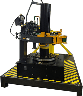
Our power tongs are built to last. With 1 motor options for the 6 1/4” hydraulic power tong, you crew can reach rated torque at 2500 psi. Which means, the tools can reach their rated torque dependably on ever single joint, every day.
With an investment like this, you don’t want one malfunctioning part to be the reason why your equipment isn’t performing. That’s why we build our tongs to be serviceable, high in quality. By using an ISO 9001:2015 quality system, we maintain a close eye on our products.

mccoyglobal.comCopyright © 2008 - 2012 McCoy Corporation. All rights reserved.Published by McCoy Corporation, Technical Publications Department14755 - 121A Avenue • Edmonton, AB, Canada, T5L 2T2 HD20-80K Tong
TONG MODEL REV DESCRIPTION 80-1503-1 0 Equipped with Rineer GA125 motor, motor valve, lift valve, safety door, and chain sling.
Technical Manual Section Contents iii HD20-80K Tong
WHEN RE-ASSEMBLING LOAD-BEARING devices (CHAIN SLINGS, RIGID SLINGS, BACKUP LEGS, ETC.) NOTE THAT THE ASSOCIATED FASTENERS MUST BE TIGHTENED TO THE CORRECT TORQUE SPECIFIED FOR THAT SIZE OF FASTENER (See section 3 - overhaul). Any threaded fastener in a load-bearing device must be secured with red or blue loctite™.
Technical Manual Section Contents v HD20-80K Tong Copyright © 2008 - 2012 McCoy Drilling & Completions, all rights reserved. This document is the property of McCoy Drilling & Completions and is supplied as reference information for users of our products. This document and the contents within are considered confidential infor- mation, not to be disclosed, copied, transmitted, transcribed in any form, or stored on any type of data storage media without the express written consent of McCoy Drilling & Completions. McCoy Drilling & Completions has made every effort to ensure the information contained in this document is accurate and current. This manual is intended to provide equipment operation and safety instructions for your equipment. However, McCoy Drilling & Completions does not warrant or guarantee that the information is either complete or accurate in every respect, and the user of the manual shall protect, indemnify, and hold harmless McCoy Drilling & Completions and all their directors, officers, employees, and agents from and against all liability for personal injury, death, or property damage resulting directly or indirectly from the use of the information contained in this manual. Observance of all descriptions, information and instructions set out in this manual is the full responsibility of the user. This manual is intended for guidance and informational purposes and must be used in association with adequate training and on-the-job supervision to provide safe and effective equipment use. It is the responsibility of the user to conform to all regulations and requirements issued by an authority or agency which may affect the operation, safety or equipment integrity, that may overrule the content of this documentation. The user will acknowledge and obey any general legal or other mandatory regulation in force relating to accident prevention, safety, and equipment integrity.
Summary Of Revisions Date Section Page Description Of Revision December 2008 N/A N/A Initial Release September 2009 2.8, 2.7 Added configuration 80-1503-2 (revised hyd. schematic) July 2011 2 2.10 Removed 22” jaw die kit from list of available jaws All All Updated branding to current standard 2.13 Revised subsection 2.F.1, Tong Rig-Up & Leveling, Suspension & Restraint 2.14 Replaced graphics, Tong Rig-Up 2 2.15 Inserted new subsection 2.G.1, Tong Operation, Operator Training 2.18 Inserted new subsection 2.G.4, Tong Operation, Shifting Gears 2.19 Inserted new Section 2.H, Making & Breaking ConnectionsThis page intentionally 3.1 Revised Section 3.A, General Maintenance Safety Practices left blank 3.1 Inserted new Section 3.C, Preventive Maintenance Practices 3.2-3.7 Replaced graphics Section 3.D, Lubrication 3.7 Replaced graphic, subsection 3.E.1, Brake Band Adjustment 3.9 Inserted new subsection 3.E.4, Shifter Detent Force Adjustment 3 3.10 Inserted new subsection 3.E.5, Safety Door Switch Adjustment Feb 2012 3.21 Inserted new Section 3.I, Power Tong Daily Inspection & Maintenance Checklist 3.23 Inserted new Section 3.J, Power Tong Monthly Inspection & Maintenance Checklist 3.26 Inserted new Section 3.K, Power Unit Daily Inspection & Maintenance Checklist 3.27 Inserted new Section 3.L, Tubular Connection Equipment De-Commissioning Checklist 3.28 Inserted new Section 3.M, Tubular Connection Equipment Re-Commissioning Checklist 4 4.1-4.6 Revised entire troubleshooting section Removed Section 5, De-Commissioning, Storage, & Re-Commissioning (replaced by 5.1 Sections 3.L & 3.M). Renumbered “Parts & Assemblies” as Section 5. 5 5.26 - 5.27 Replaced graphics & updated B.O.M., Motor & Motor Mount Assembly 5.32 - 5.33 Replaced graphics & updated B.O.M., Tong Door Assembly 5.34 - 5.35 Replaced graphics, Safety Door Components 6 6.1-6.6 Complete revision of torque measurement section
Technical Manual Section Contents viiHD20-80K Tong Table Of Contents Table Of Contents HD20-80K TongIntroduction.............................................................................................................................................................. Section 1 The information presented in this document will provide setup, operating, and maintenance instructions for Corporate Contact Information.........................................................................................................................1.1 your HD22-80K tong. Due to the wide variety of operating conditions, these instructions must be considered Equipment Specifications.................................................................................................................................1.2 Lubricant Specifications...................................................................................................................................1.4 guidelines rather than absolute operating procedures. It is the responsibility of the user to use these guidelinesOperation.................................................................................................................................................................. Section 2 together with an experienced manager to develop operating procedures that conform to all policies set forth by Sling & Load-Bearing Device Safety................................................................................................................2.1 the operating authority (ies). Major Component Identification.......................................................................................................................2.4 Hydraulic Schematic & Hydraulic Component Identification............................................................................2.7 Hydraulic Connections......................................................................................................................................2.10 IDENTIFICATION OF OF WARNINGS AND OTHER NOMENCLATURE OF Tong Jaw Availability & Installation..................................................................................................................2.11 IMPORTANCE USED IN THIS INSTALLATION GUIDE Tong Rig-up And Leveling................................................................................................................................2.13 Tong Operation.................................................................................................................................................2.15 Making & Breaking Connections......................................................................................................................2.19 McCoy Drilling & Completions uses three indicators to describe items of three degrees of importance. Cold Weather Operation...................................................................................................................................2.26Maintenance............................................................................................................................................................. Section 3 A HAZARD to operators or equipment is represented by an exclamation point within a red triangle. identifies items of the General Maintenance Safety Practices............................................................................................................3.1 highest importance. Failure to heed information identified by a HAZARD symbol may result in bodily injury, death, cata-Cleaning............................................................................................................................................................3.1 strophic equipment damage, or any combination of these. A HAZARD may also indicate the potential for dangerous envi- Preventive Maintenance Practices...................................................................................................................3.1 ronmental contamination.Lubrication........................................................................................................................................................3.2Adjustments......................................................................................................................................................3.7 Recommended Periodic Checks......................................................................................................................3.11 Overhaul Procedures........................................................................................................................................3.12 This identifies a HAZARD to operators or equipment Assembly Procedures.......................................................................................................................................3.14 Power Tong Daily Inspection & Maintenance Checklist...................................................................................3.21 Power Tong Monthly Inspection & Maintenance Checklist..............................................................................3.23 Power Unit Daily Inspection & Maintenance Checklist....................................................................................3.26 Tubular Connection Equipment De-commissioning Procedure.......................................................................3.27 A WARNING is represented by an exclamation point within an orange triangle, and contains information that will alert per- Tubular Connection Equipment Re-commissioning Procedure.......................................................................3.30 sonnel to a potential safety hazard that is not life-threatening. A WARNING may also serve to alert the user to informationTroubleshooting...................................................................................................................................................... Section 4 Tong Will Not Develop Sufficient Torque.........................................................................................................4.1 critical to the correct assembly or operation of the equipment in use. Failure Of Jaws To Grip Pipe............................................................................................................................4.3 Tong Running Too Slowly.................................................................................................................................4.4 Failure Or Difficulty Of Tong To Shift...............................................................................................................4.5 General Comments...........................................................................................................................................4.8 This identifies a WARNING to usersAssemblies And Parts ........................................................................................................................................... Section 5 Gear Train Layout.............................................................................................................................................5.2 Support Roller Assembly..................................................................................................................................5.4 Support Roller Assembly - Brake Band............................................................................................................5.6 Support Roller Assembly - Door Pivot..............................................................................................................5.8 A CAUTION is represented by an exclamation point within a yellow triangle and highlights information that may aid the user Rotary Idler With Gear Plate.............................................................................................................................5.10 Rotary Idler.......................................................................................................................................................5.12 during assembly or operation of your equipment. CAUTIONs are also used to ensure common errors are not made duringPinion Idler .......................................................................................................................................................5.14 assembly or operation of your equipment. Pinion Assembly...............................................................................................................................................5.16 Clutch Assembly...............................................................................................................................................5.18 Shifting Assembly.............................................................................................................................................5.20 Tong Body Assembly........................................................................................................................................5.22 This identifies a CAUTION to users Brake Band Assembly......................................................................................................................................5.24 Motor & Motor Mount........................................................................................................................................5.26 Hydraulic Assembly..........................................................................................................................................5.28 Cage Plate Assembly........................................................................................................................................5.30 Tong Door Assembly........................................................................................................................................5.32 Safety Door Components.................................................................................................................................5.34 Chain Sling Assembly.......................................................................................................................................5.36Torque Gauge Service Information....................................................................................................................... Section 6 Observance of the following is the full responsibility of the user: Basic Torque Measurement..............................................................................................................................6.1 Tension Load Cell.............................................................................................................................................6.3 • all descriptions, information and instructions set out in this manual Turn Counter Assembly & Mount......................................................................................................................6.4 Trouble Shooting...............................................................................................................................................6.5 • any regulation or requirement issued by an authority or agency which may influence operation, Periodic Inspection and Maintenance..............................................................................................................6.6 safety or integrity of the equipment that overrules the content of this document.Hydraulic Section.................................................................................................................................................... Section 7 Hydraulic Motor Information.............................................................................................................................7.1 • any legal or other mandatory regulation in force governing accident prevention or environmental Hydraulic Valve Information .............................................................................................................................7.15 protection.
viii Section Contents Technical Manual Technical Manual Section Contents ix Introduction HD20-80K Tong Congratulations on the purchase of your FARR® HD22-80K” tong. This unit will provide you with years of outstanding performance. Simple maintenance and care will extend its life and ensure years of excellent performance and reliability. The setup, operating, and maintenance instructions in this manual will assist you in giving your equipment the care it requires. Please carefully read the manual before installing and using your equipment. Replacement parts are readily available from McCoy Drilling & Completions | FARR in Edmonton, Alberta. Note that many parts are transferable between FARR® tongs and backups. Should you need replacement parts, or should you experience any difficulty not covered in this manual, please contact: McCoy Drilling & Completions | FARR 14755 121A Avenue Edmonton, Alberta Canada T5L 2T2 Phone: 780.453.3277 Fax: 780.455.2432 Sales Fax: 780.481.9246 Email Engineering: engFarr@mccoyglobal.com Email Sales: salesFarr@mccoyglobal.com Customer Care: customerCareFarr@mccoyglobal.com
Technical Manual Section Contents 1.1HD20-80K Tong Specifications Specifications HD20-80K Tong
Torque Table Pressure High Gear Low Gear PSI / MPa Lbs.-ft. Nm Lbs.-ft. Nm 1000 / 6.89 2200 2983 20000 27116 1500 / 10.34 4400 5966 40000 54233 2000 / 13.79 6560 8894 60100 81485 2500 / 17.24 8750 11863 80100 108600 MAXIMUM RATED TORQUE: 80000 LBS.-FT. / 108450 Nm
** These are ideal values. Actual achieved torque is highly dependant upon tong efficiency and final position of rotary gear when full torque load is reached. Maximum Hydraulic Requirements: 3000 PSI (20.68 MPa) 60 GPM / 227.1 LPM Maximum torque is only available in low gear 54-3/4” Length: 85-1/2 inches / 217.2 cm. Maximum Width: 54-3/4 inches / 139.1 cm. Height (Excluding Chain Sling): 36 inches / 91.44 cm. Space Required On Pipe: 8 inches / 20.32 cm. Torque arm length: 55 inches / 139.7 cm. (Pipe Centre Line to Load Cell Centre) Weight (Approximate): 4200 lb. / 1909 kg. Recommended Spring Hanger: Capacity 4500 lb. (2045 kg.) McCoy P/N 85-0106XXXH Jaws available (inches): See Pg. 2.10
1.2 Section Contents Technical Manual Technical Manual Section Contents 1.3HD20-80K Tong Specifications Setup & Operation HD20-80K Tong Use an EP synthetic grease that meets or exceeds the following specifications: Adequate setup and proper hydraulic connections are essential in ensuring reliable operation of your tong. For best results and long term reliability, read and obey the start-up instructions in this section. Thickener Lithium Complex NLGI consistency grade 2 DO NOT ACCESS ROTATING COMPONENTS UNLESS HYDRAULIC POWER SUPPLY HAS BEEN NLGI performance grade GC-LB DEACTIVATED OR ISOLATED. Penetration - ASTM D 217 (25°C [77°F] 265-295 minimum 0.1 mm) worked 60 strokes A CLEARLY IDENTIFIED REMOTE POWER PACK EMERGENCY STOP MUST BE INSTALLED IN Dropping point, °F[°C] - ASTM D2265 550 [288] minimum THE IMMEDIATE VICINITY OF THE TONG OPERATOR. High temperature life, hours - ASTM D 3527 160 minimum Oxidation stability, psi - ASTM D 942 (100 hr/300 hr) 0/3 A. SLING / LOAD BEARING DEVICE SAFETY Water washout, percent - ASTM D 1264 1.8 max Rust and corrosion - ASTM D 1743 pass The supplied Load-Bearing device (chain sling, rigid sling, spreader bar assem- Oil separation, percent loss - ASTM D 1742 1.1 max bly, frame, or any other device that bears the partial or total weight of the (24 hours, 25°C [77°F] equipment described in this manual) has been specified or designed to support Leakage, g lost - ASTM D 4290 1.0 max the equipment described in this DOCUMENT. Farr will not guarantee the ability Four ball wear test, mm scar - ASTM D 2266 0.40 max of the load-bearing device to support any other part, assembly or combina- Fretting wear, mg - ASTM D 4170 3.4 max tion of parts and assemblies, or any additions to the equipment described Four ball EP, kgf - ASTM D 2596 in this manual that add weight to the equipment, unless supplied by McCoy Weld point 400 minimum Load wear index 50 minimum Drilling & Completions. Timken OK load test, lbs - ASTM D 2509 50 McCoy Drilling & Completions DOES not guarantee the INTEGRITY of MODIFIED OR Low temperature torque, N*m - ASTM D 4693 1.3 max (-40°C [-40°F]) DAMAGED load-bearing deviceS, UNLESS THOSE MODIFICATIONS ARE PERFORMED BY LT-37 pumpability, g/min 360/7 McCoy Drilling & Completions. (60°F/0°F [16°C/-18°C]) McCoy Drilling & Completions recommends following an industry-accepted standard such as OSHA, ASME B30.9-2006, or manu- Copper corrosion - ASTM D 4048 1B facturer’s guidelines when performing any rigging and overhead lifting. Use by untrained persons is hazardous. Improper use will Disc brake wheel bearing specifications result in serious injury or death. Do not exceed rated capacity. Slings will fail if damaged, abused, misused, overused, or improperly Ford ESA-M1C 198A Yes maintained. Chrysler MS-3701 Yes • Only grade 80 or grade 100 alloy chain should be used for overhead lifting applications. Oil viscosity: 40°C [104°F], cSt 151 100°C [212°F], cSt 19.2 • Working Load Limit (WLL) is the maximum allowable load in pounds which may be applied to the load-bearing device, when the Flash point, °F[°C] - ASTM 92 450[232] device is new or in “as new” condition, and when the load is uniformly and directly applied. The WLL must never be exceeded. • Working Load Limit (WLL) is the maximum working load for a specific minimum sling angle, measured from the horizontal plane. The Working Load Limit is identified on the sling. Use a premium quality hydraulic fluid that meets or exceeds the following specifications: • The Working Load Limit or Design factor may be affected by wear, misuse, overloading, corrosion, deformation, intentional al- Typical Density (kg/m3) 878 terations, sharp corner cutting action and other use conditions. Viscosity - cSt @ 40 °C 68.8 • Shock loading and extraordinary conditions must be taken into account when selecting alloy chain slings. - cSt @ 100 °C 8.7 • See OSHA Regulation for Slings 1910.184, ANSI/ASME B30.9-”SLINGS”, ANSI/ASME B30.10-”HOOKS” and ANSI/AMSE Viscosity Index 97 B30.26 “RIGGING HARDWARE” for additional information. Pour Point °F [°C] -22 [-30] Flash Point °F [°C] 432 [222] Colour, ASTM 1.5 THE MINIMUM SLING ANGLE (THE ANGLE OF THE LEG OF THE SLING MEASURED FROM THE Neutralization Number 0.40 HORIZONTAL) MUST NEVER FALL LOWER THAN THE ANGLE SPECIFIED FOR THE SLING IN USE Rust Protection - Distilled Water No Rust - Sea Water No Rust Hydrolytic Stability - Cu Mass Loss, mg/cm2 0.04 Copper Corrosion Test 1A Filterability: Denison - Wet & Dry Pass Afnor - Wet & Dry Pass Cincinatti Milacron Spec Approved P69 Denison HF-0: Approved Denison P-46 Piston Pump: Pass Denison T6C Vane Pump: Pass Vickers 35VQ25 Vane Pump Test: Pass 104/105C Vane Pump Test: No Data Available Vane pump test total ring and vane wear, mg. <10 Oxidation Stability Turbine Oil Stability Test Life, hours 2500+ Rotary Bomb Oxidation Test, minutes 325 FZG Spur Gear Test, Failure Load Stage (FLS) 12
1.4 Section Contents Technical Manual Technical Manual Section Contents 2.1HD20-80K Tong Setup & Operation Setup & Operation HD20-80K Tong 1. Inspection Of Slings Test / Examination McCoy Drilling & Completions strongly recommends the following practices: Non -Destructive Examination Thorough Visual Suffix To Be Marked On A complete inspection of new load-bearing devices and attachments shall be performed by a qualified, designated person prior Time / Interval Lifting Tests1 (NDE) of Lifting Points E xamination Plate Attached To Unit to initial use. Each link and component shall be examined individually, taking care to expose and examine all surfaces including Initial Certification By Farr / the inner link surface. The sling shall be examined for conditions such as those listed in the removal criteria below. In addition, YES YES YES T Superior daily inspection of slings, fastenings and attachments shall be performed by a designated person. If damage or defects are found at either inspection, the damaged or defective component shall be quarantined from service until it can be properly repaired or Interval Not Exceeding 12 At the discretion of At the discretion of inspec- YES T or VN3 replaced. Months inspection body tion body
Removal Criteria: Interval Not Exceeding 60 At the discretion of YES YES T or VN Months inspection body A load-bearing device shall be removed from service if conditions such as the following are present: Following Substantial Repair • Missing or illegible sling identification. or Alteration4 YES YES YES T • Cracks or breaks • Evidence of tampering is seen - sling tag has been modified or obscured, or tamper-proof nuts are missing. 1. Lifting test as per S 7.3 BS EN 12079 or DNV 2.7-1 May 1995 • Signs of impact on load-bearing components, including spreader bars, lifting lugs, rigid slings & rigid sling weldments, and 2. T = Proof Test, non-destructive examination; VN = non destructive examination and visual examination; legs & leg mounts. V = visual examination. • Broken or damaged welds. 3. Dependant upon whether non-destructive examination has been carried out. • Excessive wear, nicks, or gouges. Refer to the chart below to ensure minimum thickness on chain links supplied is not be 4. For the purposes of this standard, a substantial repair or modification is defined as any repair and/or modification that has been below the values listed: carried out which may, in the opinion of the inspection body, affect the load-bearing elements of the container or lifting device, or elements that contribute directly to its structural integrity. Minimum Allowable Chain Link Thickness at Any Point IF MECHANICAL DAMAGE IS SEEN OR SUSPECTED ON A LOAD-BEARING DEVICE, OR IF THE Nominal Chain Size Minimum Thickness LOAD-BEARING DEVICE HAS BEEN OVERLOADED, IT MUST BE REMOVED FROM SERVICE AND Inches MM Inches MM QUARANTINED UNTIL RECERTIFIED 7/32 5.5 0.189 4.80 9/32 7 0.239 6.07 Written records of the most recent periodic inspection shall be maintained, and shall include the condition of the sling. 5/16 8 0.273 6.93 2. Proper Use Of Load-Bearing Devices 3/8 10 0.342 8.69 Whenever any load-bearing device is used, the following practices shall be observed. 1/2 13 0.443 11.26 • Load-bearing devices that are damaged or defective shall not be used. 5/8 16 0.546 13.87 • Slings shall not be shortened with knots or bolts or other makeshift devices. 3/4 20 0.687 17.45 • Sling legs shall not be kinked. • Load-bearing devices shall not be loaded in excess of their rated capacities. 7/8 22 0.750 19.05 • Slings shall be securely attached to their load. 1 26 0.887 22.53 • Load-bearing devices shall be protected from snagging, and shall not be further obstructed by any object. 1-1/4 32 1.091 27.71 • Suspended loads shall be kept clear of all obstruction. • All employees shall be kept clear of loads about to be lifted and of suspended loads. Refer To ASME B30.9 • Hands or fingers shall not be placed between the sling and its load while the sling is being tightened around the load. • Shock loading is prohibited. • Stretched, bent, twisted, or deformed chain links or components. • Do not stand directly under a load during lifting. • Evidence of heat damage. • Excessive pitting or corrosion. 3. Storage Of Load-Bearing Devices • Lack of ability of chain or components to hinge (articulate) freely. Proper storage of out-of-service load bearing devices is important to ensure full integrity of the device once it is returned to • Weld splatter. service. Farr recommends observing the following practices. • For hooks, removal criteria as stated in ASME B30.10 • Other conditions, including visible damage, that cause doubt as to the continued use of the sling. • Wipe off all excess grease. Use a solvent-based cleaner on rags to wipe all external surfaces to remove residual grease or hydraulic fluid. Once the outside surfaces have been de-greased, wipe all external surfaces with clean water to remove Inspect all lugs and fixing points for signs of elongation and/or bending, or for material build-up around the hole. Repair or residual solvent. replace components that appear distorted. Ensure all hardware is tight and in good condition. Replace missing hardware if necessary. All hardware must be free of rust and corrosion. • Farr recommends that an anti-corrosive agent such as Tectyl® 506 be applied to all external surfaces. Refer to manufacturer data sheets for proper application and safety information. Allow the anti-corrosive coating ample time to dry - refer to manu- Additional inspections shall be performed during sling use where service conditions warrant. Periodic inspection intervals shall facturer data sheets for drying times at room temperature. not exceed one year. The frequency of periodic inspections should be based on: • Store in a clean, dry location. When returning to service, note that a full inspection of the device must be performed. • Frequency of use of the load-bearing device. • Severity of service conditions • Nature of lifts being made • Experience gained on the service life of load-bearing devices used in similar circumstances. Guidelines for the interval are: ensure chains do not become entangled in any equipment superstructure when • Normal Service - yearly using chain slings to hoist equipment. • Severe Service - monthly to quarterly • Special Service - as recommended by a qualified person Units designed and manufactured in accordance with EN 12079 and DNV 2.7-1 should be tested and examined in accordance with the following schedule of examination and test. The user of the load-bearing device shall place a permanent placard or plate upon which the type and date of the last test shall be recorded. To avoid confusion, the plate shall not carry the date of the next test or examination, only the most recent.
2.2 Section Contents Technical Manual Technical Manual Section Contents 2.3HD20-80K Tong Setup & Operation Setup & Operation HD20-80K TongB. MAJOR COMPONENT IDENTIFICATION 6
2.4 Section Contents Technical Manual Technical Manual Section Contents 2.5HD20-80K Tong Setup & Operation Setup & Operation HD20-80K Tong C. HYDRAULIC SCHEMATICS & VALVE IDENTIFICATION Item Description Page 1 Chain Sling 2.4 MOTOR 2 Hydraulic Valve Assembly 2.4 12 MAKE UP 3 Torque Gauge Mounting Plate 2.4 DUMP VALVE 13 2 11 4 Tong Doors 2.4 OPTIONAL 14 1 5 Tong Door Cylinder 2.4 15 6 Backing Pin Assembly 2.5 P T 7 Cage Plate Assembly 2.5 8 Tong Jaws with Die Inserts 2.5 G LIFT 9 Brakeband 2.5 10 9 8 7 10 Door Adjustment Cam 2.5 11 Safety Door Switch Assembly 2.5 BACKUP 12 Hydraulic Motor 2.5 13 Motor Mount 2.5 14 Manual Shift Assembly 2.5 15 Inspection Panel 2.5
Item Description Part Number Page 1 Inlet Section 10-9016 2.8 2 Relief Valve 10-0062 2.8 3 Motor Valve Section 10-9014 2.8 4 Backup Valve Section (Optional) 10-9019 2.8 5 Lift Cylinder Valve Section (Optional) 10-9015 6 Outlet Section 10-0086 2.8 7 Flow Control Valve 08-9062 2.8 8 Pilot-To-Operate Cartridge Valve 08-1625 2.8 9 Safety Door Valve Block 101-0727 2.8 10 Safety Door Switch 08-0337 2.9 11 1/2” FNPT Check Valve 02-9228 2.8 12 Hydraulic Motor 87-0150 2.8 13 Dump Valve 08-9284 2.8 14 Dump Valve Body 08-9283 2.8 15 3000 psi Pressure Gauge 02-0245 2.8 16 Pressure Reducing Valve, PRJR-LAN (Optional) 08-1752 2.8 17 Valve Body, KCM (Optional) 08-1753 2.8
2.6 Section Contents Technical Manual Technical Manual Section Contents 2.7HD20-80K Tong Setup & Operation Setup & Operation HD20-80K Tong
2.8 Section Contents Technical Manual Technical Manual Section Contents 2.9HD20-80K Tong


 8613371530291