
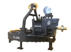
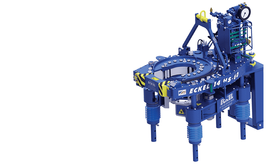
hydraulyc power tong 40 000 factory

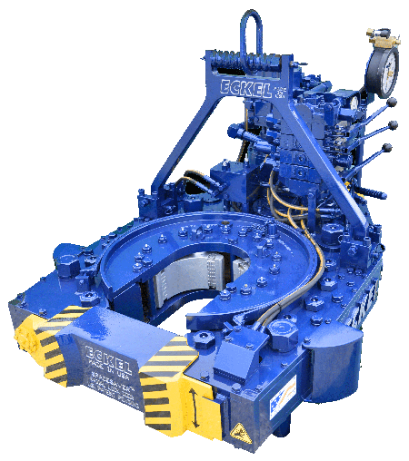
Casing Tongs provide make-up and break-out capabilities when running casing tubular in the drill hole to maintain well integrity. Casing tongs are available for various sizes from 5-1/2" to 36" and designed to handle high torque casing or lightweight casing. Available models: Standard, Hydra-Shift, High Torque, and Ultra High Torque with torques ranging from 15,000 ft-lbs up to 200,000 ft-lbs. Consistent operations between models reduce employee training.
In assembling a string of tubing for an oil well, a long series of pipe sections are screwed together, usually by means of a power tongs. Conventional power tongs have jaws with serrated faces that are designed to bite into the pipe surface. These jaws are usually cam operated, so that their closing force is roughly proportional to the tongs torque. Such an arrangement, however, is unsuitable for certain modern tube materials which are particularly soft. This is true for example, for some high chromium pipes designed for corrosion resistance rather than strength, and for fiber glass tubing now being developed. There are also pipes having protective coatings designed to protect the underlying material from corrosion by hydrogen sulfide and other subterranean chemicals. Some tubing costs on the order of one thousand dollars per foot, and a string is typically thousands of feet long. Plainly, it is critical not to damage tubing while making up a string, and to avoid any surface damage that could reduce service life.
Consequently, there is a need for power tongs whose jaws will not injure the surface of tubing and yet can deliver to the tubing adequate torque, which may be several thousands foot-pounds. The approach taken by this invention is to provide jaws actuated by hydraulic linear motors so that jaw pressure can be accurately controlled.
Hydraulically biased jaws on power tongs are known in the prior art; see, for example, U.S. Pat. Nos. 3,796,418, 3,921,473, 4,057,887 and No. 4,402,293. None of these however, provide means for independently controlling the jaw force.
It is therefore an object of this invention to construct a power tongs having jaws designed not to bite into the surface of pipe or tubing and yet able to transfer sufficient torque to the tubing.
Another object is to control jaw pressure independent of tongs torque. These and other objects will be apparent from the following description of a preferred embodiment of the invention.
The foregoing objects are met, according to this invention, by a power tongs having at least one hydraulically biased jaw, and means for controlling the hydraulic pressure delivered to the jaw. With this arrangement, smooth-faced jaws made of soft material can be used, and purely frictional engagement with the pipe surface suffices to make up the string.
As shown in FIGS. 1 and 2, an apparatus embodying the invention comprises a power tongs 10 including a motor 12 driven by hydraulic fluid or other medium. Means (not shown) are provided for manually or automatically controlling the tongs motor. The tongs motor 12 is connected through gearing, not shown, to a rotary head 14, to which the pipe gripping assembly 20 of the invention is attached. The gripping assembly comprises plural (preferably three) segments 22a, 22b, 22c equally spaced around a vertical axis corresponding to that of a pipe P that is to be torqued.
The gripping face 40 of each jaw is (FIG. 3) preferably smooth; that is, without teeth or other contours that might cut into and damage the pipe surface. This is particularly important for coated pipe, but as an alternative, the jaw surfaces may be "corrugated" as illustrated in FIG. 4. For fiberglass pipe, where surface damage can be tolerated, a serrated, knurled or toothed surface (FIG. 5) is preferred.
In operation, the tongs are brought, laterally, over a pipe joint P, FIG. 1, and the gripping assembly 20 is closed around the pipe by means of the latch 26. Air pressure from source 42 is then applied via fitting 44, whereupon the pump 46 generates hydraulic pressure within the cylinders 32, which pressure is limited by the setting of the pressure relief valve 52. The check valve 50 maintains the cylinder pressure after the air source is disconnected, whereafter there are no external hoses or other connections to the gripping device that would prevent it from rotating. The tongs are then activated, causing the gripping device and the pipe P to rotate with the rotary head until the desired torque is reached. Various torque limiters, such as those disclosed in U.S. Pat. Nos. 4,552,041 and 4,579,024, may be used to control the tongs, if desired.
To release the pipe P, the valve 54 is opened, allowing the pistons 34 to be retracted by their biasing springs as fluid escapes to the reservoir 48. The device may then be unlatched, and the tongs are then removed from the pipe.
The adjustability of the relief valve 52 enables one to control the actual clamping jaw force, independently of tongs torque. It is therefore possible, with this invention, to avoid excessive clamping pressures that could cause surface or structural damage to soft pipes. The service life of some of the most expensive tubing can thus be markedly prolonged. The pressure reaching cylinders 32 is limited by means of the adjustable pressure relief valve 52, which is set to a pressure that is a function of pipe material, size, makeup torque and possibly other factors. The upper pressure limit, for a given size jaw, is necessarily that pressure which would collapse or crush the pipe. However, the jaws may be made as long as desired; e.g., one foot long or more, so as to distribute jaw load over a greater surface area. As a result, by judicious design choice, any desired torque can be transferred to the pipe by the gripping assembly, without damaging the pipe surface.
With this invention, jaw forces are positively controlled and limitied, without regard to the tongs torque. This is in complete contrast to traditional cam-operated jaws, where jaw force is roughly proportional to tongs torque and is usually unknown in magnitude.
Various other modifications will occur to those of skill in the art, to create other uses for the invention. For example, the gripping device could be used in a (non-rotary) backup tongs. Also, high pressure water could be used in place of hydraulic fluid to drive the pistons 34, and such a modification would avoid the release of oil into the environment.
I am chairman of the board, president and chief executive officer of Eckel International, the largest global providers of innovative and high performance hydraulic power tongs for the oil and gas industry. I am a second-generation family member involved in manufacturing of tongs. In 1993, as Eckel’s president, I launched an initiative to further reach out to Russia’s oil & gas needs. Today, I am directly responsible for the overall operations of the company, sales, and new market initiatives.
Since 1958 Eckel has been supplying power tongs to the worlds O&G industries– but how long have you been doing business in Russia and what specific solutions do you offer to the region?
Eckel specializes in the development of hydraulic power tongs for make-up and break-out of tubulars, with over 60 years of tubular connection experience. Our industry leading technology advancements are in some respects, a reflection on the industry requirements and their needs. Eckel has been in the process of designing tongs that required very high torques, advanced safety features, and automation.
Eckel in-house heating provides quality tempered steel while observing strict industry standards. This process assures high quality and rugged durable parts within Eckel power tongs. Eckel has won a world-wide reputation of providing first-class products that deliver years of trouble free service. Our tongs have operated trouble free in the harsh cold conditions of Western and Eastern Siberia and in the Far Northern Regions. Eckel’s hydraulic power units have a proven track record in some of the harshest surroundings in Russia such as the extreme hot and cold conditions of Russian and offshore environments.
Eckel has provided more than 500 Hydraulic Power Tongs to oil and gas companies and drilling contractors in Russia. In Russia, as well as in many other countries, the use of Corrosion Resistant Alloys (CRA) chrome tubulars are becoming more popular. Eckel is an industry leader in this specialized field tubular connections offering a line CHROMEBOSS® tongs along with Eckel Non-Marking True Grit® dies. True Grit® Dies utilize Tungsten Carbide grit coating which provides many more points of contact on the surface of the tubular than standard Pyramid Fine Tooth dies provide. Penetration depth less than half the depth that is permissible by the American Petroleum Institute (API). Eckel’s True Grit® dies use a dense Tungsten Carbide coating that is a metal like substance which does not flake or sheer off the face of the die. Operational on-site tests have shown that the life time of Eckel True Grit® wrap-around dies is three times longer than competing abrasive powder coated dies. The above equipment and components have been working in Russia several years and proved its advantages.
The hydraulic power tong market is very competitive in Russia, with both local and international suppliers competing for business. Why should a drilling contractor or operator consider using Eckel equipment?
Eckel has over 60 years of experience in this area, and is known for quality and reliability. Many of these tong manufacturers use the old Foster and Hillman Kelly that are 30-year-old designs. Eckel is at the forefront of this industry designing tongs that can handle today’s premium high torque connections. Our tong designs evolved to incorporate additional safety features, automation, and performance. Our new 7.25 HSHT-80 Drill Pipe / Casing and 9-7/8 HS-60 Casing tongs incorporates many of these features.
Eckel has been the leader in development of tubular gripping such as the development of larger wrap-around type dies for many of its tong models. Depending on the application, Eckel offers a coarse tooth, pyramid fine tooth, and our proprietary True Grit dies. Dies are available as rig die style and for thinner wall tubulars where point loading is a concern we offer wrap-around dies. All Eckel equipment is produced at our Odessa, Texas USA manufacturing facilities (ISO 9001:2008 certified) that encompasses 140,663 square feet (13068 square meters) ensures the highest quality.
Coralina Engineering and Capital Equipment and Trading Corporation (CETCO) has operations in Azerbaijan, and their specialists are intensely involved in this territory. CETCO specialist are successfully making inroads in the Azerbaijan territory offering Eckel power tongs and power units. Additionally, CETCO provides training, classes, assistance, and local experience in all practical aspects of tong operation and maintenance. CETCO is very optimistic for doing business in Kazakhstan region. We are actively working in this region at improving our relationships with existing and new customers.
Eckel continues to improve tong designs, reliability, functionality, and reduce operational costs to comply with today’s oil and gas industry requirements, and anticipate tomorrows industry requirement. A few examples are:
• One of the latest design of a new backup with Wedge Drive Type Tri-Grip which is used on the most of tong models. The WD Tri-Grip is a high-performance backup with no compromises that is available for specific applications. The Wedge Drive Tri-Grip handles the most demanding torques that larger casing and drill pipes demand.
• A new 7.25 HS HT-80 tong, that was introduced in the last half of 2016 for drill pipes and high torque casing pipes. We believe the 7.25 HS HT-80 tong is an extremely needed product for the Russian market. We anticipate the specifications of the tong will be of great interest and welcome surprise for our customers.
• In 2017, Eckel will release a couple of new product designs. The new 9-7/8 HS-60 Casing Tong available the 1st Quarter of 2017 offers efficient and reliable high rotational performance for torque turn jobs. With these high torque ratings, the 9-7/8 HS-60 Casing Tong is capable of properly handling all premium grade tubulars within its size range.
Available in the 2nd Quarter of 2017, a new tong positioner “Tong Handler” that is permanently mounted within the rig which provides a cost effective, safer, and reduced labor-intensive method of maneuvering tongs to the rotary table area on the rig floor.
Russian is a very large and great country with lots of attention dedicated to the oil and gas industries onshore and offshore. Today’s challenge is to have equipment that meets the needs and requirements of oil and gas companies and drilling contractors. Since our first tong delivery in 1978 and now with the assistance of Capital Equipment and Trading Corporation and Coralina Engineering, we have developed a good relationship with many Russian customers and a growing list of new customers. Oil production is not so easy however; we believe that we can solve the most difficult problems facing the oil and gas industries. I have enjoyed visiting Russia many times for work and pleasure.
The present invention relates to open-head power tongs used in drilling operations, and more particularly, is directed to an improved means of actuating and deactuating the operation of the power tong drive means in response to the opened and closed positions of an access door.
As well known in the drilling industry, power tongs are employed in making-up and breaking-out operations of casings, tubings, rods, pipes and the like. More particularly, power tongs are used to grip and rotate lengths of drill pipe or the like to connect or join several lengths of pipe together to thereby form a drill string in a make-up operation, and in the alternative, to grip and rotate a length of drill pipe to disconnect it from the drill string in a break-out operation.
One type of power tong commonly used today is the open-head tong, such as the one shown and described in U.S. Pat. No. 4,060,014. The open-head tong has a bifrucated frame defining a central opening and a side opening communicating with the central opening for the passing therethrough of a drill pipe or the like. Due to the extreme costs of drilling, open-head tongs have become very popular, in that, they can easily and readily be moved into and out of an operative position when they are needed in the making up and breaking out of drill strings.
In operation, the open-head power tong exerts large rotational torques on the drill pipes, usually the larger the tong, the larger the torque output. Due to these large torque outputs and the resulting forces generated therefrom, the open-head tongs have been provided with an access door that bridges the gap between the bifrucated ends of the tong. The primary purpose of such an access door is to strengthen the tong structure so as to prevent, during the operation of the tong, the bifrucated ends from separating or springing apart, which not only results in damage to the tong, but could also inflict injury to the operating personnel. The access door, in addition to providing structural rigidity to the tong, also provides the operator with safety in bodily protecting him from the rotating pipe gripping and engaging jaws.
Such access doors perform very satisfactorily in providing structural rigidity to the tong and do provide protection to the operators from the rotating components of the tong when the door is properly latched in position during the make-up and break-out operations; however, in an effort to save time, operators have been known to operate the tong with the access door open, and in some instances, the operators have even removed the access door from the tong. Such operator"s carelessness not only causes costly structural damage to the tong, but also results in personal injury to the operator.
In U.S. Pat. No. 2,705,614 there is shown an open-head power tong having an automatic hydraulically powered access door, operably interconnected to the hydraulic cylinders that actuate the jaw gripping mechanism, which must be closed before the jaws can be actuated so as to rotate a drill pipe. Such door interlock mechanism has been specifically designed for the type of tong disclosed and is not readily adaptable to other types of power tongs, such as the one shown in the above-mentioned U.S. Pat. No. 4,060,014. Further, the hydraulic circuitry that is involved with such a powered access door is not only complicated, having expensive components, but is also, costly to maintain and repair. Still further, such door interlock mechanism does not provide adequate safety to an operator, in that, although the operator is protected from the pipe gripping and engaging mechanism when the door is closed, he is also subjected to the risk of having the power operated door being automatically swung into him as it is being closed, thus, creating a potentially dangerous and unsafe condition under which the operator must work.
The present invention obviates the problems experienced with access doors and disadvantages associated with the prior art door-interlock mechanisms by providing, as one of its principle objects, an improved door-interlock mechanism for an open-head power tong that ensures the access door is in a closed position before the tong can be operated, thereby preventing possible structural damage to the tong from operating the tong with the door open, as well as, preventing personal injury to the operators by protecting them from the various rotating components of the tong.
Another object of the present invention is to provide a door-interlock mechanism for an open-head power tong that is simple in structure and adaptable to all types of open-head power tongs.
Accordingly, the present invention, sets forth in an open-head power tong having an access door mounted on the tong and moveable between opened and closed positions, an improved door-interlock mechanism that includes means for controlling the operation of the tong in response to the opened and closed position of the door. More particularly, the control means preferably includes a pneumatic contact valve interconnected with a pneumatically piloted diverter valve operably associated with the power means of the tong such that the power means is placed in either an operative or inoperative condition in response to respective closed and opened positions of the door. Specifically, the pneumatic contact valve is so positioned in the vicinity of the side opening that the door, in its closed position, engages the contact valve thereby actuating the diverter valve to permit operation of the power means, and when, the door is moved from its closed position out of engagement with the contact valve, the contact valve causes the diverter valve to deactuate the power means, thus stopping the operation thereof.
FIG. 1 is a top plan view of an open-head power tong incorporating the improved door-interlock mechanism of the present invention with the access door being in its closed position in engagement with the contact valve which actuates the diverter valve.
FIG. 2 is a diagrammatic fragmentary view of the power tong showing the side edge portion of the access door with the door latch removed and with the contact valve being in disengagement with the door which is partly open.
Referring to the drawings, and particularly, to FIG. 1, there is shown, for illustration purposes only, an open-head power tong, being generally indicated by the numeral 10, incorporating the principles of the present invention. The tong illustrated in FIG. 1 is of the type shown and described in U.S. Pat. No. 4,060,014, and thus, for the sake of brevity, since the tong itself forms no part of this invention, only a brief description of the tong will follow.
Briefly, as best seen in FIG. 1, the power tong 10 is comprised of a bifrucated frame structure 12 defining a central drill pipe receiving opening, and a side opening that communicates to the central opening for laterally passing a drill pipe therewithin. Rotatably supported within the frame structure 12 is a pipe engaging and gripping means that includes jaws 14 that swing into and out of the central opening for gripping and rotating a drill pipe disposed within the central opening during make-up and break-out operations of a drill string. The pipe engaging and gripping means with its associated jaws 14 are rotatably driven through a suitable drive train (not shown) by power means such as the hydraulic motor 16 which receives fluid under pressure from a suitable hydraulic pump (not shown) and through a hydraulic control valve 17. The valve 17 is conventional, being moveable between three spool positions; one position being such that the fluid drives the motor in a forward clockwise direction, another position being such that the hydraulic fluid drives the motor in a reverse counterclockwise direction, and the third position being a neutral position wherein fluid passes through the valve to the return line that returns the fluid to a reservoir (not shown) for recirculation thereof.
Also supported on the frame structure 12 is an access door 18, adapted to span or bridge the access opening defined between the bifrucated end portions so as to provide structural rigidity to the power tong 10, as well as, to protect the operator from the various moving components, such as the jaws 14. One end of the access door 18 is hinged to an end of one of the frame bifrucations by a pivot pin 20 whereas the free end of the door is provided with a self-latching arm 22 that engages a latch member 24 mounted on the other bifrucation so as to positively latch the door when it is closed. The door and the door latching mechanism are of the type shown and described in a pending U.S. application, bearing U.S. Ser. No. 791,752; filed Apr. 28, 1977; and entitled TONG LOCKING MECHANISM. The door and the latching mechanism forms no part of this invention and thus a further description will not be given.
To ensure that the tong 10 is only operated when the door 18 is closed, closing the access opening, the tong 10 is provided with an interlock mechanism which basically includes a contact valve 26, engageable by the door 18, and a hydraulic diverter valve 28, operably associated with the hydraulic motor 16 so as to permit flow of hydraulic fluid to the motor, or, in the alternative position, to bypass the flow of hydraulic fluid around the motor.
Now turning to FIG. 3 which schematically represents the various operating components as well as the hydraulic and pneumatic circuitry associated therewith, the operation of the door interlock will be further described. First, it should be noted that both the hydraulic source and the pneumatic source are fully operating with respective fluids being under pressure in inlet lines, the access door 18 being closed, engaged with the actuating arm of the contact valve 26, the piloted diverter valve 28 being detented so as to pass the flow of hydraulic fluid around the motor 16, and with the hydraulic spool control valve 17 being in its neutral position such that fluid passes directly therethrough to the reservoir tank via inlet line 34, passageway 36, return line 38. Thus, as the spool valve 17 is shifted to its forward drive position, hydraulic fluid passes from the inlet line 34, through passageway 40, to line 42, through passageway 44 (of diverter valve 28), to line 46 which directs fluid into the left-hand side of the motor 16, and then via lines 48,49 to passageway 50 of valve 18 which is internally connected to the hydraulic return line 38. If the spool valve 17 is shifted in an opposite direction so as to reverse the direction of the motor 16, fluid flows via line 34, through passageway 52 to line 49 and line 48 to the right side of the motor 16, and then returns via lines 46, passageway 44, line 42 to passageway 54 which is internally connected to return line 38. It can be thus seen that when pressure is applied on the diverter valve 28, it is so positioned to pass hydraulic fluid either to one or the other sides of the motor 16 to thereby drive the rotating components of the tong 10 in either forward or reverse directions depending on the forward or reverse positions of the control valve 17. However, when the pneumatic pressure is relieved from the diverter valve 28, the internal spring forces the valve to the right, thus changing the flow path of the hydraulic fluid so as to bypass the motor 16. In such pressure relief position of the diverter valve 28, the fluid flow path is via lines 49,58, passageway 56 and line 42, thereby bypassing the flow of fluid to the motor 16. Since the flow of fluid through line 46 is blocked, no fluid passes to the motor 16, thus rendering it inoperative.
It can be understood from the foregoing that the described interlock-mechanism controls the operation of the hydraulic motor 16, and thus the operation of the tong 10, in response to the open and closed positions of the access door 18, such that the tong 10 can only be operated with the access door 18 in its closed position, and thereby eliminating the possibility of structural damage to the tong from operating same with the door open, as well as, providing safety to the operator from exposure to the various operating components of the tong.
I am chairman of the board, president and chief executive officer of Eckel International, the largest global providers of innovative and high performance hydraulic power tongs for the oil and gas industry. I am a second-generation family member involved in manufacturing of tongs. In 1993, as Eckel’s president, I launched an initiative to further reach out to Russia’s oil & gas needs. Today, I am directly responsible for the overall operations of the company, sales, and new market initiatives.
Since 1958 Eckel has been supplying power tongs to the worlds O&G industries– but how long have you been doing business in Russia and what specific solutions do you offer to the region?
Eckel specializes in the development of hydraulic power tongs for make-up and break-out of tubulars, with over 60 years of tubular connection experience. Our industry leading technology advancements are in some respects, a reflection on the industry requirements and their needs. Eckel has been in the process of designing tongs that required very high torques, advanced safety features, and automation.
Eckel in-house heating provides quality tempered steel while observing strict industry standards. This process assures high quality and rugged durable parts within Eckel power tongs. Eckel has won a world-wide reputation of providing first-class products that deliver years of trouble free service. Our tongs have operated trouble free in the harsh cold conditions of Western and Eastern Siberia and in the Far Northern Regions. Eckel’s hydraulic power units have a proven track record in some of the harshest surroundings in Russia such as the extreme hot and cold conditions of Russian and offshore environments.
Eckel has provided more than 500 Hydraulic Power Tongs to oil and gas companies and drilling contractors in Russia. In Russia, as well as in many other countries, the use of Corrosion Resistant Alloys (CRA) chrome tubulars are becoming more popular. Eckel is an industry leader in this specialized field tubular connections offering a line CHROMEBOSS® tongs along with Eckel Non-Marking True Grit® dies. True Grit® Dies utilize Tungsten Carbide grit coating which provides many more points of contact on the surface of the tubular than standard Pyramid Fine Tooth dies provide. Penetration depth less than half the depth that is permissible by the American Petroleum Institute (API). Eckel’s True Grit® dies use a dense Tungsten Carbide coating that is a metal like substance which does not flake or sheer off the face of the die. Operational on-site tests have shown that the life time of Eckel True Grit® wrap-around dies is three times longer than competing abrasive powder coated dies. The above equipment and components have been working in Russia several years and proved its advantages.
The hydraulic power tong market is very competitive in Russia, with both local and international suppliers competing for business. Why should a drilling contractor or operator consider using Eckel equipment?
Eckel has over 60 years of experience in this area, and is known for quality and reliability. Many of these tong manufacturers use the old Foster and Hillman Kelly that are 30-year-old designs. Eckel is at the forefront of this industry designing tongs that can handle today’s premium high torque connections. Our tong designs evolved to incorporate additional safety features, automation, and performance. Our new 7.25 HSHT-80 Drill Pipe / Casing and 9-7/8 HS-60 Casing tongs incorporates many of these features.
Eckel has been the leader in development of tubular gripping such as the development of larger wrap-around type dies for many of its tong models. Depending on the application, Eckel offers a coarse tooth, pyramid fine tooth, and our proprietary True Grit dies. Dies are available as rig die style and for thinner wall tubulars where point loading is a concern we offer wrap-around dies. All Eckel equipment is produced at our Odessa, Texas USA manufacturing facilities (ISO 9001:2008 certified) that encompasses 140,663 square feet (13068 square meters) ensures the highest quality.
Coralina Engineering and Capital Equipment and Trading Corporation (CETCO) has operations in Azerbaijan, and their specialists are intensely involved in this territory. CETCO specialist are successfully making inroads in the Azerbaijan territory offering Eckel power tongs and power units. Additionally, CETCO provides training, classes, assistance, and local experience in all practical aspects of tong operation and maintenance. CETCO is very optimistic for doing business in Kazakhstan region. We are actively working in this region at improving our relationships with existing and new customers.
Eckel continues to improve tong designs, reliability, functionality, and reduce operational costs to comply with today’s oil and gas industry requirements, and anticipate tomorrows industry requirement. A few examples are:
• One of the latest design of a new backup with Wedge Drive Type Tri-Grip which is used on the most of tong models. The WD Tri-Grip is a high-performance backup with no compromises that is available for specific applications. The Wedge Drive Tri-Grip handles the most demanding torques that larger casing and drill pipes demand.
• A new 7.25 HS HT-80 tong, that was introduced in the last half of 2016 for drill pipes and high torque casing pipes. We believe the 7.25 HS HT-80 tong is an extremely needed product for the Russian market. We anticipate the specifications of the tong will be of great interest and welcome surprise for our customers.
• In 2017, Eckel will release a couple of new product designs. The new 9-7/8 HS-60 Casing Tong available the 1st Quarter of 2017 offers efficient and reliable high rotational performance for torque turn jobs. With these high torque ratings, the 9-7/8 HS-60 Casing Tong is capable of properly handling all premium grade tubulars within its size range.
Available in the 2nd Quarter of 2017, a new tong positioner “Tong Handler” that is permanently mounted within the rig which provides a cost effective, safer, and reduced labor-intensive method of maneuvering tongs to the rotary table area on the rig floor.
Russian is a very large and great country with lots of attention dedicated to the oil and gas industries onshore and offshore. Today’s challenge is to have equipment that meets the needs and requirements of oil and gas companies and drilling contractors. Since our first tong delivery in 1978 and now with the assistance of Capital Equipment and Trading Corporation and Coralina Engineering, we have developed a good relationship with many Russian customers and a growing list of new customers. Oil production is not so easy however; we believe that we can solve the most difficult problems facing the oil and gas industries. I have enjoyed visiting Russia many times for work and pleasure.

The bucking unit has been designed to make and break screwed connections with high torques. The unit is a combination of a KOLLER hydraulic vice 220 kN and a hydraulic operated chain tong.
For the basic unit without electronic data logger, no electrical supply is required. Both, the hydraulic vice and the tong are supplied by pressure air driven hydraulic power packs.
One type of open head tongs having non-rotatable gripping elements which has been utilized heretofore included a pair of diametrically opposed tong dies which were biased into engagement with the work piece. This tong quite often provided gripping on only a 180° quadrant of the work piece or provided gripping at only two locations thereby: increasing the potential of the work piece being dislodged from the tong grip; increasing the potential of damage of the work piece because of overstressing at either or both of the points of contact with the work piece; and/or necessitating a plurality of different tong dies or manual die adjustments over a very small range of work piece diameters. These problems are particularly acute when the tone is used in oil field applications, for example as a backup tong where the range of applied torques may exceed 40,000 Ft-lb. and the tong may be expected to handle a wide range of drill pipe diameters such as 41/4 to 71/4 inches.
An alternative to the two tong die system utilizes more than two dies and a latching door. This alternative system would aid in the problems of the work becoming dislodged and would provide more than two point contact; however, the mechanical configurations of such prior systems limited the range of work diameters which could be utilized.
By means of the present invention which includes an open tong which is structured to generally freely receive the work piece therewithin and thereafter engage, independently of a latching door, the work piece at a plurality of locations no more than 120° apart, the hereinabove mentioned problems are generally alleviated. Furthermore, the tong of the present invention includes means for camming engagement of the tong dies with the work piece in a manner that all tong dies engage the work piece simultaneously and equal forces are applied thereto. Still further, a lost motion arrangement with the tong jaws of the present invention provides an even greater range of work diameters which may be used with a single tong constructed according to the principles of the present invention.
FIG. 1 is a schematic illustration of power and backup tong assembly which incorporates a backup tong constructed in accordance with the principles of the present invention;
FIG. 2 is a plan view, with the top plate removed of a backup tong as illustrated in FIG. 1 and constructed in accordance with the principles of the present invention;
FIG. 1 is a schematic illustration of power and backup tong assembly 10 comprising a suitable power tong 12 which carries a backup tong 14 of the present invention. Power tong 12 is any suitable construction and as shown supports backup tong 14 therefrom by means of releasable side support assemblies 16 and a rear assembly 18 which communicates between backup tong 14 adjacent the rearward end thereof and a suitable torque transmitting assembly 20. Torque transmitting assembly 20 extends downwardly from power tong 12 adjacent the rearward end thereof. As is known with a unit such as assembly 10 the backup tong 14 is carried by power tong 12 to oppose the rotational reaction force of the power tong 12 when making up or breaking out of a threaded joint of pipe. The backup tong 14 prevents the free spinning of the lower portion of the pipe and eliminates the real need of a backup cable which presents a myriad of problems not the least of which is the bending of the pipe being coupled or uncoupled. In operation the tongs 12 and 14 grip adjacent pieces of pipe or collars being coupled or uncoupled.
Backup tong 14 comprises an elongated generally hollow main casing 22; a jaw assembly 24 received within casing 22; and a hydraulic or pneumatic actuator means or piston assembly 26 which is received within casing 22 and is selectively operable to extend and retract respective elements of jaw assembly 24 to engage and disengage the work.
Jaw assembly 24 comprises a plurality of spaced tong jaws or jaw crank arms which are pivotally carried within casing 22 adjacent the periphery 32 and as illustrated in FIG. 2 include forward tong jaws or jaw crank arms 38 and 40 and a rear tong jaw or jaw crank arm 41. As indicated in the drawings jaw crank arms 38, 40 and 41 are shown in solid in their open position and shown in phantom in their respective closed positions.
Crank arm 38 comprises: an elongated tong die carrying portion 42 which carries a tong die 116 at the free end thereof; a suitable pivot portion or connecting sleeve 46, formed in any suitable manner, for example as a through bore or as a hollow cylindrical vertically extending pivot sleeve rigidly secured to portion 42 or integrally formed therewith adjacent the opposite end thereof; and a biforcated link arm connecting portion 48 which is rigidly secured to sleeve 46 and extends rearwardly therefrom generally along an axis extending in the direction of the longitudinal extent of portion 42. Connecting portion 48 includes a pair of spaced connecting members 50 having vertically aligned bores 52 therethrough which are utilized for the pivotal connection to a link arm as described hereinafter.
Crank arm 40 is similar in construction to arm 38 described hereinabove and comprises: an elongated tong die carrying portion 54 which carries a tong die 116 at the free end thereof; a pivot portion 46 rigidly secured to or integrally formed with portion 54 adjacent the other end of arm 40; and a link connecting portion 56 which communicates with portion 46 and extends therefrom along an axis which intersects, at an obtuse angle, an axis drawn through the longitudinal extent of portion 54. Link connecting portion 56 is shown as having a vertical bore 58 therethrough for pivotal connection to a link arm as described hereinafter. Crank arm 41 is substantially similar in operative description to crank arm 40; however; for ease of description hereafter the tong die carrying portion, link connecting portion and the vertical bore through the link connecting portion are respectively assigned differing reference numerals 60, 62 and 64.
Crank arm 40 is pivotally carried within main casing 22 by a vertically extending pivot assembly 66 which is positioned in casing 22 outwardly adjacent one side of the straight portion of opening 32. Pivot assembly 66 comprises: vertically aligned bores 68 which extend through top and bottom walls 28 and 30; a vertically extending pivot pin 70 which is received through the pivot portion 46 of crank arm 40; and top and bottom end retainer caps 72 which have a downwardly open depression 74 therewithin to retain the respective axial ends of pivot pin 70. End caps 72 are secured to casing 22 in any suitable manner and are shown in FIG. 4 as having a portion thereof received within the interior of respective bores 68.
Crank arms 38 and 41 are pivotally carried within main casing 22 in a manner identical to that discussed above with reference to crank arm 40. The pivot assembly 66 for crank arm 38 is positioned on casing 22 outwardly adjacent the side of the straight portion of opening 32 directly opposite from crank arm 40. The pivot assembly 66 for crank arm 41 is positioned on casing 22 rearwardly adjacent the inner closed end of opening 32.
Piston assembly 26 is positioned within a rearward portion of casing 22 and comprises a double acting piston assembly 76 having a piston rod 78 reciprocably driven by means of a suitable fluid under pressure being alternatively supplied through suitable fluid power inlets 80 located at respective axial ends of assembly 76. To extend the piston rod 78 fluid under pressure is supplied to the rear inlet 80 and the forward inlet 80 is directed to tank or atmosphere. Conversely to retract the piston rod 78 fluid under pressure is supplied to the forward inlet 80 and the rear inlet 80 is directed to tank or atmosphere. The rear end of piston assembly 26 is carried adjacent a rear end portion of casing 22 and the forward end thereof is suitably pivotally connected to a link arm 82.
An elongated bent link arm 98 communicates between crank arms 40 and 41 with one end of link arm 98 being pivotally connected to crank arm 40 with a pivot assembly 100 at bore 56 and the other end of link arm 98 being pivotally connected to crank arm 41 with pivot assembly 101 at bore 64. Link arm 98 and crank arms 40 and 41 communicate with link arm 82 at lost motion connection 102. Lost motion connection 102 comprises a pair of vertically spaced ears 104 which extend outwardly from rear crank arm 41 and include vertically aligned bores 106 therethrough. The lost motion link portion 90 is received between ears 104 and the slot 91 is aligned with bores 106 in a manner that a vertically extending pivot pin 108 is received through the bores 106 and slot 91. The pivot pin 108 is retained in assembled position in any suitable manner, for example cotter pin 110.
Link arm 98 and crank arms 40 and 41 are continuously urged toward the open or retracted position illustrated in FIG. 2 by biasing means, shown as an elongated spring 112. Spring 112 is received within casing 22 and has one end thereof releasably secured to a vertical pin 114 which extends rigidly between top and bottom walls 28 and 30. The other end of spring 112 is releasably secured to pivot assembly 101.
With a backup tong 14 as described hereinabove and the jaw assembly 24 in an open position as shown in FIG. 2, wherein all elements of arms 38, 40 and 41 and of link arms 82 and 98 are within the casing 22 and retracted from opening 32, the work or pipe W is easily received within opening 32 with no fear of contacting or damaging the elements of jaw assembly 24 during initial set up.
It is noted that in certain instances, for example where arms 38, 40 and 41 are changed to accommodate a range of pipes different from the range accommodated by the illustrated embodiment, that the outermost end of the arm 38 may extend slightly into the opening 32 in the retracted position. Nevertheless this slight obstruction, for example 1 inch will still allow easy insertion of a large range of work diameters within the opening 32.
After reception of the work W with opening 32 the piston assembly 26 is energized to extend the piston rod 78. The piston rod 78 pushes on link arm 82 causing arm 82 to move forward which in turn results in pivot assembly 88 moving outward. The outward movement of piston assembly 88 causes forward crank arm 38 to rotate counterclockwise about the respective pivot assembly 66 therefor. During this initial movement and rotation of forward crank arm 38, crank arms 40 and 41 and link 98 remain biased into their retracted positions and do not move by virtue of the lost motion arrangement existing between the lost motion connection 102 and the slot 91 in the lost motion link portion 90. During this initial movement and rotation, pivot pin 110 of the lost motion connection 102 slides rearwardly along slot 91 until the instant the pin 110 contacts the rear end of slot 91 adjacent the free end of the lost motion link portion 90. At this instant crank arm 38 has rotated to the position indicated by the reference 92 and arm 38 and arms 40 and 41 are all in a fixed relationship to each other and have identical angular relationship (generally 120° apart) to the center of the backup tong which is indicated with an X placed within opening 32. Prior to this time crank arm 38 did not have an equal angular relationship with arms 40 and 41 because of the necessity of allowing a clearance opening 32 for the insertion of the work.
With pivot pin 110 contacting the end of slot 91 the extension of piston rod 78 continues thereby continuing the rotation of crank arm 38 about the respective pivot assembly therefore while simultaneously pushing on crank arm 41 and causing the counterclockwise rotation thereof about the respective pivot assembly 66 therefor. This rotation of crank arm 41 results in the rearward and outward movement of pivot assembly 101 which in turn pulls on link arm 98 to cause the counterclockwise rotation of crank arm 40 about the respective pivot assembly 66 therefor. This rotation of crank arms 38, 40 and 41 continues in unison until the replaceable arcuate tong dies 116 carried at the free ends of such arms engage the work W. At this point it is noted that although spring 112 is tensioned and opposing the piston assembly 26, the resulting spring biasing force is insignificant.
With the tong dies now engaging the work or pipe W, the power tong 12 rotates a joint of pipe clockwise, when making up a threaded connection, and the pipe W is restricted from rotation by the crank arms 38, 40 and 41 as the respective dies 116 therefor firmly engage and cam into the pipe W at respective angular positioning of approximately 120°. Once the dies 116 firmly engage the pipe W bearing rotated, the jaw assembly 24 becomes self-energizing. When the casing 22 of the backup tong 14 attempts to rotate, as it will when the backup tong 14 resists the pipe rotation, the resulting torque moment is transmitted to the frame of the power tong 12 by the force reaction. Although very high torque levels may be encountered in makeup or break down (i.e. 40,000 to 100,000 ft-lb), the power tong 10 and backup tong 14 acts as an integral unit and no external restrains are theoretically required.
After the threaded joint has been made up to the proper torque requirement, the pressure fluid is then applied to the forward end of piston assembly 26 causing the piston rod 78 to retract. This release of the directly applied closing force on crank arm 41, coupled with the continuous opening bias erected by the spring 112 will result in the rapid repositioning of crank arms 40 and 41 and link arm into the open position illustrated in FIG. 2. The retraction of piston rod 78 is continued until portion 42 is pivoted into the fully open position of FIG. 2.
The jaw assembly 24 is unidirectional. Accordingly, suitable means are provided to make backup tong 14 invertible in a manner that an operator may select the proper position to oppose the power tong (i.e. make up or break down position). Although not shown in detail a system for inverting tong 14 is generally illustrated wherein release of side support assemblies 16 would result in the forward portion of tong 14 dropping down by rotation about a first transverse axis at rear assembly 18 and thereafter the tong 14 is inverted by rotation about another transverse axis at rear assembly 18 which is perpendicular to the first transverse axis. The side support assemblies are then reconnected on the inverted tong 14 and the tong would now be operable for pipe break down rather than make up as was described hereinbefore.
It is to be understood that the invention herein is directed to a tong having an improved jaw system and modifications to the preferred embodiment described hereinbefore may be made by one skilled in the art without departing from the scope of the invention which is only defined by the claims appended hereto, for example: it is possible to utilize more than three jaws; if desired a manual system may be used for extension or retraction of jaw assembly 24 rather than the illustrated piston assembly 26 or as an override used in conjunction with the assembly 26; a pivotal gate may be provided to selectively close off opening 32; the jaw, link and pivot assembly configurations may vary; other sets of jaws may be provided to accommodate additional ranges of pipe diameter (i.e. one set of jaws for pipe diameter 41/2 inches to 53/8 inches and another set for pipe diameter 51/2 to 71/4 inches); a tong constructed in accordance with the principles of the present invention may be used as a primary tong rather than a backup tong as described; and the like.
The S10,000 basic rig, 30,000# cap., consists of a 40′ telescoping mast and 140′ per minute line speed at 10,000# single line. Also, as standard equipment is a 60 gallon oil reservoir, tandem hydro pump, 225′ of 9/16″ XIPS main line cable, 7 ton swivel safety bearing hook, fail safe brake, hydro control and variable speed engine control. Painted Standard SEMCO White. SEE OPTION LIST.
The S12,000H basic rig is 36,000# cap., consists of a 44′ hydraulic telescoping mast and 140′ per minute line speed at 12,000# single line. Also, standard equipment is a 72 gallon oil reservoir, tandem hydro pump, 225′ of 9/16″ XIPS main line cable, 11 ton swivel safety bearing hook, fail safe brake, hydro controls, and variable speed engine control. Painted White (S12,000 Old Style “A” Frame option has the 6,000# tail out winch, the S12H does not have the tail out winch also the S12H cannot have the power arm).


 8613371530291