
model xq114 6yb hydraulic hydraulic hydraulic hydraulic power tong pricelist
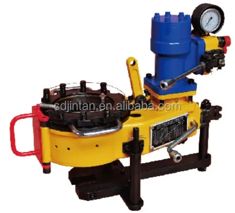
Model XQ114/6YB(4 1/2") hydraulic power tong is an open type power tong for the making up and breaking out of tubing in well services. This product has the following features:
2 CONTENTS Ⅰ. SUMMARY 1 Ⅱ. SEPCIFICATION 1 Ⅲ. INSTALLATION 1 Ⅳ. OPERATION 2 Ⅴ. MAINTENANCE & LUBRICATION 2 Ⅵ. ORDINARY PROBLEMS AND TROUBLESHOOTING GUIDE 3 Ⅶ. TABLE OF JAW AND DIES 4 Ⅷ. TORQUE CHART 4 Ⅸ. TABLE OF PARTS AND DRAWINGS 5 Fig.1 Shell 5 Fig.2 Brake mechanism and reset mechanism 6 Fig.3 Idle shaft 7 Fig.4 Hanging rod assembly 8 Fig.5 Power input shaft 9 Fig.6 Shifting mechanism assembly 10 Fig.7 Centralizing mechanism 11 Fig.8 Tong head assembly 12 Fig.9 Duplex gear shaft 13 Fig.10 Hydraulic motor 14 Fig.11 Safety door assembly 15 Fig.12 Lift assembly 16 Fig.13 Backup tong head 17 Fig.14 Backup tong tail 19 Fig.15 Fore guide rod assembly 21 Fig.16 Back guide rod assembly 22 Fig.17 Hand control valve 23
3 Ⅰ. SUMMARY Model XQ114/6YB(4 1/2") hydraulic power tong is an open type power tong for the making up and breaking out of tubing in well services. This product has the following features: 1,The tong is made up of master tong and backup tong, the master tong has a high and low gear train, the tong is compact, light and efficient. 2, The master tong and backup hydraulics operate on valve banks independent of each other. 3,The tong has incorporated a new system of disc brake to hold the jaws to connection more effectively. 4,Makeup and breakout are made easy with a simple turn to the reset knob on the tong and backup. 5,The backup has been supplied with quick coupling hoses and connections for quick and easy installation for jobs where you need a backup and the backup can be removed in seconds for jobs that a backup is not required. Ⅱ. SEPCIFICATION 1, Application:Tubing:73mm-114mm (2 7/8"to 4 1/2") 2, High gear rated torque:1.5 kn.m (1106 ft.lbs) 3, Low gear rated torque:6 kn.m (4425 ft.lbs) 4, high gear max rotation speed:85 RPM 5, Low gear max rotation speed:20 RPM 6, Opening of tong head:118 mm 7, Overall dimension (L W H): mm 8, Weight:220 kg(485lbs) 9, Rated system pressure:1595 Psi 10, Max oil supply:100 L/ min Ⅲ. INSTALLATION A, Hanging: Connect lift with tong hanging rod and hang the tong on the derrick of workover rig, the hanging point is 15 m above ground and the hanging should be in free condition. The distance between the tong center and the center of the well is recommended to be 0.5m. The hanging height is proper when the backup tong could rightly grip the tubing collar. B, Level: Adjust the screw (Z6-58)on the tong hanger to level the tong and backup, this should be done to ensure proper gripping of the jaws. C, Back guy: Tie one end of back guy on derrick and the other end on back guide seat of power tong, back guy should be capable of bearing a load of 20 KN, when power tong is in make up position, the back guy should be at right angle to the tong and on the opposite side of operator who operates the control handles, this insures a safe operation. D, Pressure hoses: Connect hoses from the hydraulic power source to the control valve bank of the power tong. The inlet and the outlet hoses can t be misconnected. 1
4 Ⅳ. OPERATION Making up tubing can be spun first in high gear range, final torques must be done in the low gear range. A PSI chart is provided to convert PSI to FT.LBS torque. Break out must be started in low gear range, once the joint has been loosened, the final brake out can be done in the high gear range. 1, Make-up: After aligning the opening tong head with the backup, turn the reset knobs of each (Z6-49) and (B6-3) switch the arrow to point the direction of make-up. Locate the tong and backup on to the tubing. The backup should be engaged to lock onto the tubing first. Once the backup jaws have been locked on, commence make up with the tong. After the tubing is made up, reserve rotation of the tong to align the opening of the tong with the tubing. Once this is accomplished, reverse the backup to align the opening of the backup to the tubing. The tong can be moved off the tubing. Confirm proper make up torques required from your tubing supplier. 2. Break out Aligning the opening tong head with the backup, turn the reset knobs of each(z6-49) and (B6-3) and switch them to point the direction of break out, then push it towards the tubing. Making the jaws of the tong and the backup line up squarely on tubing. Engage the backup first locking onto the tubing. Commence break out with the tong. Initial break out should always be done in low gear range. Once break out is accomplished. The joint may be spun off in high gear. To come off the couplings reverse the rotation of the tong and backup slowly to align the opening of the tong and backup to the tubing. The tong can now be removed off the tubing. 3. Replacing jaws. Tong and backup insert jaws slide into the tong heads easily. When you dismount jaws, turn tong head firstly, make the stop screw on the jaw set bracket expose from the opening tong head, loose the stop screw, then you can take out the jaws from the center of tong head. Mounting operation procedure is just on the contrary. Ⅴ. MAINTENANCE & LUBRICATION It is suggested that a regular maintenance program be established, to assure dependable operation of the tubing tong. The following recommendations concerning cleaning, lubrication, and cleaning will enhance the life expectancy of the tong and assure safety to operating personnel. A, Cleaning The tong should be thoroughly cleaned with a good petroleum base cleaning agent, after each job, prior to storage, it is recommended that periodically the motor and valve assembly be removed, along with the top tong plate, so that guides, rollers and gears can be properly cleaned. B, lubrication A good grade of multipurpose bearing lubricant which is compatible with expected ambient temperature is recommended along with the following lubrication procedures, at the completion of each job prior to storage. 1, All grease fittings should have 2 to 5 shots of grease after each job. 2, Rotary gear cam surface should be well greased applying with a rag or a brush. 3, Cage plates/rings should be coated with grease both through the grease nipples and coated on the rings. 4, Gears can be greased by removed the side inspection cover plate and apply grease directly to the gear teeth. 2
5 Ⅵ. ORDINARY PROBLEMS AND TROUBLESHOOTING GUIDE TROUBLE CAUSE. REMEDY A, JAWS ARE SELECTED IMPROPERLY. CHANGE JAWS TO PROPER SIZE. TONG DIE SLIPPAGE B, GRIT/MUD ETC.FILL DIE GROOVES. CLEAN THE DIES. C, TONG DIES WORN. CHANGE TO NEW DIES. D, DISC BRAKE LOOSE. TIGHTEN DISC BRAKE SPRINGS. E, TONG IS NOT LEVEL. ADJUST LEVELING SCREW ON RIGID SLING. CAGE PLATES ON TONG OR BACKUP WILL NO ALIGHT WITH OPENING BODY RETAINING PINS (Z-69) (B6-5) ARE NOT WRAPPED BY RESET KNOB SHAFT TURN RESET KNOBS(Z6-49) and (B6-3) 180º THEN RESET. BACKUP SLIPPAGE TONG HYDRAULIC PRESSURE DROP/ OR HYDRAULIC LEAKS. CHECK VALVE PRESSURE IN INCREASE SYSTEM PRESSURE/ REPLACE VALVE SEALS IF REQUIRED. ENGAGING A GEAR IS NOT FIRM AND IT DISENGAGE EASILY LOCKING EFFORT IS A LITTLE SMALL. ADD ADJUSTING SHIM AND INCREASE THE PRESSURE OF SPRING. 3
6 Ⅶ. TABLE OF JAW AND DIES The table of jaw specification Tong-jaw size Backup-jaw size Tubing Purchasing Purchasing size Mark Mark Remark number number B6-31(1) grip main body 2-3/8" Z6-79(1) B6-31(2) grip collar B6-31(3) grip (EU) collar 2-7/8" Z6-79(2) B6-31(4) grip collar B6-31(2) grip main body 3-1/2" Z6-79(3) B6-31(5) grip collar B6-31(4) grip main body 4" Z6-79(4) 105 B6-31(5) grip small drill pipe 4-1/2" Z6-79(5) B6-31(5) grip main body B6-31(6) grip collar Remark: The customer could select to purchase above jaws according to the requirement. Dies specification Tubing size Dies for tong and backup Purchasing number Mark 2-3/8" 2-7/8" Z6-73(1) /2" 4-1/2" Z6-73(2) Ⅷ. TORQUE CHART PSI VS FT.LBS. (4-1/2 TONG) PSI LOW HIGH
8 Fig. 2 Brake mechanism and reset mechanism Item Purchasing number Part number Part name QTY 1 Z6-50 GB Cylinder pin Z6-49 XYQ3B.Z.1-7 Reset knob 1 3 Z6-44 XYQ6B.Z-23 Brake disc 1 4 Z6-46 XYQ6B.Z-24 Friction disc 2 5 Z6-45 GB68-85 Slotted countersunk screw M Z6-25 GB70-85 Hexagon socket head cap screw M Z6-48 XYQ6B.Z-26 Brake steel plate 1 8 Z6-47 XYQ6B.Z-25 Connecting plate 1 9 Z6-66 GB70-85 Hexagon socket head cap screw M Z6-43 XYQ6B.Z-22 Tong cover 1 11 Z6-54 GB Hex bolt M Z6-28 XYQ3B.Z-6 Brake spring Z6-53 GB65-85 Slotted cylinder head screw M Z6-52 XYQ3B.B-20 Spring 2 15 Z6-117 GB Steel ball Z6-128 XYQ3B.Z.1-20 Locating seat 1 17 Z6-21 GB68-85 Slotted countersunk screw M Z6-51 XYQ6B.Z-27 Reset knob shaft 1 6
11 Fig.5 Power input shaft Item Purchasing number Part number Part name QTY 1 Z6-114 XYQ6B.Z-57 Motor liner ring 1 2 Z6-115 GB Deep groove ball bearing Z6-111 XYQ6B.Z-55 Power input shaft 1 4 Z6-36 XYQ6B.Z-19 Centralizing washer 2 5 Z6-17 GB Roller needle Ф Z6-16 XYQ6B.Z-8 Shifting gear 1 7 Z6-19 XYQ6B.Z-10 Spline gear 1 8 Z6-18 XYQ6B.Z-9 Inner gear sleeve 1 9 Z6-20 XYQ6B.Z.1 Clutch gear assembly 1 10 Z6-24 XYQ6B.Z-14 Bearing disc 1 11 Z6-22 GB Deep groove ball bearing
14 Fig. 8 Tong head assembly Item Purchasing number Part number Part name QTY 1 Z6-70 XYQ6B.Z-34 Open gear cover 1 2 Z6-81 XYQ6B.Z-32 Stop screw M Z6-71 XYQ6B.Z-35 Jaw set bracket 1 4 Z6-80 XYQ6B.Z-43 Ramp 4 5 Z6-72 XYQ6B.Z-36 Open gear 1 6 Z6-1 GB70-85 Hexagon socket head cap screw M
16 Fig. 10 Hydraulic motor Item Purchasing number Part number Part name QTY 1 Z6-113 GB70-85 Hexagon socket head cap screw M Z6-31 GB93-87 Spring washer Z6-112 XYQ6B.Z-56 Motor connecting seat 1 4 Z6-114 XYQ6B.Z-57 Motor sleeve 1 5 Z6-35 Hydraulic motor BM-D Z6-131 XYQ3C.Z.5 Hand control valve 1 14
17 Fig. 11 Safety door assembly Item Purchasing number Part number Part name QTY 1 Z6-119 XYQ6B.Z-62 Rotation shaft(1) 1 2 Z6-122 GB71-85 Slotted cone end fastening screw M Z6-120 XYQ6B.Z.5 Safety door 1 4 Z6-132 GB93-87 Spring washer Z6-124 XYQ6B.Z-66(2) Rotation shaft 1 6 Z6-124 XYQ6B.Z-65 Pull spring 1 7 Z6-44 XYQ6B.Z-23 Brake disc 1 8 Z6-43 XYQ6B.Z-22 Tong cover 1 9 Z6-4 XYQ6B.Z-2 Shell 1 15
20 Item Purchasing number Part number Part name QTY 1 3C1-70 GB70-85 Hexagon socket head cap screw M B6-64 XYQ1.8Z-24 Tong head handle 2 3 B6-1 XYQ6B.B-1 Backup tong head cover 1 4 B6-6 XYQ6B.B-5 Backup tong jaw set bracket 1 5 B6-25 XYQ6B.Z-44 Set screw 2 6 B6-24 XYQ6B.B-13 Ramp 4 7 B6-22 GB70-85 Hexagon socket head cap screw M B6-23 GB93-87 Spring washer B6-21 XYQ6B.B-12 Backup fore support seat 2 10 B6-7 XYQ6B.B-6 Backup tong head main body 1 11 B6-20 GB70-85 Hexagon socket head cap screw M B6-67 GB70-85 Hexagon socket head cap screw M B6-63 GB70-85 Hexagon socket head cap screw M B6-2 GB Cylinder pin B6-3 XYQ3B.B-2 Backup reset knob 1 16 B6-16 XYQ3B.B-20 Spring 2 17 B6-17 GB Steel ball B6-65 XYQ6B.B-25 Centralizing shaft 1 19 B6-66 XYQ6B.B-26 Centralizing roller 1 20 B6-4 XYQ6B.B-3 Backup reset knob shaft 1 21 B6-5 XYQ6B.B-4 Retainer pin 1 22 B6-32 XYQ6B.Z-37 Die 2 23 B6-28 GB71-85 Slotted cone end fastening screw M H 4 24 B6-30 XYQ6B.Z-40 Roller shaft 2 25 B6-27 XYQ6B.Z-38 Die retainer pin 8 26 B6-26 XYQ3B.Z.1-18 Spring 8 27 B6-29 XYQ6B.Z-41 Roller 2 28 B6-31 XYQ6B.B-14 ( 1 ) - (5) Jaw set 2 pcs for each kind 18
22 Item Purchasing number Part number Part name QTY 1 B6-10 GB70-85 Hexagon socket head cap screw M B6-13 GB70-85 Hexagon socket head cap screw M B6-12 XYQ6B.B-9 Gear cover 1 4 B6-9 XYQ6B.Z-20 Setting plate 1 5 B6-8 XYQ6B.B-7 Rotation shaft 1 6 B6-11 XYQ6B.B-8 Duplex gear 1 7 B6-68 GB Parallel key B6-15 XYQ6B.B-10 Tong tail oil cylinder 1 9 B6-34 GB Double head bolt M B6-33 GB93-87 Spring washer B6-47 GB Hex head nut M B6-37 XYQ6B.B-15C Cylinder cover 2 13 B6-71 GB O ring B6-72 GB RingA B6-73 XYQ6B.B-22A Plunger 2 16 B6-74 XYQ6B.B-27 Support ring 2 17 B6-75 GB O ring B6-38 XYQ6B.B-16B Oil cylinder cover 2 19 B6-35 GB70-85 Hexagon socket head cap screw M B6-13 XYQ3B.B-9 Oil passing bolt 4 21 B6-14 GB O ring B6-18 XYQ3B.B-12 Longer adapter 1 23 B6-43 JB/ZQ Hose adapter 10Ⅱ B6-45 XYQ6B.B-18 Joint 2 25 B6-95 XYQ6B.B-11 Hex head bolt M B6-96 GB93-87 Spring washer B6-62 XYQ6B.B-24(1) Tong tail seat 1 28 B6-41 XYQ6B.B-17C Rack plunger 1 29 B6-97 GB Hex nut M
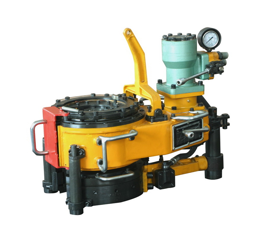
Multi-joint torque control power tong is a new pattern hydraulic power tong which is based on the XQ series hydraulic power tong and equipped with multi-joint torque control system, and the number of the patent is 201010138634.5. It adopts advanced steering mechanism, tubing clamping technology and multi-joint torque control system, which has the characteristic of easy structure, reliable performance, long working life, stable operation, low noise, flexible operation, safe working, it is an ideal equipment in oil field for repairing well.
A set of power tong is composed of master tong and hydraulic power backup tong. When operating the hand-control directional overflow combination valves on the master tong, the backup tong and master tong can work synchronously and coordinate with each other flexibly.
It can equip bilateral sequence control apparatus that is specialized in tubing tong according the need, so it can realize that the backup tong clamps the tubing tong in advance of master tong and it is more reliable and safer to make up or break out tubing. The number of patent is 2010101421692.
The power tong is equipped with multi-joint torque control system. And the number of the patent is 201010138634.5. You can set several optimum torque ratings one time according to request for making up different specifications of tubing.

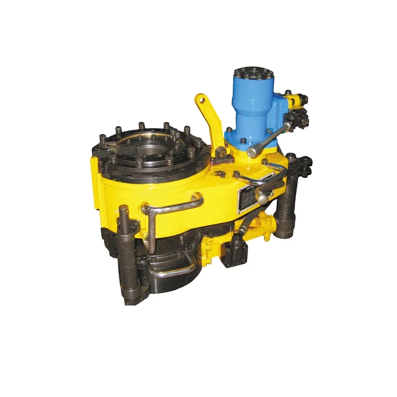
Model XQ114/6B(4 1/2") hydraulic power tong is an open type power tong for the making up and breaking out of tubing in well services. This product has the following features:

Make : BOMCO Model/Type : DM4.5/10.5-L1 Size Range : Power catwalk for casing, tubing capacity:2 3/8″- 24″
Hydraulic elevator, casing, tubing, DP, DC capacity:2 3/8″-9 5/8″Blow out preventers :
c) Mast and Substructure certified and meets API Yes Specification 4F, RP 4Gd) Telescoping mast with independently driven mast raising Yes system. Mast locking pins accessible without having to climb the mast.e) Complete Mast fitted with vapor tight, fluorescent lighting Yes,In system, certified to be used in accordance with accordance hazardous zones (as defined by API RP 505 with API RP Recommended Practice for Classification of Locations for 505 , API RP Electrical Installations at Petroleum Facilities Classified as 500, GB 3836, Class 1, Zone 0, Zone 1, and Zone 2, 1st edition January IEC60079 1997 including errata August 1998) and PDO Specification SP-2037 for drilling & workover operations & wireline operations / perforating operations with 12 m long lubricator rigged up at drill floor level. Supplied lighting good for ambient temperature rating of 55 deg Celsius and meets Temperature classification code T3 or superior. Meet requirements listed in C6 Technical specifications and Attachment 1 to Appendix 2 – Equipment list.f) Substructure fitted with heavy duty, vapor tight, Yes fluorescent lighting system, certified to be used in accordance with hazardous zones (as defined by API RP 505 Recommended Practice for Classification of Locations for Electrical Installations at Petroleum Facilities Classified as Class 1, Zone 0, Zone 1, and Zone 2, 1st edition January 1997 including errata August 1998) and PDO Specification SP-2037. Supplied lighting good for ambient temperature rating of 55 deg Celsius and meets Temperature classification code T3 or superior. Meet requirements listed in C6 Technical specifications and Attachment 1 to Appendix 2 – Equipment list.g) Maximum height with mast down when rig moving of 11 Yes m without removing monkey board.h) Both mast and substructure shall be wheel mounted for yes fast moving and are capable of moving Mast Up/Mast Down while TDS remain in Mast.i) Substructure capable of straddling all PDO standard Yes cellars (Type 1,2, 3, 4 & 5 Company standard cellars – reference to diagrams in C6) with adequate separation between substructure beams and/or wheels so as to clear the external walls of the cellar and avoid loading of the walls of the cellar.j) Setback capacity of at least 3000 m 5” 29 kg/m drill pipe Yes + BHA of 45,000 daN.k) Substructure capacity of at least the combined loads Yes listed in B.1.0 j) and B.4.0 d)l) Clear height below rotary beams /BOP trolley (not drill Yes floor elevation) from ground level of at least 6 m.m) In case, rig design requires Casing stabbing board, it Yes shall be adjustable for range 2 & 3 tubulars. Stabbing board to have automatic stops, "dead man" controls, anchor point outside the board and be certified as a man riding device. Stabbing board meets all requirements listed in C6 Technical Specifications and Attachment 1 to Appendix 2 – Equipment list.n) Power Catwalk with pipe bins and racks to deliver tubular Yes from catwalk level to drill floor suitable for handling single/double stands of tubings, drill pipe and collars 3 1/2” – 20”o) Drill floor c/w dog house, flush set-back area, anti-slip Yes surface i.e mats over the entire working area, two access ways c/w swing gate (none alongside i.e parallel to the "V" door ramp), a gate to close off the top of the ramp, pad-eye for a lower logging sheave rated to 20,000 daN, recessed into the rig-floor and the recess provided with a cover. Toeboards for all rig floor railings. Hand rails to meet OSHA specifications and API RP 54. Suitable size for safe working.p) Driller cabin (Dog House) to have acoustic enclosure, Yes climate controlled, designed to allow for ergonomics and for clear view on rig floor and monkey board, certified to be used in accordance with hazardous zones as defied by API RP 505 Recommended Practice for Classification of Locations for Electrical Installations at Petroleum Facilities Classified as Class 1, Zone 0, Zone 1, and Zone 2, 1st edition January 1997 including errata August 1998) and PDO Specification SP-2037. All windows on the cabin must be fitted with shatterproof safety glass and wiper. Positive pressure system or equivalent if required. Suitable size for safe working. 2x rig floor winch, 1x man riding winch, 1x monkey Yes board winch. – All winches to be fitted with cable guard – Pneumatic winches to be fitted with silencers - Rig floor winch of 2.5 tonne capacity, fitted with automatic spooling device - Rotating barrel swivelq) The man riding system (winch, cable, sheaves etc) shall be engineered to be one compatible unit complete with : - Limited max pull to 150 kg
s) A certified padeye to suspend upper logging sheave Yes during logging, rated to 20,000 daN, for operations through the top drive and another padeye for rigging up secondary retention. Suitable for wireline overstripping /cut and thread operation.t) Anchor point to suspend blocks during slip/cut. Block Yes must be suspended by special dedicated sling from crown block and not via fast line clamp in front of drawworks.u) Drainage system and drip pan to contain fluids spilled on Yes rig floor.v) Provision of a portable independent diesel powered Yes hydraulic power unit capable of lowering and raising mast without switching on the main rig powerw) Mast height shall be such that with the TDS (including Yes saver sub) and the stand of drillpipe one metre above the rotary table, the clearance between the travelling block and crown block shall be a minimum of 3.0 mx) Monkey board fingers have individual secondary Yes retention.
a) Rated to provide at least a hoisting speed of 0.38m/sec Yes (75 ft/min) based on the weight of a vertical string of 3000m of 5” 29 kg/m drill pipe in air plus bottom hole assembly weighing 45,000 daN in air (assuming efficiency factor of 0.8). Copy of calculations to be submitted by Contractor for verification.b) Safety device to prevent the travelling block colliding with Yes the crown block and the rig floor. Company requires the installation of an anti-collision system over and above the crown-o-matic.c) AC Motor Parking Brake, Eaton or a conventional Eddy- Yes current type auxiliary brake with independent battery backup. Brakes backup batteries should be located in a safe area or equipped and certified as suitable for use in hazardous area (as defined by API RP 505 Recommended Practice for Classification of Locations for Electrical Installations at Petroleum Facilities Classified as Class 1, Zone 0, Zone 1, and Zone 2, 1st edition January 1997 including errata August 1998) and PDO Specifications SP-2037. All brake and clutch linings to be asbestos free.d) Electric or hydraulic auxiliary brake. In case of an electric Yes hydraulic (Eddy-current) auxiliary brake with independent battery auxiliary backup. Size of Elmago shall be as per OEM brake recommendation compatable with rig HP rating. Submit Efficiency calculation proving sufficient for maximum hookload of the rig from OEM.e) If applicable, closed loop brake water cooling system for Yes drawworks and auxiliary brake rated for 55 deg C ambient temperatures with flow, temperature and fluid level alarms.f) Electrical motors coupled to draw-works meet Yes requirements listed in C6 Technical Specifications and Attachment 1 to Appendix 2 – Equipment list.g) In case disk brakes are provided as an alternative to AC Yes motors brakes, a minimum of 6 disk brakes are required (including both drawworks drum flanges) , out of which at least 2 disk brakes must function as parking brakes . The emergency braking system button shall activate at least 4 out of the 6 disk brakes.h) Company Option: Autodriller or ROP Optimizer system Yes, equipped Autodriller is able to control drilling parameters (Constant WOB and with auto driller able to torque/differential pressure). Wildcat ADS or equivalent control constant WOB & pressure
f) Swivel with 6 5/8” Reg left hand pin connection, Yes integral with TDS.g) Fitting for wireline entry on top of Gooseneck. The Yes wireline entry top should have a 1502 WECO connection with a minimum drift ID of 76.2 mm. NPT or other fine threads are not acceptable.h) Drilling line drum to be powered and shaded. Yes
f) In the drilling mode sufficient power must be available to Yescontrol and power simultaneously 2 (two) mud pumps, plustop drive, plus all auxiliaries (including but not limited to riglighting, all shale shakers, all mud tank agitators and mudtank transfer pumps) all at full load, plus the drawworks athalf load.Copy of power load calculations to be submitted forverification.
h)3 Emergency shutdown switches to shutdown AC/DC power Yessystem located at the driller"s position and in the toolpusher’soffice and outside of the engine room (accessible withoutopening the door of the engine room). These emergencyshutdown switches will result in a total black-out andshutdown ALL engines on the rig Site. When the emergencyshutdown’s switch is activated, air intake valves on dieselengines should be automatically closing. ESD switches shall becapable of operating the air shut-off valves on the engines.
i) Provision of stable auxiliary power supply for all Yes Company"s or Company"s Other Contractor(s) equipment (including but not limited to mud logging unit, MWD unit, centrifuge and mud cooler), when required.j) A rig service air system with air compressors, receivers Yes and dryers to adequately power all pneumatic rig equipment.k) Emergency generator available at rig Site to provide power Yes to rig Site offices and accommodation primarily during rig moves when main rig power plant is switched off or not available c/w switch-over provision. It shall be connected to MCC bus and air compressor, trip tank pump, transfer pumps, mud agitators, rig floor HPU, BOP control unit to be tied and into and be able to concurrently run from the emergency generator.l) Portable engine driven air compressor of sufficient Yes capacity to power the BOP control unit, start the engines, choke operation etc.m) AC-VFD room floor covered with electrical resistance Yesrubber mat
Continuous output power available (kW/HP) each generator : 1523kW or 429-470 kWOutput volts / Frequency (Volts / Hz) : 600V/60Hz
Compliance Yes/No?C.2.0 Company Requirementsa) Sufficient power available to supply camp at peak Yes demand.b) Option to connect to a Company power grid 230/460 230/460 Volts/60Hz Volts / 50Hz. Contractor Specifications
c) Power Slips Air or Hydraulically operated power slips to Yes handle DP size in use. Not weight activated. Company preference is power slips or Backsaver manufactured by Blohm & Voss,or Varcod) Drill collar safety clamps both manual and pneumatic type Yes to fit all drill collars from 4 ¾” to 9 ½”. Pneumatic hammer for safety clamps.e) Bit breaker for each of the following tri-cone bit sizes;17 Yes ½”, 16”, 12 ¼”, 8 ½”, 6 1/8”, 5 7/8”.f) Elevator links suitable for drilling and casing operations. Yes
g) Pneumatic Pipe spinner for sizes 2 3/8” to 9 ½”. Stabbing Yes guides for 5” and 4” DP.h) Lightweight Plastic Mud saver bucket for drill pipe & drill Yes collars. Company Option: Automated power-driven mud saver bucket with return hose to discharge into flow line or shaker with seas for DP & DCs.
i) A set of manual rotary tongs c/w with lug and hing jaws to Yes make up and break down tubular 3 ½” -17 ½”.j) Iron Roughneck or Hawkjaw model T-Wrex Junior; NOV Yes ST-80; Eckel DPT or similar suitable for handling all tubular sizes 3 1/2” thru 8 ½”.k) Lifting cap closed end for all connection sizes including bit Yes x 2 eachl) Full Pipe racking System capable of handling drill pipe from 2-7/8” to 5”, drill collars from 4-3/4” to 9-1/2”, and Yes casing and tubing from 2-7/8” to 9-5/8”. Hydraulic elevator to allow for automated pipe handling process. Zone management to ensure all tools operating within safety distance of each other to prevent dangerous and potentially disruptive and collisions. An ergonomic, safe and efficient solution for handling pups, stabilizers, etc that cannot be handled by the automatic system should be available. The use of this system should not impair the efficiency of the WORK UNIT; System which does not require drilling or use of mouse hole to pick up pipe is preferred; If possible to operate the UNIT in manual mode as a fall back, provide detailed Hazard Analysis and Risk Assesment to address change in mode. The mechanized system shall give average tripping speed over 1000 m/hr in cased hole Contractor Specifications
both manual and hydraulicModel : type to fit all drill collars from 4 ¾” to 8"Capable of handling sizes : from 4 ¾” to 8"
Shearing blind rams (fitted with tandem boosters if required Yesby OEM). Shear and seal tests with a pressurized BOP (to fullworking pressure of the Annual BOP) on rig’s heaviest/highest yieldstrength drill pipe as well as smallest tubular will be physicallyconducted at rig start up for verification. Engineering calculationsfrom the OEM to be supplied by Contractor for shearing ability asrequired also in the above test. Contractor shall keep the record foraudit. Contractor shall redo it if there are changes to the BOP orhydraulic control system or tubular/accessories to be sheared.
A complete set of spare ram packers/seals for each ram size and Yesannular rated to the environment theymay expose to (mud type,temperature, H2S). Adequate spare parts should be available. Notefluid wetted sealsneed replacement at opportune time after exposureto H2Sf) Side outlets Yes1 x 3.1/16” (min) outlets for choke line, fitted with one hydraulically operated valve and one manual valve.
a) BOP control system to be in accordance with of EP 2002-1500 Yes – September 2008 versionb) General system type; an independent automatic accumulator Yes unit rated for 20,700kPa (3,000 psi) WP. Unit to be API certified (API monogram) & as per API 16D.c) Unit to be located remote from rig floor, and outside of Yes Zone-2.d) Unit to have low accumulator and air pressure and low Yes reservoir level alarms.e) Without recharging, the unit has to be capable of closing and Yes opening all preventers, opening the hydraulic choke line valve and closing again the blind / shear rams.After completion of above operations the remaining accumulator pressure shall be 200 psi above the accumulator pre-charge pressure. The accumulator pressure after closing one annular and all pipe rams (including shear rams) shall be adequate to keep the pipe rams closed against a wellbore pressure equal to the rated working pressure of the BOP. Calculations to substantiate the usable accumulator volume must be provided.f) Annular regulators to be “True reading” type so cannot lose Yes air/setting value when no air pressure. All relief valves to be certified and annually checked for compliance.g) A independent back-up power supply should be available to Yes maintain accumulator pressure in case of failure of primary power source. Note the comments in API-16D that “air” is not considered an alternative power source unless the specific conditions in (l) below are met!!h) Design of the accumulator bottle banks must be such that Yes any failure or leak in the system will not result in more than 25% loss of total system capacity.i) BOP control hydraulic power unit (HPU) shall have a suitably Yes sized dedicated air receiver with a non-return valve supplying air to the HPU.j) Drillers (remote) control panel to have; Yes - Control over all BOP functions Graphic panel showing all functions and controls. - Indicator lights to show function positions. - Pressure regulator for annular preventer. - Low accumulator system pressure warning. - Low reservoir level warning. - Low rig air pressure warning. - Control for bypass valve.k) One Second remote control panel located near or inside the Yescontractor toolpushers office. Similar to the driller’s controlpanel, it must have :
m) All BOP control lines supplying hydraulic fluid from the Hydraulic Power Unit (HPU) / BOP control system to the BOP Yes stack shall have a working pressure of 21,000 Kpa and shall be API certified and shall have passed fire resistance tests as specified in API 16D. Certification to be submitted by the contractor.n) All relief valves to be certified and annually checked. Yes Contractor Specifications
b) All items of equipment on flow path to have Yes a nominal 3” ID (min). c) One manual adjustable and one remotely operated power Yes choke. Spare manual choke bean to be on site to cater for fast change out. d) Remote control unit positioned on rig floor Yes with view to the choke manifold. Connections and fitting for accepting alternative air / nitrogen power available as per API Spec 16C. e) No threaded connections in choke manifold Yes (with exception of gauge connections and autoclave fittings). f) Valves upstream of the choke shall: Yes _ meet the temperature classification API SPEC-6A to cover the anticipated minimum and maximum operating conditions
g) Valves downstream of the choke shall meet Yes the P and U temperature classification under API SPEC-6A. Choke body and equipment immediately downstream of the chokes shall meet the temperature classification API SPEC 6A to cover the anticipated minimum and maximum operating conditions. All valves full WP rating of 34,500 KPa.h) One Portable air-operated hydraulic test Yespump rated to 69,000kPa complete with adjustable reliefvalve and suitable electronic recorder.i) A line to the poorboy & on to the trip tank in place for Yesstripping operation
Piping arrangement to permit the complete emptying of tanks to Yesthe waste pit using centrifugal transfer pumps via the cutting chute.Paddle agitators both sufficient in number and power rating Yes- minimum 15 HP motor - fitted in all compartments of active andreserve,
water, brine tanks (excluding the sand trap and degasser tanks)tomaintain a mud of 15kPa/m in suspension.Mud agitator blades shall be angled, sized and powered inaccordance with OEM specifications for the size of tanks.
Driven by electric motor of rpm x kW (HP) Centrifugal and electric motor Model Mission Magnum Pump 6 x 8, 100 HP 1750 RPM, 60 HZ, with mechanical seal, Impeller size:12.5" 1500 GPM
g) Tongs one pair tongs complete with jaws for use with pipe Yessizes from 2 3/8” to 20” (tongs may be combined with rig tongsspecified in Section D).
h) Power tongs Casing tongs to handle 4 ½” to 20” casing and YesTubingtongs to handle 2 3/8” to 4 ½”tubingc/w torque sensator and indicator, integral backup arm. Yes
a) YES 120Vac (10%) andContractor shall provide a cabin (adjacent to the radio 47-65Hzoperators accommodation) for use as a radio room atcampsite to be able to install Company suppliedcommunications/ telecommunication equipment.Contractor shall provide a stable 230Vac (10%) and 47-65Hz (minimum load 63 Amps) power supply to thecompany supplied communications / telecommunicationequipment in the radio room w/UPS 5 KVA. The radioroom shall be equipped with an air conditioning systemprovided by and maintained by the Contractor.
a) Mobile camp shall be designed and constructed in Yes accordance with the standards and specifications in C6-Technical Specifications and SP-1110 Specification for Electrical Supplies to Mobile camp.b) Rig site offices shall be provided for : Yes - Company site representative - Contractor site representative - Company assistant supervisor/Contractor drilling engineerc) Company site representative office & assistant site Yes representative / wellsite drilling engineer office to be fitted with an Uninterrupted Power Supply system (UPS 5KVA, and minimum 30 minutes) and Power Conditioner.d) One-man room sleeping accommodation c/w toilet Yes and shower facilities at rig site for Company site representative, Contractor site representative, mud engineer and Company assistant drilling supervisor/Contractor drilling engineer. Company site representative & Company asst. site representative sleeping accommodation at rig Site to be equipped with TV and satellite dish and receiver.e) 25-man training/meeting room c/w PC, TV and video Yes equipment, beamer projector c/w screen, table, chairs (not benches), white and notice board.f) 5-man rig site air-conditioned prayer room and Yes ablution.g) Sufficient sleeping accommodation at camp site for Yes Contractor’s personnel.h) 11 x two-man room sleeping accommodation c/w Yes toilet and shower facilities for up to twenty two (22) Company or Company’s Other Contractor(s) personnel at camp site.i) Kitchen, mess, recreation, laundry, ablution, dry and Yes refrigerated food storage facilities in accordance with C9 and SP-1232. A separate chiller room to be provided.j) Clinic to be situated at camp site and be Yes furnished/equipped in accordance with Company’s HSE standards in C9 & SP1232. Clinic to include but not be limited to an ECG machine with defibrillator (capable of transmitting data electronically) and computer for medic.k) 15-man campsite Prayer room caravan, air Yes conditioned, for Muslim staff.l) Reverse osmosis water purification plant at rig and Yes camp sites for supply of drinking water, of adequate capacity.m) Company Option: Mobile Sewage Treatment Plant Yes (MSTP ) on rig site and camp site to avoid sewage pit: lift stations/tank feeds the wastewater from ground level to the inlet of the treatment unit; structural skid base w/tailboard loading system for easy tranportation; discharge water quality compliance to Oman government request L. Safety Equipment
j) H2S and combustible gas sensors to be connected to a Yes Contractor supplied back-up UPS (uninterrupted power supply) to enable gas detection to upto one hour after primary power failure.k) Portable handheld multi gas monitoring system, for H2S, Yes hydrocarbon and oxygen c/w probes and aspirator pump.l) Personal H2S monitors 12 (eg Compur 4100) + 1 test Yes unitm) Gas detectors/sniffers 2 (eg Drager MOD 21/31) Yes
n) Explosimeters; complete with hand held probes and aspirator Yes pumpo) Winds socks. Minimum 4 installed on location at all times : Yes on top of doghouse, on mud tanks, on primary H2S cabin and secondary H2S cabinp) Fire pump Yes Rig Site :Portable Diesel driven or dual power fire pump at water tank and at water pit –each capable of delivering 1.3m³ /min at 1000 kPa Campsite : Portable Diesel driven fire or dual owerpump at water tank capable of delivering 1.3m³/ min at 1000 kPa
Two emergency equipment containers; one positioned at the main Yesgate (primary briefing area) and the other positioned at theopposite end of the rig site, next to the run-off (secondarybriefing area). Each container shall be equipped with a powersupply, lighting, air conditioning, a wind sock on top in clear view.
r) Summer mitigation advices as per MOM Eg. shades with mist Yes fans in open working area.s) Scaffolding if required (Not aluminium scaffolding used in Yes Zone 1 area)t) Enough battery powered emergency lights shall be provided, Yes including but not limited, on all principle escape routes, BOP control unit & panels, drilling floor, power trailer/SCR/VFD, mast (half way), shaker, mud tanks, monkeyboard, choke manifold, assembly points, and fire pump (mini-camp).u) DROPS Zone Management around the Catwalk and Pipe Rack Yes Area with Hard barrier.
m) Portable diesel electric welding machine for use anywhere Yes on location complete with welding kit and welder’s workshop. n) Oxy/acetylene cutting torches for use anywhere on Yes location. o) 2 high pressure cleaners suitable for use in Zone 1 Yes hazardous area as defined API RP 505, 1st edition Jan 1997 including errata Aug 1998. p) Hydraulic or pneumatic torque wrench with direct torque Yes reading to make up BOP and wellhead nuts and studs. Manual ring-type torque wrench to make up HP flange connections. q) flogging spanners and hammer wrenches for use on low Yes pressure system. Pneumatic hammer or torque wrench for making up TPW. r) Portable diaphragm transfer pumps for use anywhere on Yes location. s) Casing centraliser / stop collar pneumatic nail hammer. Yes
ff) DROPS Register c/w picture book and checklists and Yes independent dropped object survey as per PDO Specification SP-2097gg) Hydraulic portable hand pump w/calibrated analog gauge Yes & adaptor to P/T cavities.hh) All pad eyes to be provided with hard stamped individual Yes ID numbers, SWL & certificates. Allowance to be made for the force doubling effect of the pulley on the pad eye. All pulleys to be of enclosed type with provision for installation of the secondary retention system.
Compliance Yes/No? BOMCO Spec.N.1.0 Company Requirementsa) Both Mast and substructure shall be wheel mounted. Rig YES shall be capable of moving Mast Up or Mast Down while TDS remaining in Mast.b) Power system and mud pumps shall be trailer mounted. Yes Trailer mounted mud tanks are preferred.c) Trailers shall be designed and constructed in accordance Yes with Company’s transport specifications (refer to C6).d) Rig shall be capable of moving (i.e. from rig release to Yes spud) up to 10 kms between wells in 12 hours or less.e) Rig shall be capable of moving during day and night time Yes
f) Rig shall be capable of lowering mast and raising mast at Yes night using the portable tower lights mentioned in h) belowg) All rig move loads to be marked with the following Yes information clearly marked - Dimensions (length x breadth x height ) - Weight (tonnes) - King pin diameter (if applicable)h) Four diesel driven / solar powered independently Yes powered tower lights to be provided to facilitate rig up, rig down and rig moves at night.i) Trailers To be designed and constructed in Yes accordance with Company’s transport specifications (refer to C6).j) Company Option: Contractor to complete rig move on lump sum


 8613371530291