
power tong frame free sample

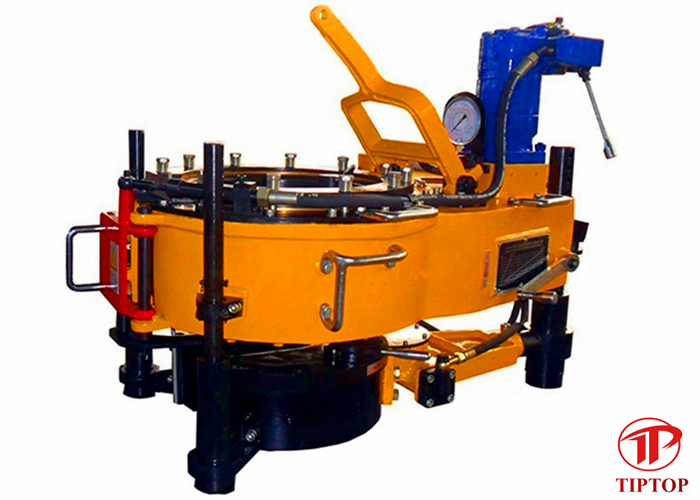
Versatility is the name of the game here as this tong works well whether powered by a workover rig or a portable casing tong power unit. Options include manual backup or cam-type hydraulic backups.
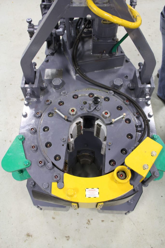
TThe Tri-Grip® Backup is the industry standard for reliable make-up and break-out of tubular connections that are optionally supplied with Eckel tongs. Utilizing two hydraulic cylinders and a three head arrangement ensures a slip-free operation. The backup is suspended at an adjustable level below the power tong employing three hanger legs and allows the backup to remain stationary while the power tong moves vertically to compensate for the connection"s thread travel. The Tri-Grip® uses two pivoting heads and one stationary. The Eckel Tri-Grip® Backup has exceptional gripping capabilities with Rig Dies when running drill pipe or optional Eckel Wrap-Around True-Grit® dies or Pyramid Fine Tooth dies for making up other types of tubular.
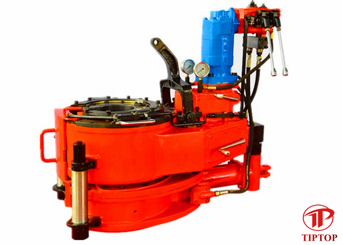
The big, capable Model 36 UHT easily produces 100,000 ft-lb of torque for makeup or break-out operations involving casing in sizes 16 inches through 36 inches. This casing tong weighs approximately 13,000 pounds and is 81 inches wide and 135 inches in length. A two-speed motor delivers 16 RPM in high, 3½ RPM in low range, both at 70 GPM.

Tongs are used for connecting and disconnecting threaded members. Generally, they are used in pairs, one tong (known as a "back-up tong") holding one length of pipe fast and the other tong (referred to herein as a "power tong") rotating a second length of pipe with respect to the first.
Typical power tongs have a rotary with pipe gripping jaws that is rotatably mounted in a housing and is driven in rotation by a gear train powered by an hydraulic motor. The hydraulic motor is usually capable of tightening joints to the required torque, but problems can arise when trying to separate pipes, for example, the pipes of a drill string that has been withdrawn from a bore.
According to the present invention, there is provided in one embodiment a power tong for releasing tight joints, the tong having a housing and a rotary rotatably mounted therein, the rotary having a rotational axis, apparatus for inhibiting relative rotation between the rotary and the housing and apparatus for pivoting the housing with respect to the rotational axis of the rotary. Conveniently, in one embodiment, the apparatus for inhibiting relative rotation between the rotary and the housing comprises a bolt. If desired, at least two bolts may be provided. The bolt (or bolts) may enter the rotary through an upper and/or lower surface thereof and/or through a radial extremity thereof. Alternatively, the bolt (or bolts) may be arranged to project between adjacent teeth on the circumference of the rotary. The bolts may be moved either manually or automatically from a location remote from the tong.
The apparatus for pivoting the housing may be, in one embodiment, a long bar which can be placed in a slot in the housing. In one preferred embodiment, the apparatus is a pair of cylinders connected to opposite sides of the housing and actuable by pneumatic, or preferably hydraulic, fluid to pivot the housing. The cylinders are preferably double acting cylinders so that the power tong can untighten threads clockwise and anti-clockwise and can also be used for applying very high tightening torques which may be required, for example for testing purposes. For this latter purpose, a load cell may be provided from which the torque applied to the joint can be determined.
In another preferred embodiment, the double acting piston and cylinders have an hydraulic section and a mechanical section, and the hydraulic section has a piston connected to an end fitting and disposed in a cylinder between two ports for permitting hydraulic fluid to flow to and from the cylinder, and the mechanical section has a piston disposed in the cylinder and connected to an opposite end fitting, the mechanical section separated from the hydraulic section by a wall. Preferably, the power tong includes cup springs disposed to either side of the piston in the mechanical section.
Filed on even date herewith are two applications co-assigned with the present invention, one entitled Rotary For a Power Tong and one entitled Power Tong, copies of which are submitted herewith and fully incorporated herein.
Referring to the drawings, a bucking unit which is generally identified by reference numeral 1 has a back-up tong 2, and a power tong 3 disposed above the back-up tong 2.
The power tong 3 is supported on three balls, one of which 4, is shown in FIG. 1. The ball 4 rests on a flange 5 on the side of the back-up tong 2 and is biased downwardly by a spring 6 which acts on the ball 4 through a pin 7. The power tong 3 can move upwardly away from the back-up tong 2 during an unscrewing operation.
The piston 8 of a double acting hydraulic piston and cylinder assembly is pivotally mounted on pin 7. The cylinder 9 is pivotally mounted on a support member 10 projecting upwardly from the back-up tong 2. The cylinder 9 is also supported by an arm 11 which is pivotally mounted to the cylinder 9 at pivot 12 and to support member 10 about pivot 13.
As can be seen from FIG. 2, the opposite side of the power tong 3 is provided with a piston and cylinder assembly which is similar to the arrangement hereinbefore described. In particular, a piston 14 is connected to a pin (not shown) associated with a spring and ball similar to spring 6 and ball 4. The piston 14 enters the cylinder 15 of a double acting piston and cylinder assembly which is pivotally mounted on support member 10 and supported by an arm 16 similar to arm 11.
It will be appreciated that the arrangement disclosed allows the power tong 3 to move in three orthogonal dimensions, e.g. along the x, y and z axis. In normal use, the cylinders 9 and 15 will be open to atmosphere and springs 17 and 18 are preferably provided to bias the power tong 3 towards its normal operating position.
The power tong 3 has a housing 19 which houses a rotary 20 which has an axis of rotation through the point 20a and is rotatably mounted in the housing 19. The rotary 20 is provided with jaws 21 which can be moved radially towards the center of the power tong 3. The rotary 20 is guided by a plurality of rollers which are mounted on axles 22 disposed circumjacent the center of the power tong 3. The rotary 20 is connected by a gear train (not shown) to an hydraulic motor 23.
In use, when it is desired to disconnect a joint, the doors 29 and 30 on the power tong 3 and the back-up tong 2 respectively are opened. The travelling frame 36 is then advanced towards the pipe until the pipe enters the power tong 3 and the back-up tong 2. The doors 29 and 30 are then closed and the pipes gripped by the jaws in the respective tongs 2, 3. The hydraulic motor 23 is then actuated. Normally, this will be sufficient to unscrew the joint. However, situations do arise where the joint will not separate and the hydraulic fluid intended for the hydraulic motor 23 is returned to the reservoir via a safety valve.
When this situation arises, the hydraulic motor 23 is deactivated and actuators 24 and 25 are activated to advance plungers 26 until the bolts 27 are disposed between the teeth 28. At this stage, hydraulic fluid is admitted to the cylinders 9 and 15 to push the piston 14 to the left as shown in FIG. 2 and piston 8 to the right. The force tends to rotate the power tong 3 anti-clockwise. Since the bolts 27 hold the rotary 20 fast with the housing 19, the torque is applied to the rotary 20 and thence to the pipe (not shown) via the jaws 21. The cross-sectional area of the cylinders 9 and 15 is such that a substantial torque can be applied to the housing 19 to loosen even the most stubborn joints.
Once the joint is loosened, the bolts 27 can be withdrawn and the joint unscrewed using the hydraulic motor 23 rotating rotary 20 in the usual way. Cylinders 9 and 15 are also vented to atmosphere to allow the power tong 3 to float in the horizontal plane.
In use, end fitting 111 is pivotally connected to the power tong 3 while the other end fitting 107 is pivotally connected to support member 10. A similar double acting piston and cylinder assembly is used on the opposite side of the power tong 3.
In normal operation, the hydraulic section 100 is kept full of hydraulic fluid. However, the passage of hydraulic fluid through ports 102 and 103 is prevented so that the piston 8" is effectively locked with respect to the cylinder 9". However, the arrangement in the mechanical section 101 allows the power tong 3 to float in the horizontal plane.
When it is desired to use the hydraulic section 100 to turn the power tong 3, hydraulic fluid is admitted to the cylinder 9" through, for example, port 103 and a corresponding volume of hydraulic fluid is exhausted through port 102. Thrust is applied to the power tong 3 via end the fitting 111 and the reaction force urges the cylinder 9" to the right (as viewed in FIG. 3) until the short extension 108 abuts the wall 109 whereafter the thrust is transmitted through piston 106 to end fitting 107.
At the end of a joining/unjoining operation, the pressure at ports 102, 103 is allowed to equalize and further passage of hydraulic fluid through the ports 102, 103 is prevented by closing valves (not shown). The double acting hydraulic piston and cylinder assemblies are then in their normal position as shown in FIG. 3 in which the hydraulic section 100 is effectively locked solid and the mechanical sections 101 of each assembly allows the power tong 3 to float in a generally horizontal plane.

The two main choices in gear type are dredge and tong. These two gears are the preferred methods to harvest oysters in the commercial fishery, and have been designed to gather oysters efficiently from their reef habitat. Both dredges and tongs were used in some of the earliest surveys in Chesapeake Bay [10, 11], with tongs being used in shallow water and dredges in deeper waters. Estimates derived from dredges are not accurate due to problems relating to the efficiency of the device [10]. Since these early efforts, more recent studies [3, 12–15] have noted that dredge efficiency is low, highly variable and generally unreliable, though in some cases a dredge may be calibrated to provide a relative measure of population status [14].
There are two types of patent tongs, hydraulic and mechanical. Hydraulic tongs (Fig 1) are closed using hydraulic power, and are heavier than mechanically-operated tongs (Fig 2). Mechanical tongs are held open by a spring-loaded device, which is triggered and releases when the tong hits the bottom. The tong then closes as it is retrieved. When compared to divers, hydraulic patent tongs are assumed to be similar in efficiency to SCUBA divers, which are thought to be 100% efficient [3], but this has not been tested. Divers use digging implements and collect all oysters, live and dead, as well as all shell material down to 10 cm depth from a sample area. Similarly, a hydraulic patent tong collects samples down to 10 cm in depth. Hydraulic patent tongs require a larger vessel with specialized equipment. Instead, monitoring programs often use either the more commonly available dredges or mechanically-operated patent tongs whose efficiency has never been quantified. During a survey, only a single grab of the tong per sample site is taken, so it is important to determine the efficiency rate of this grab vs the total number of oysters present within the grab area, as we do not expect the tong to capture all oysters within a grab area on the first grab. This is the efficiency of the gear; when a sub-sample of this first grab is taken and processed, we consider this “survey efficiency.”
We used mechanically-operated patent tongs to survey an oyster population on a series of restored reefs in the Great Wicomico River (GWR), Chesapeake Bay, USA (Fig 3). These reefs were built in 2004 at varying heights on the bottom and separated into two categories, high relief (≥ 25 cm) and low relief (8–12 cm), and were the world’s largest oyster reef restoration project at the time. They were built out of shells dredged from formerly-productive oyster reefs now denuded of surface shell and covered by sediment. All reefs were built as sanctuaries and relied on natural recruitment to establish an oyster population on the reefs, which occurred (Schulte et al. 2009). Due to the world-wide [16], as well as Chesapeake Bay wide [17, 18] depletion of oysters and destruction of their habitat, oyster restoration efforts are expanding to restore this ecosystem engineer, which provides a wealth of ecological services [19, 20]. Due to significant and ongoing financial commitments in the Chesapeake Bay region towards oyster restoration, a goal implementation team (GIT) was formed in the Bay region, consisting of a mix of state and federal fishery managers, scientists, and those agencies (NOAA and the US Army Corps of Engineers) involved in construction and monitoring of restored oyster reefs. As it had been noted in the Chesapeake Bay scientific community that there is a lack of good monitoring data regarding oyster restoration efforts [21], we were keenly interested in sampling the GWR restoration project accurately and precisely such that results could be compared and contrasted with other restoration efforts as well as to evaluate the success of the reefs. We sampled in the winters of 2007–2008 and 2008–2009 using a device considered to produce very accurate results, a mechanically-operated patent tong with a measured area per grab of 1.03 m2. Tong size can vary, small tongs ranging from 0.1–0.25 m2 being used on smaller boats, which can access shallower reefs than those in the present study. The mechanically-operated patent tong relies on the weight of the device to penetrate the oyster reef and mechanical action to retrieve the sample. This is similar to the action of bottom samplers such as a PONAR grab, and its gear efficiency may be different from either SCUBA divers or the hydraulic patent tong.
While conducting the survey in winter 2007–2008, our patent tong samples were typically full, indicative of obtaining a complete sample. Additionally, there was a thin layer of whitish grey shells at the bottom of the sample, which were the original dredged shells used to construct the reef base of the sanctuary reefs, and were easily distinguishable from live oysters and newly-formed shell after reef construction. The dredged shells had been buried in anoxic sediments for several hundred years prior to their dredging and are distinct in physical appearance, as well as structurally, from new oyster shells [22], which are typically brown in color, longer and thinner.
When sampling reefs in the following year (winter 2008–2009), the patent tong did not appear to obtain a full sample consistently. Many samples, particularly those from high-relief reefs, were only partially full and the original dredged shell was absent from the bottom of the sample, suggesting that some of the live oysters were not collected. ROV video examination of sampled sites indicated that live oysters were being left behind within the sample site footprints. The reefs, especially the high-relief ones, appeared to have accreted substantial reef material, which could preclude the collection of complete samples with the patent tong within a single grab. Such was the case in the late 1800s, when Winslow (1882) sampled oyster reefs in Tangier Sound and Pocomoke Sound in the middle reaches of Chesapeake Bay. Winslow (1882) stated that obtaining accurate samples was much more difficult on high-density, cohesive, unfished beds compared to oyster beds that had been subject to dredging and tonging, due to the cohesiveness and much higher volume of oysters. Unfortunately, none of the earlier studies of oyster survey gear efficiency quantified the effect of reef characteristics on sampling efficiency [3, 10, 12–14]. Consequently, we aimed to assess the efficiency of mechanically-operated patent tongs in sampling subtidal oyster reefs constructed of shells, and determine if reef characteristics affected sampling efficiency.
We hypothesized that (1) hand-operated patent tong gear will be less than 100% efficient in sampling any oyster reef, (2) the patent tong will be more efficient in sampling low-relief reefs compared to high-relief reefs due to the cohesiveness of high-relief reefs, (3) the patent tong will sample adults more efficiently than young-of-the-year (YOY) oysters (= spat) due to the small size of the spat, and (4) processing of a sample will improve the sampling efficiency, due to subsampling selection, leading to a significantly greater survey efficiency than gear efficiency. Subsampling selection consisted of selecting the middle half of a grab, where a metal bar provides for a deeper grab for the middle half, while the two ends, which do not have as much weight to grab with, do not grab as deeply. We believe this will result in a higher efficiency rate for the middle half of the tong compared to either end.
The present invention generally relates to a wrenching tong and other power tongs. Particularly, the present invention relates to a wrenching tong for use in making or breaking tubular connections. More particularly still, the present invention relates to a tong which has been adapted to reduce the likelihood that it will damage pipe connections. More particularly still, the present invention relates to a torque measuring flange for use with a tong.
It is common practice to use a power tong to torque the connection up to a predetermined torque in order to make this connection. The power tong is located on the platform, either on rails, or hung from a derrick on a chain. In order to make up or break out a threaded connection, a two tong arrangement is necessary. An active (or wrenching) tong supplies torque to the section of pipe above the threaded connection, while a passive (or back up) tong supplies a reaction torque below the threaded connection. The back up tong clamps the pipe below the threaded connection, and prevents it from rotating. This clamping can be performed mechanically, hydraulically or pneumatically. The wrenching tong clamps the upper part of the connection and is driven so that it supplies torque for a limited angle.
Normally, in order to supply high torque, the wrenching tong is driven hydraulically. One or two hydraulic cylinders drive the tong through a small angle, typically in the region of 25°, depending on the tong design. Due to the geometric configuration normally used, the torque output of the tong changes as a sine function of the angle driven, which results in a reduction of torque output across the drive angle of up to 15%.
In order to make up or break out a connection of modem drill pipe or casing, high torque must be supplied over a large angle. This angle is sometimes six times higher than a conventional wrenching tong can supply. In order to overcome this, the wrenching tong must grip and wrench the tubular several times to tighten or break the threaded connection fully. This has a number of disadvantages. The action of gripping and releasing the pipe repeatedly can damage the pipe surface. Due to the high costs associated with the construction of oil and gas wells, time is critical, and the repeated clamping and unclamping of the wrenching tong greatly increases the time taken to attach each new section or stand of tubulars. It also has the effect that the torque provided is discontinuous, increasing the difficulty of accurately controlling the torque with respect to the angle turned.
According to a first aspect of the present invention there is provided apparatus for applying torque to a first tubular relative to a second tubular, the apparatus comprising a first tong for gripping the first tubular and a second tong for gripping the second tubular, wherein the first tong is provided with teeth around a peripheral surface thereof, the second tong is provided with at least one pinion, and the pinion meshes with the teeth in such a way that the first tong and the second tong can be rotated relative to one another when the pinion is rotated.
Preferably the first tong is a back-up tong and the second tong is a wrenching tong. Both tongs are preferably substantially cylindrical, and an axial passage is preferably provided therethrough for receiving tubular-s. A passage is preferably provided from a peripheral edge to the axial passage of each tong to allow the introduction of tubulars into the axial passage. The pinion is preferably located at or near the periphery of the second tong. A motor may be provided on the second tong and coupled to the or each pinion.
The second tong is preferably provided with two pinions, although in another embodiment it may be provided with only one. The pinions are preferably located at or near the periphery of the second tong spaced by substantially 180° about the longitudinal axis of the tong. In another embodiment they may be spaced by substantially 120° about the longitudinal axis of the tong.
Preferably, the first tong comprises a plurality of hydraulically driven clamping jaws for gripping the first tubular and the second tong comprises a plurality of hydraulically driven clamping jaws for gripping the second tubular. Each jaw may be equipped with two or more dies, and is preferably attached to hydraulic driving means via a spherical bearing, although the jaw may be an integral part of the hydraulic driving means.
Bearings supported on resilient means are preferably provided between the first tong and the second tong to facilitate relative axial movement of the first and second tongs.
According to a third aspect of the present invention there is provided a method of applying torque to a first tubular relative to a second tubular, the method comprising: clamping the first tubular in a first tong; clamping the second tubular in a second tong; and rotating a pinion connected to the second tong and which meshes with teeth provided around a peripheral surface of the first tong so as to rotate the first tong relative to the second tong.
lowering a tong arrangement having a rotary part and a stationary part, relative to the basket to engage respective locking members of the tong arrangement and the basket, thereby fixing the basket and the tool relative to the stationary part of the tong arrangement; and
This method may be used to couple a tool such as a drill bit, to a length of drill pipe. The coupling portion of the length of drill pipe may be brought into proximity with a corresponding coupling portion of the tool either before or after the lowering of the tong arrangement.
The length of drill string may be gripped by the rotary part of the tong arrangement either before or after the lowering of the tong arrangement. The length of drill string may be located proximate to the basket containing the tool either before or after the string is gripped by the rotary part of the tong arrangement.
a tong arrangement having a rotary portion and a stationary portion, the rotary portion being arranged in use to grip and rotate the length of tubular; and
first locking means provided on the basket and second locking means provided on the stationary portion of the tong arrangement, the first and second locking means being engageable with one another to fix the basket relative to the stationary portion of the tong arrangement.
Preferably the first and second locking means are engageable and disengageble by means of linear movement of the tong arrangement relative to the basket.
Preferably, the basket is arranged to prevent rotation of the tool in the basket, wherein in use the rotary portion of the tong arrangement may be used to rotate the length of drill pipe to secure a screw connection between the length of drill pipe and the tool.
Preferably, one of the first and second locking means comprises one or more slots, and the other of the first and second locking means comprises one or more projecting members, the slots and the members being engageable and disengageable by relative linear movement of the tong arrangement and the basket.
According to a sixth aspect of the present invention there is provided a tong for use in clamping a length of tubular during the making up or breaking out of a connection, the tong comprising:a body portion having a central opening therein for receiving a length of tubular; and
a plurality of elongate mounting members disposed between each of the clamping mechanisms and the body of the tong, each mounting member having a flat face for abutting a side of a clamping mechanism and a rounded side for locating in a complimentary shaped recess in the tong body,
The present invention provides a positioning apparatus for determining the position of a tubular with respect to the tong. The positioning apparatus includes a plunger having an end contactable with the tubular disposed on a base. The plunger may be coupled to a visual indicator to indicate the axial travel of the plunger relative to the base.
In another aspect, the present invention provides a torque measuring flange for determining the torque applied by a motor to the tong. The flange includes a top plate and a bottom plate. The flange further includes one or more wedges disposed about the periphery of the flange. Preferably, two wedges are attached to the top plate and two wedges are attached to the bottom plate. One or more cylinders may be disposed between two wedges, whereby compressing the two wedges causes a piston in the cylinder to compress.
FIG. 6 is a view of the wrenching tong and back-up tong of FIG. 1 supported by a C-frame and fixed in a frame for handling equipment on tracks at a rig floor;
FIGS. 1 and 2 show an arrangement of a composite wrenching tong and back-up tong. A wrenching tong 1 is generally in the form of a disc with an opening 2 through the center thereof for receiving a stand of drill pipe (not shown), and a recess 3 cut from the edge to the opening 2 at the center. The wrenching tong 1 is provided with two pinion drives 4 arranged opposite each other at the periphery of the disc, equally spaced either side of the recess 3. Each pinion drive comprises a drive motor 5, drive shaft 6, and pinion 7 attached to the drive shaft 6.
A back-up tong 11 is located beneath the wrenching tong 1. The back-up tong is generally in the form of a disc with similar dimensions to the wrenching tong 1. The back-up tong is also provided with an opening 12 through the center and a recess 13 from the edge to the opening at the center. The opening 12 and recess 13 correspond to the opening 2 and recess 3 of the wrenching tong when the back-up tong 11 and the wrenching tong 1 are correctly aligned.
A plurality of guide rollers 10 or other guide elements are spaced around the edge of the wrenching tong 1 in order to maintain the alignment of the wrenching tong 1 with the back-up tong 11.
A gear 14 is provided around the periphery of the back-up tong 11, broken by the recess 13. The gear 14 meshes with the pinions 7 attached to the motors 5 on the wrenching tong, so that when the drive motors 5 drive the drive shafts 6 and gears 7, the wrenching tong 1 rotates relative to the back-up tong 11. The angle of rotation is limited by the recess 13 of the back up tong.
FIG. 3 shows a back-up tong 11 before the wrenching tong is placed on top of it. The back-up tong 11 has a plurality of roller bearings 21, upon which the wrenching tong 1 is designed to be placed. The roller bearings 21 are supported by resilient means such as springs, elastic material or hydraulic/pneumatic cylinders, in order to support the wrenching tong during wrenching. During one wrenching cycle, the stands will move axially relative to one another as the connection is tightened. The wrenching tong must follow the axial movement of the top stand during one wrenching cycle. This axial travel length depends on the pitch of the thread.
Three clamping jaws 8 equipped with dies 9 are located inside each of the wrenching tong 1 and back-up tong 11. These are hydraulically driven for clamping the drill pipe stand in place in the center of the wrenching tong. The hydraulic power supply may be provided by hoses (not shown).
FIG. 4 shows the clamping mechanism of the back-up tong 11. Three hydraulic pistons 16, comprising piston rods 17 and chambers 18, are located inside the casing of the back-up tong 11. Each piston rod 17 has an end 19 which is secured to the outside edge of the back-up tong 11. At the other end of the piston, the jaw 8 containing two dies 9 with teeth (not shown) is fixed to the chamber 18 by a spherical bearing 20. With the arrangement shown, each drill pipe stand is clamped by three jaws and six dies at the joint. The spherical bearings 20 enable the jaws and dies to match the pipe surfaces closely, resulting in a low penetration depth of the teeth of the dies into the pipe surface, and thus prolonging the life of the drill pipe. The wrenching tong has a similar clamping jaw design, as shown in FIG. 5.
FIG. 6 shows the wrenching tong 1 and back-up tong 11 supported by a C-frame 22 for handling at the rig. The C-frame 22 is in turn fixed in a frame 23 for handling the equipment on tracks at the rig floor. A drill pipe spinner 24 is mounted on the C-frame above the tongs for rotating a drill pipe stand at high speed.
In order to make a connection between two stands of drill pipe, the recesses 3 and 13 in the wrenching 1 and back-up 11 tongs are aligned (the tongs may already be in this configuration following the removal of the tongs from a previous section of tubing). Two stands of drill pipe 25,26 are then introduced into the openings 2,12 in the wrenching and back-up tongs 1,11, respectively, through the recesses 3,13, and the lower stand 26 is clamped in position in the back-up tong 11. The upper stand 25 is introduced into the drill pipe spinner 24, and rotated at high speed in order to pre-tighten the threaded connection. The final high torque will be applied by the wrenching tong 1.
The upper stand 25 is now clamped in position in the opening 2 through the wrenching tong 1. The pinion drives 4 are then driven to torque the connection between the stands 25,26 until the connection is fully tightened or until one of the pinion drives 4 is at the edge of the recess 13, at which stage the wrenching tong 1 is at one end of its possible arc of travel relative to the back-up tong 11. The maximum wrenching angle which can be reached in one cycle in the embodiment shown is +/−75°. If necessary, the upper stand 25 can then be released from the wrenching tong 1, the tong returned to its original position, and the torquing process repeated.
An even larger wrenching angle can also be simply achieved with this arrangement, as shown in FIG. 7. The stands of drill pipe 25,26 are introduced to the tongs 1,11 through the recesses 3,13 and pretightened using the drill pipe spinner 24 as described above. However, before the top stand 25 is clamped in place in the opening 2, the wrenching tong drive is reversed, and the wrenching tong 1 is driven to its end position relative to the back-up tong, as shown in FIG. 7. The top stand 25 is now clamped with the tongs in this position, so that with the embodiment shown a wrenching angle of 150° is achievable.
FIG. 8 shows a similar arrangement of a composite wrenching tong and back-up tong to that described above. However, in this case only one pinion drive 4 is used, which increases the possible wrenching angle to 300°.
It is to be understood that other variations are possible while still falling within the scope of the invention. For example, the preferred embodiments show an arrangement whereby the pinion drives are mounted on the wrenching tong and the gear is mounted on the back-up tong. However, the arrangement could be the other way round with the pinion drives mounted to the back-up tong and the large gear mounted on the wrenching tong. Such an arrangement is illustrated in FIG. 10.
FIG. 11 illustrates in partial section a modified back-up tong 40 which may replace the back-up tong 11 of the embodiment of FIGS. 1 to 9. The modified tong 40 has only two jaws 41 associated with respective clamping arrangements 42. Each arrangement 42 is held in place within the main body 43 of the tong 40 by a set of four “pendulum” bolts 44. A clamping arrangement 42 associated with four pendulum bolts 44 is illustrated in more detail in FIG. 12 from which it can be seen that each bolt comprises a cylinder cut in half along its longitudinal axis to provide a flat surface and a rounded surface. The flat surface of each bolt 44 abuts the side of the clamping arrangement 42, whilst the rounded side is located in a rounded recess 45 provided in the side of the main body 43 opposed to the clamping arrangement. It will be appreciated that as the bolts 44 are able to rotate within their respective recesses in the tong body 43, each clamping arrangement 42 may pivot slightly about its center. This allows the jaws 41 to conform to the outer surface of a tubular to be clamped when the tubular is for example not perfectly cylindrical.
FIG. 13 illustrates apparatus which can be used in association with a tong arrangement 49 to connect and disconnect a tool such as a drill bit to and from a length of tubular such as a drill pipe. The apparatus comprises a basket 50 which is arranged in use to be placed on the floor of a drilling rig. The basket 50 has an opening in the top thereof for receiving a tool 51 which is to be connected to a length of tubular 52. The opening has a shape which is complimentary to the shape of the tool 51 such that the tool is held securely in an upright position and rotation of the tool within the basket 50 is prevented.
Two opposed sides of an upper plate of the basket 50 are provided with slots 53. These slots 53 are shaped to receive locking members 54 which project downwardly from the lower surface of the back-up tong 55 of the tong arrangement. The operation to connect a tool will now be described.
As shown in FIG. 13, the tool 51 is first located in the basket 50. The length of tubular 52 is moved to a position over the tool (FIG. 14) and is lowered to bring the box of the tubular into engagement with the externally threaded coupling of the tool 51. At this point, the tong arrangement is brought up to the tubular 52 with the jaws of the rotary and back-up tongs being fully opened, and the tong is placed around the tubular 52. The tong arrangement is then lowered within its frame, to a position in which the locking members 54 are received by the respective receiving slots 53 of the basket 50. In this position, the basket is locked to the back-up tong. The jaws of the rotary tong are then clamped against the tubular 52 and the rotary tong rotated, relative to the back-up tong, to tighten the threaded joint (FIG. 15). The jaws of the rotary tong are then released, and the tong arrangement withdrawn from around the tubular. The tubular and the connected tool can then be lifted clear of the basket 50.
FIG. 16 illustrates a positioning apparatus 100 which may be used in association with the tong 1 of the present invention. Typically, the positioning apparatus 100 is mounted onto a lower portion of the tong 1 as shown in FIGS. 18 and 19. The tong 1, in turn, is disposed on a movable frame 23. In one aspect, the positioning apparatus 100 may be used to position the drill pipe 105 in the center of the tong 1. Placing the drill pipe 105 in the center position reduces the possibility that the jaws 8 of the tong 1 will damage the drill pipe 105 when the tong 1 is actuated.
The positioning apparatus 100 includes a plunger 110 slidably disposed on a base 120 as illustrated in FIG. 16. The base 120 may include one or more guides (not shown) defining a track for the plunger 110 to traverse. The plunger 110 is positioned such that it may contact the drill pipe 105 as it enters an opening 12 in the tong 1. A contact member 115 is disposed at a contact end of the plunger 110. A contact support 118 may be used to alleviate the contact force endured by the contact member 115.
The second indicator 172 may be set at a predetermined position on the second elongated slot 162. The predetermined position correlates to the desired position of the drill pipe 105 relative to the tong 1. Generally, the tong 1 will grip the pipe joint 108 instead of the drill pipe 105 during the connection process. Therefore, the diameter of the pipe joint 108 will generally be used to determine the proper location of the drill pipe 105. Because the second indicator 172 is movable, the positioning apparatus 100 is useable with the tong 1 to position drill pipes 105 of various size.
In operation, the positioning apparatus 100 is mounted onto the tong 1 with the plunger 110 protruding towards the opening 12 in the tong 1 as illustrated in FIGS. 18 and 19. As shown, the plunger 110 is in the initial position and the springs 130 are unactuated.
As the frame 23 moves the tong 1 towards the drill pipe 105, the plunger 110 contacts the drill pipe 105 before the drill pipe 105 reaches the center of the jaws 8. Thereafter, the plunger 110 is pushed away from the tong 1 as the tong 1 continues to move closer to the drill pipe 105 as illustrated in FIGS. 17 and 20. Specifically, the plunger 110 slides along the base 120 as the tong 1 moves closer, thereby extending the springs 130. At the same time, the end 180A of the cable 180 attached to the plunger 110 is pushed into the sleeve 190, thereby causing the end 180B of the cable 180 attached to the first indicator 171 to extend further from the sleeve 190. In this manner, the first indicator 171 is moved along the first elongated slot 161.
The drill pipe 105 is properly positioned when the first indicator 171 reaches the level of the second indicator 172 as seen in FIGS. 17 and 20. Thereafter, an operator observing the visual indicator 140 may stop the tong 1 from moving further. After the connection process is completed, the frame 23 is moved away from the drill pipe 105. The biasing members 130 bring the plunger 110 back to the initial position, thereby causing the first indicator 171 to move away from the second indicator 172.
According to another aspect, the movement of the tong 1 may be automated. In one embodiment, the visual locator 140 may further include a first sensor (not shown) to indicate that the first indicator 171 is proximate the second indicator 172. The first sensor is triggered when the first indicator 171 is next to the second indicator 172. This, in turn, sends a signal to a programmable controller (not shown) to stop the advancement of the tong 1. In another embodiment, a second sensor (not shown) may be used to indicate that the first indicator 171 has moved past the second indicator 172. If the first indicator 171 moves past the second indicator 172, the second sensor may send a signal to the programmable controller to prevent the tong 1 from actuating and back-up the tong 1 until the proper position is attained.
FIG. 18 illustrates a torque measuring flange 200 which may be used in association with the tong 1 of the present invention. In one aspect, the flange 200 may be used to measure the torque applied to makeup or breakup the drill pipe 105. Drill pipe connections are generally designed to makeup or breakup at a specific torque. If insufficient torque is applied, the connection may not conform to the requisite specifications for use downhole. On the other hand, if too much torque is applied, the connection may be damaged. As discussed above, the torque applied to the tong 1 can be monitored by measuring the pressure of the drive motor 5. Thus, a torque measuring flange 200 is useful in monitoring and controlling the torque applied to the drill pipe connection.
As indicated earlier, the cylinders 250 are capable of indicating the torque applied by the motor 5. In one embodiment, each cylinder 250 may include a pressure transducer (not shown) for determining the torque applied. The pressure transducer may convert the fluid pressure in the fluid chamber into electrical signals that can be sent to a programmable logic controller (not shown) as is known to a person of ordinary skill in the art. The controller may be programmed to operate the tong 1 based on the signals received. Alternatively, a pressure line may be use to connect the cylinder 250 to a pressure operated gauge. The gauge can be calibrated to read the pressure in the cylinder 250. In this manner, any pressure change in the cylinder 250 can be monitored by the gauge.
If a pressure transducer is used, the pressure in the cylinder 250 can be converted to an electric signal that is sent to a programmable controller. In this manner, the torque applied by the motor 5 can be controlled and monitored by the controller. Alternatively, if a pressure gauge is used, the change in pressure may be observed by an operator. The operator can then operate the tong 1 according to the pressure readings.
In another embodiment, a method of applying torque to a first tubular relative to a second tubular comprises clamping the first tubular in a first tong; clamping the second tubular in a second tong; and rotating a pinion connected to the second tong and which meshes with teeth provided around a peripheral surface of the first tong so as to rotate the first tong relative to the second tong.
In another embodiment, a method of applying torque to a first tubular relative to a second tubular comprises clamping the first tubular in a first tong; clamping the second tubular in a second tong; and rotating a pinion connected to the second tong and which meshes with teeth provided around a peripheral surface of the first tong so as to rotate the first tong relative to the second tong.
In another embodiment, a tong for use in clamping a length of tubular during the making up or breaking out of a connection comprises a body portion having a central opening therein for receiving a length of tubular; at least two clamping mechanisms mounted in said body, the clamping mechanisms being radially spaced about said opening; and a plurality of elongate mounting members disposed between each of the clamping mechanisms and the body of the tong, each mounting member having a flat face for abutting a side of a clamping mechanism and a rounded side for locating in a complimentary shaped recess in the tong body, wherein each tong may be displaced to some extent from radial alignment with the central opening of the tong.
In another embodiment, a positioning apparatus for a tubular in a tong comprises a base; a movable member disposed on the base, the movable member having a first end contactable by the tubular to be positioned within the tong; and an indicator to indicate the position of the tubular within the tong. In yet another embodiment, The tong apparatus further comprises one or more biasing members, wherein the one or more biasing members couple the axial member to the base.
In yet another embodiment, a method for preventing damage to a tubular body when such tubular body is gripped and turned by a tong comprises supplying a tong having a tubular position indicator for indicating a position of the tubular body relative to the tong, and the tong having a torque flange mounted thereto for indicating a torque applied to the tubular body when the tubular body is turned by the tong; indicating the position of the tubular body relative to the tong; and indicating the torque applied to the tubular body when the tubular body is turned by the tong.
With its combination of a creamy yellow center, framed by an earthy green, it tells a story of delicious flavor and natural freshness of a heart-healthy ingredient represented by a brand that makes everything better.
For the first time, users can opt for a rowing machine with an exterior that matches the exuberance and empowerment they feel on the inside when they complete a workout. @hydrow has launched, a special-edition Wave Rower in the Pantone Color of the Year 2023.
With its combination of a creamy yellow center, framed by an earthy green, it tells a story of delicious flavor and natural freshness of a heart-healthy ingredient represented by a brand that makes everything better.

Find parts you need to repair or maintain your machines. At Alibaba.com, you can shop for power tong spare parts at affordable rates to tackle new obstacles and challenges. In the ever-changing industry, you can find what you need and speak to the supplier directly. Thanks to Alibaba’s collection of wholesale power tong spare parts you also get to buy these parts at lower prices, which means you can explore new levels every day more comfortably. From bulldozers to dragline excavators, wheel tractor scrapers to shotcrete machines, any part you need for a heavy-duty mining machinery; you can find it at Alibaba.com.
Looking for purpose-built machine parts? Find them at Alibaba.com. From new components to used parts straight from the manufacturers. Plus, if you need custom-made pieces, you can chat with the supplier, give specifications and wait on delivery. From stone crushers to excavator undercarriage parts, buckets, and even drill bits to get you through the rocks, the power tong spare parts from Alibaba offers you the chance to continue operating without a hitch. Whether you are looking to introduce concrete into the rock walls for more consistency and safety during mining, then power tong spare parts that goes at wholesale prices at Alibaba will be an excellent addition to your machinery.
Before buying a component, you’d want the equipment to suit your application and offer value. The list of power tong spare parts at Alibaba.com lets you dig into earth deposits, and the compare tool checks out other similar parts to give you the information you need to make a purchasing decision. You’ll get wholesale power tong spare parts that specializes in mining, with reinforced chassis, and run on more powerful engines. Whether you want to transport minerals or the workers to the mining site, introduce explosives or arms to help you remove materials from your mine pits, Alibaba.com has it all.
Welcome to Free Powerpoint Templates Design, one of the most usefull PowerPoint templates resource website : ALLPPT.COM ! We provide you a fantastic collection of Free Powerpoint Templates Design that you can download for free and regulate for your personal Presentations. Discovering and getting the most related and suitable Powerpoint Templates are as simple as few clicks. You can simply impress your audience and add a unique zing and appeal to your Reports and Presentations with our Templates.
Our Free Powerpoint Templates Design ,Free Powerpoint Diagrams design and Free Powerpoint charts design are appropriate for business and lecture room presentations on education, health, trading, as well as basic-purpose designs together with seasonal Powerpoint Template that you can use to make Presentations. Our PowerPoint Templates design is an on-line useful resource the place you can browse and download free royalty background designs, PowerPoint illustrations, Photo graphics.
Download Free Powerpoint Templates Design now and see the distinction. What you will have is a further engaged target market, and the go with the go with the flow of information is clean and quick.Our site is UPDATED EVERY DAYwith new Powerpoint Templates.
Head motion can systematically bias neuroimaging studiesn = 3,928 youth across the discovery (n = 1,964) and replication (n = 1,964) sets. The final discovery and replication sets did not differ in mean framewise displacement (difference in means = 0.002, t = 0.60, P = 0.55) or total frames included (difference in means = 6.4, t = 0.94, P = 0.35). The participant lists for ARMS samples can be found in the ABCD-BIDS Community Collection (ABCD collection 3165) for community use
Imaging was performed at 21 sites in the United States, harmonized across Siemens Prisma, Philips and GE 3T scanners. Details on image acquisition can be found in ref. 3, 60 slices). Head motion was monitored using framewise integrated real-time MRI monitoring (FIRMM) software at many of the Siemens sites
ABCD RSFC data consists of 4 × 5 min runs. For each participant with full brain coverage, all available RSFC data were concatenated and high motion frames (filtered-FD > 0.08) were censored. The timeseries of BOLD activity for each ROI was correlated to that of every other ROI (333 cortical ROIs from Gordon et al.z-transformed. For network level analyses, correlations were averaged across previously defined canonical functional networks
False negative (Fig. 3a) and false positive (Fig. 3f) rates were derived through resampling (see ‘Resampling procedures’) for all edge-wise brain-wide associations. For each sample size bin (16 total), we randomly sampled with replacement n individuals (1,000 subsamples) and computed the brain–behavioral phenotype correlation and associated P value. A correlation was deemed significant if it passed a threshold (P value range: <0.05 to <10−7 (Bonferroni-corrected) across 77,421 ROI–ROI pairs) in the full sample (cortical thickness n = 3,604, RSFC n = 3,928). At each sample size, if a correlation in the full sample was not significant, we determined the percentage of studies that resulted in a false positive significant correlation across a broad range of P values (0.05 to 10−7). Conversely, if a correlation in the full sample was significant (P < 0.05 to 10−7), we determined the percentage of studies that resulted in a false negative non-significant correlation across a broad range of P values (10−7 to 0.05). Statistical power (Fig. 3d) was calculated as 1 − false negative rate.


 8613371530291