
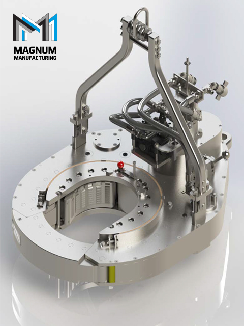
power tong frame top view factory
The present invention relates to power wrenches and, more specifically, to power tongs for making up and breaking out threaded connections between adjoining tubular members.
In particular, the invention relates to a novel arrangement used to join the tong cage plates and the rotary gear for joint rotation to facilitate proper alignment of the tong parts for placing the tong on the pipe or removing the tong from the pipe. The novel arrangement also serves the novel function of preventing so-called "overcamming" situations wherein the pipe gripping mechanism of the tong does not grip the pipe due to various fa-ctors, such as the jaws being undersized or the pipe being oversized.
Oil field tubular members, e.g., drill pipe and casing, are employed in sections which are joined togethèr at their ends by threaaed connections. Power tongs of the type herein described are utilized to make up and break out these threaded connections by securely gripping one tubular member and rotatably driving that member relative to the adjoining me`mber. Tongs reprPsentative of present practice in the industry are described in U.S. Patent Nos. 2,879,680; 3,180,186;
When a power tong is used to grip and rotate a pipe section, a pipe-gripping mechanism as described, for example, in U.S. Patent No. 2,879,680, is utilized to brin-g a pair of jaws into contact with the pipe. The jaws are pivotally " . ` . `
- In pipe gripping operations, the jaws (or dies carried thereon) may fail to securely grip the pipe due to various factors. In such cases it is desirable to refrain further relative movement between the rotary gear and cage plates to prevent dangerous overcamming situations where the rotary gear continues to rotate after the camming action fails. No known tong structure adequately solves this problem.
A second problem in tong operation addressed by the instant invention is that of alignment of the tong parts prior to placing the tong on the pipe or removing the tong from the pipe. In an open mouth tong of the type described herein, three openings must be aligned before the tong may be placed on or removed from a pipe--the tong throat, the rotary gear mouth and the cage plate mouth.
According to prior art practices, this alignment function has been accomplished by the use of a backing lug/backing pin arrangement. Accord-ing to this prior art technique, a "backing lug" is secured to the inside surface of a rotary gear by means of a fastener and protrudes toward the center of the tong. The backing lug cooperates with a backing pin which may be placed into either of two openings in the upper cage plate. In the operation of this well-known prior art assembly in a make up operation, after the casing has been made up to the ,: . - . : , :
esired torque the rotary gear is driven in the reverse direction to disengage the jaws and rotates in that direction until -the backing lug engages the backing pin-" At the point of this engagemen-t the mouths of the rotary gear and cage plates are aligned and with -continued rotation of the rotary gear and cage plates may be rotated to the point where the aligned mouths align wlth the throat of the tong. At this time all three open-ings are aligned and the tong may be removed from the pip~. A
A problem associated with the described prior art technique is that in situations where the rotary gear is rotating at a relatively fast rate of speed (for example, when the tong is in high gear and the throttle valve is completely open) the force exerted at the instant the backing lug contacts the backing pin may result i~ a sheared backing pin or a sheared backing lug, or both. Such situations are,costly in terms of time of replacement and repair since the tong must be partially disassembled to replace a backing lug and due to the further problem that a broken pin may fail downhole and cause problems for rig opera-tion personnel.
The described alignment technique has proved moderately successful in practice, but has caused the noted problems with reliabili~y and tong downtime. : It is therefore an object of an aspect of of the present invention to overcome disadvantages associated with this and other prior art techniques and to provide means for substantially preventing costly and dangerous overcamming situations~
In accordance with a broad aspect of with the present invention there is pro~ided a power tong for making up and breaking out connections between ad~oining tubular members. Specifically, in its broad aspect, the instant invention provides a power tong having a novel arrangement for preventing dangerous "overcamming"l situations when the gripping elements of the tong fail to grip the pipe after the camming action is sub-stantially complete and for facilitating the alignment o~ the tong parts when it is desired to-place the tong on a pipe or " remove the tong from the pipe.
In a particular embodiment, the power tong of the present invention comprises a frame with a pipe receiving throat and mounting cage plates, a rotary gear mounted for rotation within the frame, means for rotatably driving the rotary gear, cam surfaces on the ,inner surface of the rotary gear, pipe-gripping ,means which include gripping elements and cam follower rollers for engaging the cam surfaces and urging the gripping elements into enga~ement with the pipe, a pair of arcuate grooves formed in the upper surface ~f the rotary gear, a pair of apertures formed in the upper cage plate residing above the rotary gear, and a pin me~ber sized to pass through either one of said open-ings and into a respective groove for joining the frame and the rotary gear for joint rotation when the pin engages theends or - boundaries-of the grooves during rotation of the rotary gear.
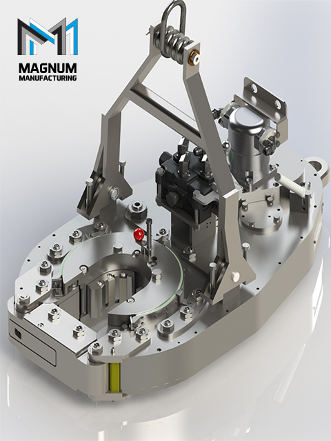
In the accompanying drawings, Figure l is a pictoral view of an open mouth power tong con-structed in accordance with an embodiment of the present invention.
Figure 5 is a view similar to Figure 4 illustrating the rotary gear with the cage plates, jaws, and pin in an operative position as the pin/recess combination of an embodiment of the invention prevents overcam-ming during a make up operation.
Figure 6 is a section view taken substantially along line 6-6 oE Figure 5 and illustrating the pin extending through one of the two openings in the cage plate and into one of the grooves in the rotary gear.
Referring to the drawings and in particular to Figures 1-3, an open-mouth power tong,l0 constructed in accordance with a preferred embodiment of the present invention is shown.
Tong 10 includes a frame 12 comprising upper and lower surfaces connected by sidewalls. A body plate of the upper surface supports an upper cage plate 25 which, in turn, pivotally supports the jaws 44, 46 utilized to grip the pipe sections. A
cage plate 25 and also supports the jaws. The cage plates are joined by sui-table spacers such as spacers 31 shown in Figures 2 and 3. Frame 12 defines a frontal throat 18 for receiving the pipe sections. When a pipe section is centrally located within the frame during operation, throat 18 is closed off by means of pivotally mounted door members 20, 22 in the manner well known in the art.
The pipe-gripping mechanism of the tong will be described - with primary reference to Fïgures 1, 4 and 5. A rotary gear 30 is mounted within frame 12 for rotation relative to the frame. Rotary gear 30 includes gear teeth 32 (Figure 4) on its outer periphery so that it may be driven in the manner well known in the art, for example, by means of a plurality of pinion gears. The pinion gears, in turn, may be suitably driven by a hydraulic drive train or other drive system. The - inner surface of-the rotary gear 30 is substantially circular and includes cam means comprising curved cam surfaces 70, 71, 72, 73 for urging the pipe-gripping elements into contact with the pipe. In the illustrated embodiment the pipe-gripping elements comprise dies 36, 37, 38, 39 mounted on a pair of pivotally mounted jaws 44, 46. The jaws are urged toward the pipe P by means of cam followers comprising jaw rollers 50, 52 which are rotatably mounted on the jaws by pins 56, 58. The jaws 44, 46 are, in turn, pivotally mounted between the cage plates 25 and 40 by means of jaw pivot bolts 66, 68. Rollers 50, 52 are adapted to ride on the cam surfaces 70, 71, 72, 73 on the interior of the rotary gear 30.
- 6 a -~, : : ; . ` :,: ;, . . : , ~2~7~1 According to an embodiment of the present invention, two radial grooves or recesses 100, 102 are mach:Lned into the top surface of the rotary gear (seè Figures 4 and 5). Make-up recess 100 is used in make-up operations and break-out recess 102 is used in break-out operations in the manner described below. An elongate pin 110 having a hand engageable knob 112 is movably secured to the upper cage plate by means of a pin mount 116. Mount 116 enables pin llO to be moved to either a first make-up aperture 120 or a second break-out aperture 122 in the upper cage plate.
moves arcuately inside groove 100 allowing the jaw cam action to function as earlier described. In those ins-tances where a pipe is undersized or the jaw rollers are undersized or worn, or a combination of both conditions exists such that the jaws do not grip the pipe before the rollers reach the extremities of the cam surfaces, an overcamming situation is prevented due to the cal-cul~ted length of the radial groovesO In such an instance, pin 110 simply moves to the remote boundary 140 of groove 100 and, if - the jaws have not gripped the pipe by this time, the cage plates will begin rotating in conjunction with the rotary gear. Xefer-ring to Figure 5, it will be noted that the roller 50 stops its motion at a safety distance "D" ~rom the mouth of the rotary gear.
A second function of the above-described combination is in the alignment of the rotary gear mouth and the cage plate mouth when it is necessary to initially place the tong over the pipe or remove the tong from the pipe. ~s stated above, the tong frame includes a throat 1~. When placing the tong on pipe or removing the tong, there are thrèe openings which must be aligned--throat 18, the rotary gear mouth the cage plate mouth.
The apparatus of an embodiment of "the instant invention provides a reliable and - simple means for accomplishing this function. For example, when a make-up operation is complete and it is desired to remove the tong from the pipe, the direction of rotary gear rotation may be reversed to counterclockwise so that pin 110 retraces its path through groove 100. When pin 110 reaches the near boundary 141 of groove 100, the rotary gear mouth and cage ; - 8 -l~fi~
Rotation is continued until the aligned mouths of the rotary gear and cage plates come into alignment with the throat 1~ of the tong. At this point, the tong may be removed from the pipe.
The foregoing description of operation describes the prevention of v~ercamming and the alignment of the rotary gear and cage plate mouths with the tong throat in make-up operations. The same functions may be achieved in break-out operations wherein pin 110 is inserted through open~
Thus, it can be seen that a relatively simple, safe and reliable means has been provided for preventing dangerous and costly overcamming situations in the operation of power tongs and for performing the rotary gear/cage alignment function previously performed by the backing lug/back-ing pin combination.
According to prior art practices as illustrated in Figures 7 and 8, this alignment function has been accomplished by the use of a backing lug/backing pin arrangement. According to this prlor art technique, a "backing lug" 200 is secured to the inside surface of the rotary gear 230 by means of a fastener 202 and protrudes toward the center of the tong.
The backing lug 200 cooperates with a backing pin 210 which may be placed into either of two openings in the upper cage plate 225 (opening 205 shown in Figure 7). In the operation of this well-known prior art assembly in a make up operation, after the casing has been made up to the desired torque the rotary gear is driven in the reverse direction to disengage the jaws and rotates in that direction until the backing lug 200 engages the back-ing pin 210. At the point of this engagement the mouths of the rotary gear and cage pLates are aligned and with continued rotation of the fi7~) rotary gear and cage plates may be rotated to the point whe~e the aligned mouths align with the throat of the tong. At this point where the aligned mouths align with the throat of the tong. At this time all three openings are aligned and the tong may be removed from the pipe. A reverse operation is utilized for removing the tong after a break out operation.
Field of Invention The present invention relates to power tongs of the type used to make up and break out oilfield tubulars. More particularly, this invention relates to a power tong designed to minimize marking of a tubular by the tong dies, which is particularly important for chrome plated tubulars.
Background of the Invention Hundreds of patents have been granted for power tongs designed to make up and break out oilfield tubulars. Most commercially successful power tongs have an open throat so that the power tong can be moved laterally on or off the tubular. Power tongs with closed throats have utility for certain applications, but generally are not as widely used as rig power tongs for connecting and disconnecting tubulars as they are run into and out of the well. Chrome plated tubulars are being increasingly popular due to the increased protection provided by highly corrosive downhole environments. The advantage of plating the tubular is substantially sacrificed, however, if the tong dies which make up the connection "mark" the OD of the tubular to the extent that the chrome plating is pierced. When the tubular is then placed downhole, corrosive fluids may acton this damaged area, thereby corroding the steel tubular, and may spread as the corrosive fluids get under the chrome layer. In an attempt to minimize marking of chrome plated tubulars, some power tongs have employed aluminum dies. Aluminum substantially reduces markings since the aluminum material is softer than both the chrome and the oilfield tubular. The problem with this practice is that the aluminum dies, which reduce marking by providing relatively smooth biting surface, do not adequately grip the tubular to perform the makeup or breakout operation. Accordingly, aluminum dies in power tongs commonly slide on the tubular surface during the makeup or breakout operation, which then further scrapes and damages the chrome plating on the oilfield tubular.
U.S. Patent 4,084,453 discloses a power tong with a rotary cage plate and a rotary gear with a relatively low cam angle for cooperation with gripping heads. This tong, which performs satisfactory for many applications, does not provide the minimum marking necessary for use on chrome plated oilfield tubulars. The disadvantages of the prior art are overcome by the present invention, and an improved power tong as hereinafter disclosed, which is particularly suitable for taking up and breaking out chrome plated oilfield tubulars.
Summary of Invention In one embodiment, a power tong for rotating a tubular to make up or break out a threaded connection comprises an open throat tong frame, and partial ring rotatably mounted. on the frame about a center of rotation, with the ring defining a plurality of cam surfaces on an interior surface of the ring, with each cam surface having a neutral cam portion, a makeup cam portion and a breakout cam portion. A cage plate is provided rotatable with the ring, and a plurality of dies are supported on the cage plate and adapted to move radially in response to movement of the dies along with the cam surfaces. The drive mechanism is provided for rotating the ring, the cage plate assembly and the dies to rotate the tubular. An arcuate brake band is provided for frictional engagement with the cage plate assembly, and a brake band fluid powered cylinder selectively increases frictional forces between the brake band and the cage plate assembly. In another embodiment, the power tong includes a pair of dies each supported on the cage plate assembly and adapted to move radially in response to movement of the dies along the cam surfaces. A neutral cam portion of the cam surface is spaced radially outward from an imaginary circle intersecting radially inward edges of the open throat of the ring gear by a spacing of at least 25% of the imaginary circle diameter. Each of the makeup cam portion and the breakout cam portion of the partial ring preferably have a cam angle less than about 3/4°. In still another embodiment, the power tong includes an arcuate brake band for frictional engagement with a cage plate assembly, with a brake band having an axially
extending height of at least 35% of the width of the open throat of the cage plate. An arcuate plate extending upward from the cage plate is provided for engagement with the brake band. A feature of the invention is that the ring and cage plate assembly each have an open throat for moving the tubular laterally into and out of the central opening in the tong frame. As another feature of the invention, the dies are formed from aluminum and have a knurled surface, preferably with the depth of less than 0.015 inches. Each of the dies engages a tubular over a circumferential length of at least 170°. As another feature of the invention that the neutral cam portion of the cam surface is spaced radially outward from an imaginary circle intersecting radially inward edges of the throat of the ring plate by a spacing of at least 25% of the imaginary circle diameter. Each of the cam makeup and breakout surfaces of the partial ring have a cam angle less than about 3/4°. Another feature of the invention is that the brake band has an axially extending height of at least 35% of the width of the open throat of the cage plate assembly. An arcuate plate extends upward from the cage plate for engagement with the brake band. These and further features and advantages of the present invention will become apparent from the following detailed description, wherein reference is made to the figures in the accompanying drawings.
Brief Description of the Drawings Figure 1 is a top view of a power tong according to the present invention. Figure 2 is a side view of the power tong shown in Figure 1. Figure 3 is a top view of the partial ring gear for the power tong. Figure 4 is an exploded view of a portion of the power tong.
Detailed Description of Preferred Embodiments Figure 1 discloses a power tong 10 having a tong frame 12 including upper and lower tong plates 14, 16, shown in Figure 2. The power tong 10 has a central opening 11 for receiving the tubular to be rotated. A geared rihg 20 as shown in Figure 3 is supported between the tong plates on circumferentially arranged roller bearings 18, as shown in Figure 1. Ring 20 includes a pair of interior cam surfaces 22, which each comprise a neutral cam portion 24, a makeup cam portion 26 and a breakout cam portion 28. A cage plate assembly 30 is rotatably mounted with the ring 20, and rotates on cage plate bearings 31. The cage plate assembly includes an upper cage plate 42 and a lower cage plate 44 as shown in Figure 4. A pair of dies 32 supported on the cage plate assembly are adapted to move radially inward and outward in response to engagement with the cam surfaces to engage and disengage the tubular. A conventional drive mechanism 34 including hydraulic motors and gearing engage the outer teeth 21 of the ring 20 to rotate the ring during the makeup or breakout operation. Figures 1 and 2 also depict a conventional door 60 which is closed to cover the open throat of the power tong when the ring member and cage plate are rotated. The dies as shown in Figure 1 preferably are formed from aluminum and include a knurled surface for engagement with the tubular. Knurling on a dies preferentially has a knurled depth (depth of knurling to face surface of dies) of about 0.010 inches, and preferentially less than about 0.015 inches. The dies preferentially wrap substantially entirely around the oilfield tubular, and each of the dies as shown in Figure 1 have a circumferential length of at least 100°, and preferably at least 170°, for engagement with the tubular. Referring to Figure 4, the aluminum dies 32 are each mounted on a respective die head 36. A pin 38 secures a cam roller 40 to the die head, and the roller 40 is the member that rides up the cam surface during the makeup and breakout operations. Referring again to Figure 3, the location where a die roller 40 resides on the cam surface when the dies first engage the pipe during a makeup or breakout operation is depicted with the die rollers 40. Two die rollers thus engage the makeup surface during the makeup operation, and the same two dies engage the breakout surface during the
breakout operation. Preferentially, this cam surface has a cam angle, i.e., the angle between the center 41 of the ring 20 and the center of the cam surface at the location of the roller when the die first engages the tubular, which is less than about 3/4°, and preferably about 1/2°. Further detail with respect to the calculations of the cam angle is provided in U.S. Patent 4,084,453, hereby incorporated by reference. This very small cam angle provides substantially increased gripping of the aluminum die with the tubular. Due to the circumferential length of the dies, the cam surface is provided with a radially deep or radially outward neutral cam portion, as shown in Figure 3. This neutral cam is at least approximately 25% radially outward, and typically from 25% to about 30% radially outward, of an imaginary circle 48 which includes the inner points of the throat of the ring gear 20, as shown in Figure 3. In order to achieve a high biting force of the dies with the tubular before rotation of the cage plate assembly, the tong 10 is provided with a robust brake band 50. As shown in Figure 2, the brake band extends axially upward from the top plate 14 of the tong a substantial distance, typically in excess of four inches. More particularly, the axial height of the brake band 50 is at least 35% of a width of the open throat of the cage plate, and in many embodiments will be at least 40% of the width of the throat of the cage plate. As the size and the torque level of the power tong increase, both the powered brake band and the engaging plate secured to the cage plate assembly may be provided both above and below the cage plate assembly, rather than merely above the cage plate assembly. An arcuate plate 52 is secured to the cage plate assembly 30 and is positioned radially within the brake band, which similarly extends upward to provide a frictional surface for engagement with the brake band. Increased force between the cage piate assembly and the brake band is provided by the fluid powered cylinder 54 which acts to pull the brake band halves together during the initial grip of the heads with the tubular. The brake band cylinder is preferably hydraulically powered, but alternately could be pneumatically powered or powered by a small motor and gear mechanism. According to one embodiment, the tong operator notices initial rotation of the cage plate assembly, and in response thereto releases the fluid pressure to a cylinder
54, thereby effectively releasing the brake band from high frictional engagement with the cage plate assembly. In another embodiment, a sensor may be used to sense initial rotation of the cage plate assembly, so that fluid pressure to the cylinder may be automatically released in response to the sensor. Those skilled in the art should appreciate that a substantially tall brake band 50 is preferably provided according to the present invention, so that the size of the fluid powered cylinder which pulls tension on the brake band to grip the cage plate assembly may be relatively compact and inexpensive. The size of the brake band could be decreased if the power supplied by the cylinder 54 were increased. The pins 56 at the forward end of the brake band extend upward from the cage plate 14, and are each supported by the brake band support 58, which is a plate like member extending from the pin toward the edge of the tong plate, and is secured to the tong frame to support the pin 56. Each of the tong frame 12, the partial ring gear 20 and the cage plate assembly 30 as shown in Figure 1 have an open throat so that the tong can be moved laterally on and off the tubular during a makeup operation. The concepts of the present invention are also applicable, however, to a closed throat tong in which the tong plate, gear ring and cage plate assembly are continuous with no open throat portion. The foregoing disclosure and description of the invention is illustrative and explanatory of preferred embodiments. It would be appreciated by those skilled in the art that various changes in the size, shape of material, as well as in the details of the illustrated construction or combination of features discussed herein may be made without departing from the spirit of the invention, which is defined by the following claims.
The present invention relates generally to making up and breaking out wellbore tubulars and, more particularly, to apparatus and methods for a simplified self-contained power tong for use in a rig floor environment.
Power tong systems maybe used to spin, makeup, or connect and breakout or disconnect wellbore tubulars that may have a wide range of diameters. Comparison studies between use of traditional separate tongs and spinners as compared with a self-contained power tong system makeup and breakout tool working under similar conditions have shown cost savings that range from one-quarter of a million to more than a million dollars per well, depending on the well conditions.
Separate, manually operated tongs, spinners, and/or chains are significantly slower and less accurate and consistent in making up and breaking out wellbore tubulars than a single tool or unit that does all such functions. Besides increased speeds of making up and breaking out tubular connections, other time saving advantages of a self-contained power tong unit also include factors such as eliminating the need to redress tongs when changing from drill pipe to drill collars and the integration of spinning with makeup and breakout functions. Due to the high daily cost of drilling rigs, comparison studies show that the time/cost savings can be substantial.
The self-contained power tong system also operates more reliably than separate tongs and spinners and may provide a central torque regulator that connects to and controls all components to assure consistent makeup. This feature prevents thread damage caused by over-tightening and automatically prevents errors that could result in under-torqued connections. Obviously, a single error, when making up hundreds of threaded connections in a drill string, can result in huge costs of time and material, and even loss of a well.
The self-contained power tong system also eliminates accident conditions commonly associated with separately moveable independent tongs which apply high torque and which are located by personnel on the floor. As well, independent tongs have attendant separate cables used to pull on each separate tong, and may also use snatch blocks. Thus, the personnel must work between high tension cables that pull on the tongs and accidents can easily occur under such conditions, e.g., if a tong loses its grip and moves rapidly across the rig floor accelerated by the high tension on the cable. Of course, accidents can slow work progress and significantly increase the costs of drilling.
Safety is also improved because the invention provides a single tool to perform all such functions, rather than separate elements, permits the use of central safety features such as, for instance, a lockout to prevent spinner operation if the tongs are not engaged, a safe location for the operator to stand and work, a design whereby the operator"s hands and feet are safely away from moving parts, elimination of spinning chains, and a lockout to prevent operation of the lift cylinder when any tong is engaged.
Because of the great utility of prior art self-contained power tong units to makeup and breakout pipes, and the increasingly expanding market for such devices, it has been found highly desirable to make further improvements. It would be highly desirable to simplify the operation of such devices thereby reducing the number of components necessary for operation of the power tong unit. Consequently, there remains a need for an improved self-contained makeup and breakout unit that reduces the complexity and therefore the costs such as manufacturing costs and maintenance thereof. Those skilled in the art have long sought and will appreciate the present invention which addresses these and other problems.
The present invention was designed to provide more efficient operation to thereby reduce drilling costs, to improve reliability of making and breaking pipe joints, to permit increased automation to reduce required manpower, to improve safety, and to free other rig equipment for other uses.
Accordingly, the invention comprises, in one embodiment thereof, a power tong system operable for making and breaking joints between wellbore tubulars. The power tong system may comprise one or more elements such as, for instance, a frame, a spinner secured to the frame that is operable for spinning the wellbore tubulars for the making and breaking of the joints, and/or a first member pivotally connected with respect to the frame such that the first member is rotatable with respect to the frame. The first member preferably defines a bore and/or a slot therein for receiving the wellbore tubulars. Other elements may, for instance, comprise a first plurality of gripping members mounted to the first member which are movable inwardly and outwardly for gripping and releasing the wellbore tubulars, and/or a piston/cylinder assembly comprising a piston slidable within a cylinder. The piston/cylinder assembly may be pivotally mounted with respect to the frame and with respect to the first member such that the first member is rotatable with respect to the frame in response to movement of the piston with respect to the cylinder. Additional elements may comprise a second member mounted to the frame also defining a slot therein for receiving the wellbore tubulars and a second plurality of gripping members mounted to the second member. The second plurality of gripping members may also be movable inwardly and outwardly for gripping and releasing the wellbore tubulars.
The power tong system may further comprise a control arm mounted to the first member, the control arm may be moveable between a first position and a second position, the first member may be rotatable for tightening the wellbore joints in the first position, the first member may be rotatable for loosening the wellbore joints in the second position. Other elements may comprise a fastener for selectively securing the control arm in the first position or the second position. In one embodiment, the fastener further comprises a pin, latch, or other fastening means.
The power tong system may further comprise a pivotal connection between the control arm and the first member and/or a pivotal connection between the control arm and the piston/cylinder assembly.
A method for a power tong system for making and breaking joints between wellbore tubulars are provided that may comprise one or more steps such as, for instance, mounting a plurality of gripping members to a rotatable member, providing that the gripping members are moveable inwardly toward the tubulars for gripping the wellbore tubulars and moveable outwardly away from the tubulars for releasing the wellbore tubulars, pivotally mounting a control to the rotatable member, connecting a piston/cylinder assembly which may comprise a piston and a cylinder, to the control arm such that the rotatable member rotates in response to movement of the piston with respect to the cylinder, providing that the control arm is moveable between a first position and a second position, providing that when the control arm is in the first position, then the member is operable for applying torque to the wellbore tubulars for making the joints, and/or providing that when the control arm is in the second position, then the member is operable for applying torque to the wellbore tubulars for breaking the joints.
The method may further comprise providing a frame, and pivotally mounting the rotatable member to the frame. The method may further comprise mounting a tubing inspection tool to the frame. The method may further comprise utilizing the tubing inspection tool for locating the joints with respect to the rotatable member.
In yet another embodiment, the power tong system may comprise, a frame, a first member pivotally connected with respect to the frame such that the first member is rotatable with respect to the frame, a first gripping assembly mounted to the first member for gripping and releasing the wellbore tubulars, a second member mounted to the frame, a second gripping assembly mounted to the second member for gripping and releasing the wellbore tubulars, lift members attached to the frame for moving the first member and the second member upwardly and downwardly to align the first member and the second member with respect to the joints, a joint connection detector operable for detecting joint connector components for producing a joint signal to indicate the joint connection components wherein the joint connection detector may be in a clearance position with respect to the joint connection components, and an automatic control for receiving the joint connector. The automatic control may be operable for operating the lift members to automatically align the first gripping assembly and the second gripping assembly with respect to the joints.
The system may further comprise automatic slips and a sender for the automatic slips that is used to send status information which may be received by the control. A plurality of sensors may be provided which are operable for measuring pressure, movement, and the like, and may be used, for instance, for determining torque versus turn during the making up of the joints. Other elements may comprise a piston/cylinder assembly which includes a piston slidable within a cylinder wherein the piston/cylinder assembly may be pivotally mounted with respect to the frame and/or a control arm mounted to first member. The piston/cylinder assembly may be pivotally connected to the control arm such that the first member is rotatable with respect to the frame in response to movement of the piston with respect to the cylinder.
FIG. 1 is an elevational view, partially in phantom lines, showing a tong in a first position and selectively rotatable in a first direction in accord with one embodiment of the invention;
FIG. 2 is an elevational view, partially in phantom lines, showing the tong of FIG. 1 in a second position after rotation in the first direction in accord with one embodiment of the invention;
FIG. 3 is an elevational view, partially in phantom lines, showing the tong of FIG. 1 in a first position and selectively rotatable in a second direction in accord with one embodiment of the invention;
FIG. 4 is an elevational view, partially in phantom lines, showing the tong of FIG. 3 in a second position after rotation is the second direction in accord with one embodiment of the invention;
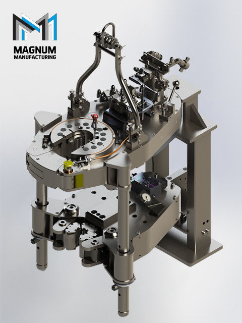
Referring now to the drawings and more particularly to FIG. 1, there is shown a preferred embodiment of rotatable tong 12 for applying torque to tubular connections. In FIG. 5 there is shown one possible embodiment of self-contained power tong system 10 in accord with the present invention utilizing one or more rotatable tongs 12 for applying torque to tubular connections.
Rotatable tong 12 may be utilized as an upper tong or a lower tong and may also be used for both an upper tong and a lower tong which operate in conjunction with each other by rotating in opposite directions. In the embodiment shown in FIG. 5, upper rotatable tong 12 operates in conjunction with a lower fixed position lower tong 14. Thus, upper tong 12 rotates and applies torque to upper pipe 16 while lower tong 14 acts as a back-up tong for holding lower pipe 18 in a fixed position. While in a preferred embodiment, lower tong 14 does not rotate, lower tong 14 could also be designed to rotate in an opposite direction with respect to upper tong 12, thereby doubling the degree of potential rotation available per operation for application of torque to joint 20. Upper tong 12 and lower tong 14 effectively provide sturdy upper and lower members which also support gripping members, as discussed below, in a suitable manner for applying high forces to the joint connections.
In a preferred embodiment, spinner 22 is utilized to quickly spin or rotate upper pipe 16 with respect to lower pipe 18 which is held in position by lower tong 14 until the joint is almost made up. Spinners are well known in the prior art and spinner 22 may utilize a known spinner design, if desired. While spinner 22 is capable of spinning pipe quickly until the threaded connection is almost made up thereby reducing the time required per joint, spinner 22 typically does not have sufficient power to apply the necessary torque required to complete the make-up for most tubular joints. Therefore, it is desirable to utilize spinner 22 in conjunction with a tong set capable of applying the necessary torque, as might be required per pipe manufacturer"s recommendations.
While upper tong 12 rotates only a relatively few degrees, as suggested in the different positions of upper tong 12 between FIG. 1 and FIG. 2, the upper tong 12 rotates with ample high-torque to complete the joint make-up according to the drill pipe manufacturers" specifications or any other standards.
FIG. 1, FIG. 2, FIG. 3, and FIG. 4 show, in some detail, the salient characteristics an embodiment of rotatable tong 12 of the present invention during various stages of operation, including rotation effectively in two different directions to thereby permit the same tong set to be utilized for both making-up and breaking-out pipe joint connections. Depending on the location of pin 24 in hole 26 or in hole 28, rotatable tong 12 may be made to effectively rotate in opposite directions for selectively tightening (making-up) or loosening (breaking-out) tubular joints, as discussed in more detail hereinafter.
In FIG. 1, rotatable tong 12 may comprise a circular member 30 with a circular outer perimeter 32. However, rotatable tong 12 may also be shaped differently around its perimeter. In any case, member 30 is built to have sufficient structural integrity to apply the necessary torque. Rotatable member 30 may comprise layers, support beams, housings to cover the elements shown in the drawings, and the like as desired, to provide the necessary structural integrity to apply the necessary torque.
Member 30 of rotatable tong 12 maybe mounted for rotation around rotation center point 34. Member 30 may be supported by suitable bearings as indicated at 37 in FIG. 5 between preferably telescoping and/or preferably moveable structural support members 38. Alternatively or in addition, suitable bearings may be provided for mounting to tong frame 36 (not shown). The bearings for mounting member 30, such as bearings 37 and/or other bearings, must be sufficiently strong to support the various forces acting thereof while torque is applied while constraining member 30 to rotate about center point 34.
In a preferred embodiment, rotatable tong 12 rotates in response to force produced by piston/cylinder assembly 40. Piston/cylinder assembly 40 actuates reciprocal movement of piston rod 42 with respect to cylinder housing 44. Piston/cylinder assembly 40 may be hydraulically or pneumatically actuated, as desired.
FIG. 1 shows rotatable tong 12 in the starting position prior to rotation with piston rod 42 extended with respect to cylinder housing 44. In the starting position slot or throat 62 is oriented to permit the pipe to move into or out of power tong system 10 prior to or subsequent to performing an operation involving applying torque to the pipe joint. FIG. 2 shows rotatable tong 12 in an ending position just after the joint has been operated upon with piston rod 42 retracted with respect to cylinder housing 44. The ending position may typically be in the range of thirty to one hundred degrees of rotation from the starting position. Movement arrows 46 and 48 in FIG. 1 show that rotational movement in the direction indicated by arrow 48 is associated with extension movement of piston rod 42 with respect to cylinder housing 44 as indicated by directional movement arrow 46. In this top view, extension of piston rod 42 results in counterclockwise rotational direction of member 30.
In order to follow or track or rotate with the movement of disc-shaped member 30, piston/cylinder assembly 40 is preferably pivotally mounted and maybe designed to pivot around pivot connection 50, or any other suitable pivot point, as desired. Pivot connection 50 may preferably pivotally interconnect frame 36 with piston/cylinder assembly 40. However, other frame members or support members could be utilized to mount pivot connection 50 for pivotally supporting piston/cylinder assembly 40. When piston rod 42 extends as per FIG. 1, then piston/cylinder assembly 40 also rotates counter-clockwise as indicated by directional arrow 52. When piston rod 42 contracts as per FIG. 2, then piston/cylinder assembly 40 rotates clockwise as indicated by directional arrow 54. Other expandable/retractable assemblies could be utilized in place of piston/cylinder 40. However, piston/cylinder assembly 40 is a presently preferred embodiment of the invention. Piston 56 is conveniently moved by fluid pressure (either hydraulic or pneumatic) applied to piston 56. Piston 56 may be mounted to piston rod 42 and piston cylinder 44 at any suitable axial position therealong to facilitate suitable control of piston rod 42 within piston cylinder 44 and facilitate suitably placed fluid connections.
FIG. 3 and FIG. 4, as compared to FIG. 1 and FIG. 2, show the effect of removing pin 24 from hole 26 of member 30, pivoting control arm 58 until mating hole 60 in control arm 58 is aligned to hole 28, and inserting pin 24 therein. Pin 24 may be held in place by clips, latches, cotter pins, and so forth. With pin 24 mounted through hole 28 of member 30 and hole 60 of control arm 58, rotatable tong 12 may be made to effectively turn in the opposite direction from the starting position as shown in FIG. 1 and FIG. 2. In this case, as shown in FIG. 3, piston rod 42 is in a retracted position with respect to piston/cylinder assembly 40 when slot 62 is in the starting position. Piston rod 42 moves in the direction indicated by arrow 43, then member 30 rotates as indicated at 45, and piston/cylinder assembly rotates as indicated at 47.
Then as shown in FIG. 4, member 30 rotates counterclockwise from the starting position as indicated by arrow 64 as piston rod 42 extends in the direction of arrow 66 with respect to piston/cylinder assembly 40. Piston/cylinder housing rotates counterclockwise as indicated by arrow 68 and as discussed hereinbefore. To return to the opening position, piston rod 42 is contracted or moved as indicated by arrow 43 in FIG. 3 toward piston/cylinder housing 40. Corresponding to movement of piston rod 42 in the direction of arrow 43, member 30 of rotatable tong 12 rotates clockwise as indicated by arrow 45 and piston/cylinder housing 40 also rotates clockwise as indicated by arrow 47.
In a preferred embodiment, as best shown by numbers noted in FIG. 3, three gripping assemblies 80, 82, and 84 are utilized to grip the pipe within upper rotatable tong 12 and/or lower fixed position tong 14. The gripping assemblies of both upper tong 12 and lower tong 14 may be substantially similar, if desired. Gripping assemblies 80-84 may be substantially similar, and may operate similarly, if desired. Alternatively, one or more of the gripping assemblies may be substantially different and operate differently, if desired. Gripping assemblies 80-84 may be manually operated, hydraulically operated, or pneumatically operated, or some combination thereof. In a preferred embodiment, gripping assembly 82 is utilized as a guide member and may preferably be affixable in a desired selectable position that is determined by the size of pipe to be operated upon by tong system 10. Once fixed in the desired position, bite die 86 of gripping assembly 82 does not move but is affixed in position to thereby act as a guide to position the pipe in the correct position when the pipe is inserted into opening 62. On the other hand, gripping assemblies 80 and 84 move respective bite dies 88 and 90 radially inwardly and outwardly to thereby grip the pipe and/or release the pipe, as required. Rod 100, which may or may not be piston activated, or threadably activated, may be moveable for moving bite die 86 to the desired position. Adjustment member 102 may be utilized to select and affix piston rod 100 in the desired position either manually or automatically. Adjustment member 102 may have latches, thread connections, or the like to thereby affix and securely hold bite die 86 in the desired selected position.
Referring to FIG. 5, various means maybe provided to move system 10 into position for operation such as a moveable member, boom, cables, wheels, rails and the like for which base 116 may be adapted. System 10 may be moved into position for each joint, or may simply remain in a single position while building in or removing the pipe string. Mounts 118 may be used to lift system 10 upwardly or downwardly as required to position upper tong 12 and lower tong 14 in the desired vertical position with respect to the pipe. The mounts maybe hydraulically or pneumatically moveable, such as with pistons, as desired. Mounts 38, which may also be hydraulically or pneumatically moveable, may also be expandable/contractible to control the spacing between upper tong 12 and lower tong 14.
Slips 117 may be utilized to grip pipe 18 to support the pipe string, as desired. Slips 117 may be automatic slips, if desired. In one embodiment, slips 117 may comprise sender/receiver sensor/actuator 119 for sending receiving commands and status information about the slips, e.g., slips open or slips closed. Thus item 119 may comprise one or more or all components operable to provide an electronic sender, or electronic receiver, or electronic sensor, or an actuator. Sender/receiver/sensor/actuator 119 may be wireless or cable connected. Various types of sensors maybe utilized. For instance, pipe inspection device 120 and/or 122 maybe utilized to magnetically and/or electromagnetically inspect the pipe for defects when running the pipe into the wellbore or removing it therefrom. If desired, the pipe inspection results may also be utilized to detect the position of joint 20 and/or the tops or bottom of pipe 16 and 18. Once the position is known, then the system may automatically adjust its position to the pipe. Thus, pipe inspection device may comprise an electric coil, acoustic signal sender, magnetic flux detector, or other means for detecting discontinuities. The same components may also be used for detecting joint components such as the pin or box end of the joint as well as joints that are made up. The pipe inspection device and/or collar locator are mounted in a clearance position with respect to the pipe and do not require contact with the pipe to operate. If desired, the collar locator, if used, may be a separate component and spaced apart from the pipe inspection device. Moreover, more than one pipe inspection device or collar locator could be used for more complete inspection and/or faster location of collars to thereby more quickly move upper tong 12 and lower tong 14 into position.
In another embodiment, suitably located cameras, such as cameras 124, 126, and/or 128, maybe utilized, along with suitable lighting, to provide the driller or system 10 operator, a clear view of the position of the pipe joint. Thus, in FIG. 6, the position of the pipe and/or the position of system 10 and/or upper tong 12 and/or lower tong 14 may be seen in monitor 132 and compared with reference lines 130 for exact positioning. The optical system may be manually operated by the drill utilizing monitor 132 and/or other displays and controlling the equipment, such as system 10 height controls and/or the pipe handling equipment such as the blocks, slips, and the like.
Alternatively, the shapes of pipe connections are easily recognizable with an optical recognition system, for example in FIG. 6, that may be controlled by controller or computer 134. Optical recognition may be faster and, for example in FIG. 6, more reliable for locating the relative position of upper tong 12 and lower tong 14 with respect to a particular part of the joint which can be quickly recognized, e.g., the top outline of the socket or bottom outline of the pin, or when the pipes are connected then the profile of the connected joint. Thus, the optical system may comprise an optical collar locator that may be used to adjust the relative heights of upper tong 12 and lower tong 14. Moreover, the system may be used for inspecting the wellbore tubulars when the wellbore tubulars are clean and dry, as maybe provided when the tubulars are run into the hole by washing the pipe and allowing the pipe to dry.
If desired, automatic positioning means such as magnetic or coil produced collar signals, which may also be produced by the casing inspection coils, may be used in conjunction, such as for rough location, and automatic or manual visual means, such as monitor 132, may be used in conjunction for positioning upper tong 12 and lower tong 14 correctly.
Antenna 136 maybe used to receive signals wirelessly from the various sensors discussed above and/or the cameras. Moreover, antenna 136 and control 134 may be electronically interconnected to tong system 10 to operate tongs 12 and 14, raise and lower tongs 12 and 14, move system 10 as necessary, and for other desired automatic controls. Moreover, automatic control 134 may be utilized for operating slips 117 and may be utilized to send/receive status information and commands wirelessly or through cables to sender/receiver 119.
Thus, in any one of the manners discussed herein or in any combination thereof, enhanced tong operation is achieved. It may be seen from the preceding description that a new and improved powered tong system 10 has been provided. Although very specific combination examples have been described and disclosed, the invention of the instant application is considered to comprise and is intended to comprise any equivalent structure.
The foregoing disclosure and description of the invention is therefore illustrative and explanatory of one or more presently preferred embodiments of the invention and variations thereof, and it will be appreciated by those skilled in the art that various changes in the design, organization, order of operation, means of operation, equipment structures and location, methodology, and use of mechanical equivalents, as well as in the details of the illustrated construction or combinations of features of the various elements, may be made without departing from the spirit of the invention. As well, the drawings are intended to describe the concepts of the invention so that the presently preferred embodiments of the invention will be plainly disclosed to one of skill in the art but are not intended to be manufacturing level drawings or renditions of final products and may include simplified conceptual views as desired for easier and quicker understanding or explanation of the invention. As well, the relative size and arrangement of the components may be greatly different from that shown and still operate well within the spirit of the invention as described hereinbefore and in the appended claims. It will be seen that various changes and alternatives maybe used that are contained within the spirit of the invention. Moreover, it will be understood that various directions such as “upper,” “lower,” “bottom,” “top,” “left,” “right,” “inwardly,” “outwardly,” and so forth are made only with respect to easier explanation in conjunction with the drawings and that the components may be oriented differently, for instance, during transportation and manufacturing as well as operation. Because many varying and different embodiments may be made within the scope of the inventive concept(s) herein taught, and because many modifications may be made in the embodiment herein detailed in accordance with the descriptive requirements of the law, it is to be understood that the details herein are to be interpreted as illustrative and not in a limiting sense.

The present invention relates to power tongs utilized to make up or break apart pipe members and, more particularly, relates to back-up tongs utilized to secure a pipe member against rotation. The present invention also relates to tongs of the scissors type, wherein an upper body portion rotates relative to a lower body portion to achieve the high make up or break out torques commonly required for drill pipe.
Rotary power tongs are commonly used to rotate an upper tubular member, e.g., casing, drill pipe, or tubing, relative to a stationary lower tubular member, and thus threadably make up or break apart such members. When employing such powered rotary tongs, it is generally desirable to actively preclude the lower tubular member from rotation, which might otherwise occur as high torque is applied to the upper tubular member by the powered rotary tong during the initial break out or the final make up operation.
Both manual and powered back-up tongs have been utilized to grip and prevent rotation of the lower pipe. Power back-up tongs are generally preferred by tong operators over manual back-up tongs; examples of the latter tongs are described in U.S. Pat. Nos. 2,668,689 and 3,380,323. Such manual tongs generally require additional operator tasks, and may be unable to successfully grip the lower pipe against rotation when the upper pipe is subjected to high torques.
Powered back-up tongs are shown in U.S. Pat. Nos. 2,544,639 and 4,402,239, as well as U.K. Pat. No. 1,348,954. A disadvantage of such back-up tongs, however, is that the external force utilized to adequately grip the pipe to prevent rotation may apply so great a biting force as to crush the pipe. Also, closed throat back-up tongs as shown in U.S. Pat. No. 3,518,903 tend to require a great deal of field adjustment, thereby delaying the costly petroleum recovery operation, and cannot be laterally put on and taken off a section of pipe. An improved back-up tong is described in U.S. Pat. No. 4,290,304. This patent discloses a cage plate assembly which may be rotated by a hydraulic motor carrying a plurality of heads. As the cage plate assembly rotates, the heads are driven inwardly to engage the pipe by cam surfaces on a cam ring affixed to the tong body. The tong utilizes a backing lug affixed to the tong body and a backing pin assembly mounted to the cage plate to automatically align the cage plate opening with the opening in the tong body, so that the tong can be laterally put on and taken off a pipe.
Prior art tongs also include tongs generally referred to as scissors tongs, wherein the upper tong body grips an upper section of pipe, a lower tong body grips a lower section of pipe, and the bodies are then rotated relative to each other to obtain threading or unthreading of the pipe. Generally, only 10.degree.-20.degree. of rotation is provided for in a single scissors or rachet action, so that scissors tongs are generally utilized only for the final make up and break out torques required for certain drill pipe operations. Spinners are thus frequently utilized to thread the drill pipe sections to each other, and the scissors tong is employed for only the final 30.degree. make up rotation or the initial 30.degree. break out rotation requiring extremely high torques. Spinners and scissors type tongs may be combined in a single product, as shown in U.S. Pat. Nos. 2,705,614, 3,629,927, and 3,799,009.
Early embodiments of scissors-type tongs are shown in U.S. Pat. Nos. 2,737,839 and 2,871,743, wherein pivotable levers act to engage each section of pipe. A variation of a scissors-type tong is shown in U.S. Pat. No. 2,760,392, whereby the upper and lower yoke members rotate relative to each other.
A disadvantage of many of the above-referenced scissors-type tongs is that numerous operator actions are required to perform the make-up or break out operation. Scissors-type tongs may also suffer from the drawbacks previously noted in connection with certain back-up tongs, in that the power means utilized to successfully grip the pipe to prevent rotation between the heads and the pipe may be so severe that the heads crush or damage the pipe. Finally, scissors-type tongs typically employ additional mechanisms for aligning the open throat portions of the tongs, but such additional mechanisms may require further operator action or may lack reliability, so that the tongs cannot be easily and reliably put on or taken off a pipe by movement in the lateral direction.
More conventional scissors-type tongs are shown and described in U.S. Pat. Nos. 3,921,473 and 4,082,017. It should be understood that in a conventional scissors-type tong as shown in the latter patent, the upper and the lower tong portions each act to grip the upper and lower pipe sections, respectively. As shown in U.S. Pat. No. 4,082,017, the upper and lower tong sections are rotated by a cylinder interconnected between the tong sections.
A back-up tong is provided according to the present invention comprising a cam ring affixed within a tong body, a cage plate assembly rotatable relative to the cam ring and carrying a plurality of heads, and a pair of hydraulic cylinders each connected at one end to an arm pivotably connected to the tong body. One of the hydraulic cylinders is connected at its other end to the tong body, while the other hydraulic cylinder is connected at its other end to the rotatable cage plate assembly.
According to a feature of the invention, the tong body and cage plate assembly each include open throat portions so that the tong may be laterally put on or taken off the pipe. One of the hydraulic cylinders may be fully extended while the other hydraulic cylinder may be fully retracted to automatically align the open throat cage plate assembly with the tong body, thereby enabling the tong to be easily put on or taken off the pipe.
According to another feature of the invention, the cylinder end of each hydraulic cylinder is pivotably secured to the pivot bar while the rod end of each hydraulic cylinder is pivotably connected to either the tong body or the cage plate assembly. The cylinders are sized to deliver approximately the same maximum output force when both cylinders are extended or when both cylinders are both retracted, and the pivot point on the pivot arm is approximately centrally located between the two pivotable hydraulic cylinder/pivot bar connections. The two cylinders cooperate with the pivot bar to enable either make up or break out rotation of the cage plate assembly by either expanding or retracting both cylinders.
As another feature of the invention, one hydraulic cylinder may be actuated to rotate the pivot bar, while the other hydraulic cylinder is actuated to lenthen or shorten the distance between an end of the pivot bar and the rod end/cage plate connection. The combination of two cylinders with a pivot bar enables the cage plate assembly to be rotated over a greater angle than is possible with only one of these cylinders. Stated differently, the above feature allows a tong to be more compact, in that each of the above hydraulic cylinders need not be as long as a single cylinder which is capable of rotating the cage plate assembly over the same angle during a single stroke.
According to another feature of the invention, the back-up tong described herein may be utilized to form a scissors-type tong having an upper and lower tong body for gripping upper and lower pipe sections, respectively. Another hydraulic cylinder is connected between the upper and lower tong bodies, and acts to rotate the upper tong body relative to the lower tong body in order to achieve a high make-up or break out torque.
FIG. 2 is a top view of the lower back-up tong depicted in FIG. 1, with a portion of the cage plate assembly removed for clarity of the internal components.
FIGS. 3, 4, and 5 are each simplistic top views of the relative positions of the cage plate assembly, the hydraulic cylinders, and the pivot arm in the neutral, make up, and break out modes, respectively.
FIG. 7 is a simplified top view of the relative positions of the upper and lower cage plate rotating cylinders and the pivot arms of a scissors tong in the neutral position according to the present invention.
FIG. 1 depicts a simplified view of the power tong 10 used in conjunction with the back-up tong 22 according to the present invention for making up and breaking apart threaded tubular members, such as casing, drill pipe, and tubing commonly used in petroleum recovery operations. The power tong 10 comprises a body 12 and controls 14 for rotating cage plate assembly 16 relative to the tong body to make up or break apart joints of pipe. The power tong 10 is of the open-throat type, and includes door 18 so that the tong may be laterally put on or taken off the pipe. Suitable power tongs are shown in U.S. Pat. Nos. 3,261,241, 3,380,323, and 3,550,485. U.S. Pat. No. 4,084,453 discloses a power tong particularly suitable for use with the back-up tong of the present invention, and the latter patent is hereby incorporated by reference.
As explained more fully below, the back-up tong 22 comprises a tong body 24 and a pair of hydraulic cylinders mounted to the tong body (cylinder 26 being shown in FIG. 1) for rotating cage plate assembly 28. The tong body 24 also includes an open throat portion, which may be closed or opened by door 30 so that both the power tong and the back-up tong may be laterally put on or taken off a pipe simultaneously. The power tong body 12 and the back-up tong body 24 are prohibited from substantial rotation relative to each other by a plurality of legs 20 affixed to the power tong and extending through apertures provided in the back-up tong. The back-up tong 24 is supported on springs 36, which are retained by suitable adjustable connections 38 affixed to the legs 20. Also, a downward extending member 32 affixed to the power tong engages a load cell 24 on the back-up tong to provide a direct read out of the make up torque and prevent rotation of the upper and lower tong bodies in the make-up mode. Further details regarding the legs 20 and the load cell 34 are disclosed in U.S. Pat. No. 4,402,239, which is hereby incorporated by reference.
FIG. 2 depicts a top view of the back up tong shown in FIG. 1, and the same reference numerals are used for apparatus previously discussed. The back up tong body 24 comprises a top plate 40, a bottom plate substan-tially identical to the top plate, and sidewall portions between the two plates. The cage plate assembly 28 is rotatably mounted to the tong body by a plurality of rollers secured by cage plate bolts 42. A suitable door 30 is shown having a latch mechanism 44 for minimizing spreading of the open throat tong body under high


 8613371530291