
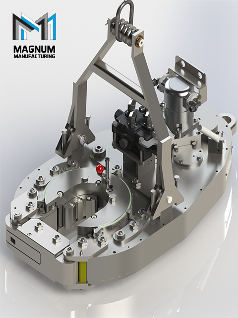
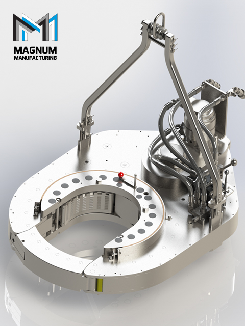
power tong mark 5 factory
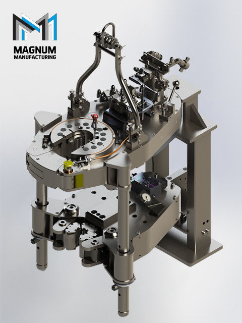
2018 marks the 60th anniversary for Eckel. We are the oldest continuous leading manufacturer of world-class hydraulic power tongs and trusted for reliability, safety and high performance.
Eckel 9-7/8 HS-55 Tubing / Casing providing high torque and high continuous rotational torque that you can trust within a compact operational footprint featuring SPACE SAVER™ technology.
Providing a maximum torque of 75,000 ft-lbs (101686 Nm) and 50,000 ft-lbs (67790.9 Nm) continuous rotational torque; well suited for today"s high torque premium casing connections.
The Eckel Model 25 Hydra-Shift® HS-85 features a two-speed motor with two-speed gear train, producing 60,000, 80,000 and 125,000 ft-lb of torque respectively in low-low, at 2,500 psi. This tong easily handles ultra-heavy casing strings from 9 5/8 inches to 25 inches.
The Eckel Model 25 Hydra-Shift® HT-200 Tri-Grip®introduced features a two-speed motor with two-speed gear train, producing 200,000 ft-lb of torque respectively in low-low, at 2,500 psi. This tong easily handles ultra-heavy casing strings from 9 5/8 inches to 25 inches - featuring a three head Tri-Grip®biting system design which like the Tri-Grip®New Revised Version Backup encompasses the tubular to apply an evenly distributed gripping force. The additional head in the tong reduces the risk of radial deformation, die penetration, marking, and wear of the tubular by 1/3 at extreme torques...
The new 7.25 HS HT-80 for Drill Pipe and High Torque Casing Tong takes on the toughest job with make-up and break-out of drill pipe, drill collars and high torque casing with a maximum torque of 80,000 ft-lbs. The 7.25 HS HT-80 is available with a two-speed Hydra-Shift® motor coupled with a two-speed gear train providing (4) torque levels and (4) RPM speeds. The variable speeds can slowly or quickly spin tubulars 2-3/8 through 7 1/4 inch as necessary. Having exceptional gripping capabilities with rig dies for drill pipe or wrap-around dies that securely encompass the tubular limit potential for damage. The 7.25 HS HT-80 is also available with either Eckel Pyramid Fine Tooth dies or True-Grit dies. The 7.25 HS HT-80 is another of our tongs models that exceeds the competition in its class.
Extremely popular among the most successful of pipe handlers, the Model 5 1/2 UHT combines high torque (up to 25,000 ft-lbs) with a wide capacity range. Ideal for handling tubing, casing and small drill pipe. Options include manual backup or Tri-Grip®backups.
The Eckel Model 14 Hydra-Shift® handles pipe from 4 inches to 14 inches and incoporates the Hydra-Shift® technology which provides smoother operating environment and a wider selection of torque/RPM"s that are available to the operator. The 14 Hydra-Shift® is capable of delivering 35,000 ft-lb of torque in low-speed, low-gear. Also available with hydraulic Tri-Grip®backup.
The Eckel Model 30 Hydra-Shift® features a two-speed motor with a two-speed gear train, producing 130,000 ft-lb of torque in low-low at 2,500 psi. Weight 9,000 pounds, this tong easily handles ultra heavy casing strings from 14 inches to 30 inches.
The Eckel Model 14 Hydra-Shift® handles pipe from 4 inches to 14 inches and incoporates the Hydra-Shift® technology which provides smoother operating environment and a wider selection of torque/RPM"s that are available to the operator. The 14 Hydra-Shift® is capable of delivering 35,000 ft-lb of torque in low-speed, low-gear. Also available with hydraulic Tri-Grip®backup.
Except for added torque (up to 24,000 ft-lb) and expanded pipe capacity (from 4 to 13 3/8 inches), the 13 3/8 Standard tong offers the same basic engineering and design as the smaller, lighter Model 10 3/4. Highly recommended where applications demand the ultimate in size range and torque output.
For casing up to 22 inches, here"s a tong that has strong torqueing ability and will handle pipe sizes down to 7 inch. The tong utilizes a two-speed motor and a two-speed gear train, allowing the operator to correctly adjust the tong for the optimum torque and RPM needed for the current application. Maximum torque for the 22 Hydra-Shift® is 80,000 ft-lb.
For casing up to 20 inches, here"s a tong that combines surprising speed with an ability to handle smaller sizes economically (as small as 7 inches). The 20 Standard reaches peak efficiency at just 38 horse power input, thus requiring no "souped-up" power unit. Available torque: 42,000 ft-lb.
An excellent choice where applications demand the combination of size range and high torque output, the Eckel Model 14 UHT handles pipe from 4 inches to 14 inches. Upgraded in design and performance over the Model 14 HS, this tong is capable of delivering 65,000 ft-lb of torque. Also, available with Wedge Drive Tri-Grip®backup which handles pipe from 4 inches to 15.5 inches.
When application demand a wide range of sizes, this tong handles pipe sizes 2 3/8 inches all the way to 7 5/8. Built around the 7 5/8 Standard, the 7 5/8 HS HD provides a thicker rotary gear for more added strength, an additional idler gear, a larger pinion gear, and stronger bearings for load bearing capacity and durability.
When application demand a wide range of sizes, this tong handles pipe sizes 2 3/8 inches all the way to 7 5/8. Built around the 7 5/8 Standard, the 7 5/8 Heavy Duty provides a thicker rotary gear for more added strength, an additional idler gear, a larger pinion gear, and stronger bearings for load bearing capacity and durability.
The Eckel Model 25 Hydra-Shift® features a two-speed motor with two-speed gear train, producing 60,000 ft-lb of torque in low-low, at 2,500 psi. Weighing 6,290 pounds, this tong easily handles ultra-heavy casing strings from 9 5/8 inches to 25 inches.
A maximum torque up to 25,000 ft-lb and a small foot print design this tong meets your application requirements. A two speed mechanical shift transmission in conjunction with the two speed Hydra-Shift® motor provides the operator a flexible choice of torque and rpm"s to work with during make-up or breakout. The 9 5/8 Hydra-Shift® HD is capable of handling a range of pipe from 2 3/8 inches to 9 5/8 inches.
Extremely popular among the most successful of pipe handlers, the Model 5 1/2 UHT combines high torque (up to 25,000 ft-lbs) with a wide capacity range. Ideal for handling tubing, casing and small drill pipe. Options include manual backup or Tri-Grip®backups.
The Eckel 870 DPT combine power tong and Wedg Drive Tri-Grip®Backup, providing a single piece of equipment to replace several...one smooth continuous operation instead of numerous time-wasting steps at each connection...and a quick, safe means of tripping, replacing methods that endanger crew members and pipe string a like. For drill strings up to 8 inch collars, the model 870 offers over 75,000 ft-lb of torque for break-out and make-up operations, plus ample speed for spinning joints.
The Eckel Model 24 UHT features a two-speed motor with single-speed gear train, producing 95,000 ft-lb of torque in low speed, 25,000 ft-lb in high, both at 2,500 psi. Weighing 8,000 pounds, this tong easily handles ultra-heavy casing strings from 13 3/8 inches to 24 inches.
Except for added torque (up to 24,000 ft-lb) and expanded pipe capacity (from 4 to 13 3/8 inches), the 13 3/8 Standard tong offers the same basic engineering and design as the smaller, lighter Model 10 3/4. Highly recommended where applications demand the ultimate in size range and torque output.
An excellent choice where applications demand the combination of size range and high torque output, the Eckel Model 14 UHT handles pipe from 4 inches to 14 inches. Upgraded in design and performance over the Model 14 HS, this tong is capable of delivering 65,000 ft-lb of torque. Also, available with Wedge Drive Tri-Grip®backup which handles pipe from 4 inches to 15.5 inches.
When applications require the combination of size and torque up to 18,000 ft-lbs, the Eckel 9 5/8 Hydra-Shift® (Narrow Body) meets these requirements. The narrow body design allows this tong to easily operate on smaller rig configurations. A two speed mechanical shift transmission in conjunction with the two speed Hydra-Shift® motor provides the operator a flexible choice of torque and RPM"s to work with during make-up or breakout. The 9 5/8 Hydra-Shift® is capable of handling a range of pipe from 2 3/8 inches to 9 5/8 inches.
When applications require the combination of size and torque up to 18,000 ft-lbs, the Eckel 9 5/8 Hydra-Shift® (Narrow Body) meets these requirements. The narrow body design allows this tong to easily operate on smaller rig configurations. A two speed mechanical shift transmission in conjunction with the two speed Hydra-Shift® motor provides the operator a flexible choice of torque and RPM"s to work with during make-up or breakout. The 9 5/8 Hydra-Shift® is capable of handling a range of pipe from 2 3/8 inches to 9 5/8 inches.
The 14 HS HT Tri-Grip®Tong is used for making up and break out casing and risers. Capable of handling tubulars from 4 in. to 14 in. (101.6 - 355.6 mm) in diameter with a maximum torque of 135,000 ft-lbs (183035.4) of torque capacity. A two-speed Hydra-Shift® motor coupled with a two-speed gear train provides (4) torque levels and (4) RPM speeds. The tong features a three head - Tri-Grip®biting system design which like the Tri-Grip®Backup encompasses the tubular to apply an evenly distributed gripping force. The additional head in the tong reduces the risk of radial deformation, die penetration, marking, and wear of the tubular by 1/3 at extreme torques. The tong performs exceptional gripping capabilities with either Eckel True-Grit dies or Pyramid Fine Tooth dies.
The Eckel Top Drive Casing Tong is a tool developed for use on hydraulic top drive rigs to provide a high quality connection while reducing tubular damage and providing a safer enviroment for crews. With an operating capacity of 4 1/2 inch through 10 5/8 inch, is connected to the output stem of the power swivel. After installation the tong becomes an integral part of the swivel, raising and lowering as a unit and transfering the power swivel"s RPM and torque to the pipe/connection. A guide attached beneath the top drive tong simplifies alignment of the collar within the tong. Once the collar of the pipe is enclosed within the top drive tong, the tong will grip the collar by operating the power swivel. Torque and rotational speed are controlled through the operation of the power swivel. Reversal of the power swivel will cause the tong jaws to release. Tong jaws are spring loaded to retract away from the collar. Utilizing three gripping jaws and a patented Eckel Cam Biting System to grip the pipe collar. The same type of proven biting system found in the industry leading Eckel Power Tongs. These jaws are spaced evenly about the circumference of the collar to provide even distribution of the gripping forces
The Oil & Gas Industry has needed a specialized power tong with an integral backup. This tong is sized small enough and has the right amount of controlable torque output. It is designed so as to properly grip small tubulars such as small macaroni type strings of tubing.
This tong incorporates Eckel"s Hydra-Shift® technology for smooth tranfers of power and speed directly to the tubular. Special built in torque control valving allows the operator to pre-set the maximum desired torque for the connection. This tong also incorporates our new Radial Lock Door. If you are looking for a tong for this lighter type of word look no further.
Except for added torque (up to 24,000 ft-lb) and expanded pipe capacity (from 4 to 13 3/8 inches), the 13 3/8 Standard tong offers the same basic engineering and design as the smaller, lighter Model 10 3/4. Highly recommended where applications demand the ultimate in size range and torque output.
An excellent choice where applications demand the combination of size range and high torque output, the Eckel Model 14 UHT handles pipe from 4 inches to 14 inches. Upgraded in design and performance over the Model 14 HS, this tong is capable of delivering 65,000 ft-lb of torque. Also, available with Wedge Drive Tri-Grip®backup which handles pipe from 4 inches to 15.5 inches.
When applications require the combination of size and torque up to 18,000 ft-lbs, the Eckel 9 5/8 Hydra-Shift® (Narrow Body) meets these requirements. The narrow body design allows this tong to easily operate on smaller rig configurations. A two speed mechanical shift transmission in conjunction with the two speed Hydra-Shift® motor provides the operator a flexible choice of torque and RPM"s to work with during make-up or breakout. The 9 5/8 Hydra-Shift® is capable of handling a range of pipe from 2 3/8 inches to 9 5/8 inches.
Extremely popular among the most successful of pipe handlers, the Model 5 1/2 UHT combines high torque (up to 25,000 ft-lbs) with a wide capacity range. Ideal for handling tubing, casing and small drill pipe. Options include manual backup or Tri-Grip®backups.
An excellent choice where applications demand the combination of size range and high torque output, the Eckel Model 14 UHT handles pipe from 4 inches to 14 inches. Upgraded in design and performance over the Model 14 HS, this tong is capable of delivering 65,000 ft-lb of torque. Also, available with Wedge Drive Tri-Grip®backup which handles pipe from 4 inches to 15.5 inches.
When application demand a wide range of sizes, this tong handles pipe sizes 2 3/8 inches all the way to 7 5/8. Built around the 7 5/8 Standard, the 7 5/8 Heavy Duty provides a thicker rotary gear for more added strength, an additional idler gear, a larger pinion gear, and stronger bearings for load bearing capacity and durability.
Compact Size...Big Torque...if this is what you are looking for in a power tong, look no further. Our 5-1/2 Hydra-Shift® is sized smaller in width than our 5-1/2 Standard model. Like all of our newly developed tongs, the 5-1/2 incorporates the Hydra-Shift® technology, allowing the operator to shift from high speed to low speed without having to manually shift the tong. You will see many years of trouble free operation, not to mention the smoother hydraulic shifting. With two models to choose from, Eckel has the right 5-1/2 Hydra-Shift® for your needs. The 5-1/2 Hydra-Shift® LS with a two-speed motor and a single-speed gear train is the original 5-1/2 Hydra-Shift® which has gained wide acceptance in the industry. Slide heads with rig dies are available for handling drill pipe tool joints.
Special applications and tough requirements demanded that we respond with a new tong designed and built with today"s pipe handling challenges in mind, the 8 5/8 Hydra-Shift® HT. By utilizing a two speed mechanical shift transmission in conjunction with the two speed Hydra-Shift® motor, the operator has a more flexible choice of torque/RPM"s to work with during make-up or break-out. At the beginning of the job, the operator will choose a tong gear ratio that is most appropriate for the current tubular connection and shift the variable speed motor handle into high or low as required. This tong also offers sliding heads with wrap-around dies which provides an evenly applied pressure to the pipe and a greater pipe gripping coverage which in return reduce tubular damage. This tong not only offers the operator the speed options down to the slow speed parameter now demanded by the pipe manufactures and oil companies, it also has the option of speeds of 100 RPM"s when required. Available torque: 40,000 ft-lb
When application demand a wide range of sizes, this tong handles pipe sizes 2 3/8 inches all the way to 7 5/8. Built around the 7 5/8 Standard, the 7 5/8 Heavy Duty provides a thicker rotary gear for more added strength, an additional idler gear, a larger pinion gear, and stronger bearings for load bearing capacity and durability.
When higher torque performance than 10 3/4 Standard is required, the Eckel 10 3/4 Heavy Duty provides the performance you need. Model 10 3/4 Heavy Duty is always in demand where rig floor space is at a minimum. For pipe sizes from 4 to 10 3/4 inches, it delivers a stout 25,000 ft-lb of available torque.
Eckel Tri-Grip®an industry standard for reliable backup in make-up and break-out of tubular connections and optionally supplied with Eckel tongs. Eckel backups utilize hydraulic cylinders and a head arrangement that insures slip-free operation. The hydraulic backup is suspended at an adjustable level below the power tong by means of three hanger legs and allowing the backup to remain stationary while the power tong moves vertically to compensate for thread travel of the connection. The Tri-Grip®uses two pivoting heads and one stationary while the cam backup uses two head to grip tubulars using a head and cam configuration that is similar to the method the tong grips tubulars.
The Eckel Closed Mouth Tongs uses three sliding heads with each head equipped with a wide angle wrap-around die. This provides a maximum gripping area of 342 degrees; on the pipe. The CMT"s utilizes the Hydra-Shift® shifting technology which allows the operator to shift from high to low speed without stopping the tong. Reversing the pipe rotation is effortless and done simply by pulling the tong control in the opposite direction. There is no need to physically take out the jaws and turn them over as there is with other brands of closed head tongs. The CMT"s also come with an optional backup that utilizes the same heads/dies as the tong.
The Model 4 1/2 UHT-13 is rugged, light weight tong capable of providing 8,500 ft-lb of torque at 2,500 PSI. The tong will handle pipe from 1.050 inches to 4 1/2 inches. A notable feature is the Eckel patented quick-change sliding head biting system that compensates for worn or under gauge pipe. Also available with an optional rod package for sizes 5/8 inch through 1-1/8 inches and your choice of manual type or hydraulic type backups.
For casing up to 17 inches, here"s a tong that combines speed and the ability to handle smaller sizes economically. If you are running 17 inch casing, give this tong a try. The 17 Hydra-Shift® features the two-speed motor and the two-speed gear train which allows for multiple selections of torque or RPM, not to mention the smoother operation of the tong.
The Eckel Model 14 Hydra-Shift® handles pipe from 4 inches to 14 inches and incoporates the Hydra-Shift® technology which provides smoother operating environment and a wider selection of torque/RPM"s that are available to the operator. The 14 Hydra-Shift® is capable of delivering 35,000 ft-lb of torque in low-speed, low-gear. Also available with hydraulic Tri-Grip®backup.
The Eckel 3500 Hydra-Shift® DTT (Dual Tubing Tong) provides fast, easy running on dual strings of 3 1/2 inch or smaller tubing. It grabs from the side, or head-on. Go ahead and torque it up; this tong is Eckel tough. And speed shifts are no problem, thanks to a patented Hydra-Shift® concept that eliminates clutching. The Model 3500 DTT Hydra-Shift® is packed with all the features you"ve come to expect from Eckel: quick-change sliding heads, self-aligning open throat.
Except for added torque (up to 24,000 ft-lb) and expanded pipe capacity (from 4 to 13 3/8 inches), the 13 3/8 Standard tong offers the same basic engineering and design as the smaller, lighter Model 10 3/4. Highly recommended where applications demand the ultimate in size range and torque output.
The big, capable Model 36 UHT easily produces 100,000 ft-lb of torque for makeup or break-out operations involving casing in sizes 16 inches through 36 inches. Weighing approximately 13,000 pounds, this casing tong is 81 inches wide and 135 inches in length. A two-speed motor delivers 16 RPM in high, 3 1/2 RPM in low range, both at 70 GPM.
The Eckel 870 DPT combine power tong and Wedg Drive Tri-Grip®Backup, providing a single piece of equipment to replace several...one smooth continuous operation instead of numerous time-wasting steps at each connection...and a quick, safe means of tripping, replacing methods that endanger crew members and pipe string a like. For drill strings up to 8 inch collars, the model 870 offers over 75,000 ft-lb of torque for break-out and make-up operations, plus ample speed for spinning joints.
Eckel has been at the forefront of this developing technology with the development of larger wrap-around type dies for many of its tong models. Wrap-Around Dies are symmetrically spaced from each other at all times insuring an equally distributed load on the tubular.
An excellent choice where applications demand the combination of size range and high torque output, the Eckel Model 14 UHT handles pipe from 4 inches to 14 inches. Upgraded in design and performance over the Model 14 HS, this tong is capable of delivering 65,000 ft-lb of torque. Also, available with Wedge Drive Tri-Grip®backup which handles pipe from 4 inches to 15.5 inches.
The Model 5 1/2 Standard is the first open-throat design in its size range to generate 12,000 ft-lb of available torque. Versatility is the name of the game here as this tong works well whether powered by a workover rig or a portable casing tong power unit. Options include manual backup or cam-type hydraulic backups.
Extremely popular among the most successful of pipe handlers, the Model 5 1/2 UHT combines high torque (up to 25,000 ft-lbs) with a wide capacity range. Ideal for handling tubing, casing and small drill pipe. Options include manual backup or Tri-Grip®backups.
When applications demand a wide range of sizes, the 7-5/8 Standard tong handles pipe sizes 2-1/16 inches all the way to 7-5/8. Its rugged design is based upon knowledge gained from the 5-1/2 model...combining an extremely compact, high torque concept with added versatility. Options include either manual backup or Tri-Grip®backup. Available torque: 15,000 ft-lb
For casing up to 20 inches, here"s a tong that combines surprising speed with an ability to handle smaller sizes economically (as small as 7 inches). The 20 Standard reaches peak efficiency at just 38 horse power input, thus requiring no "souped-up" power unit. Available torque: 42,000 ft-lb.
The Eckel Model 24 UHT features a two-speed motor with single-speed gear train, producing 95,000 ft-lb of torque in low speed, 25,000 ft-lb in high, both at 2,500 psi. Weighing 8,000 pounds, this tong easily handles ultra-heavy casing strings from 13 3/8 inches to 24 inches.
This invention is directed to apparatus and methods for aligning wellbore tubulars; and to power tongs used in making and breaking joints of tubular members such as wellbore casing and tubing; to parts thereof; including, but not limited to gripping elements, and methods of their use.
During the drilling of oil and gas wells and the production of materials therefrom, various operations require the connection and disconnection of successive lengths of threaded tubulars such as pipe, casing, or tubing. Tools known as tongs are used to "make" and "break" such connections. Certain known power tongs have a body, a rotary rotatably mounted in said body and at least one active jaw which, on rotation of the rotary is cammed against a pipe in the rotary and grips it for rotation with the rotary. In known arrangements the camming action is generated by a cam member which is bolted to the rotary and is shaped so that the active jaw is cammed against the pipe on rotation of the rotary relative to the active jaw in one sense and will be released on rotation of the rotary relative to the active jaw in the opposite sense.
With known tongs high torques are applied to tubulars due to combinations of factors such as thread sealing requirements, the presence of corrosion, the existence of distortion, and pipe size and weight. Both in the "make" direction of rotation when a shoulder is suddenly encountered, and in the "break" direction at initial engagement of the tong and disengagement of the threads high shock forces may arise; e.g., with a power-driven tong, in excess of 50,000 foot-pounds of torque may be exerted, while relatively small die elements on jaws of the tong engage the pipe with extremely high force loadings. Slippage occurs and pipe surfaces become marred, marked, indented, or otherwise damaged.
Dies for gripping jaws have been provided with multiple serrations, or penetration features, to provide the interference contact at the joint surface. Grip element penetration into the joint surface is limited and controlled. The distribution and balance of grip element energizing forces are critical factors in the design, development and evaluation of such tong mechanisms. Linkages, levers, wedges, and cams are used to balance force components. Grip elements, or dies, are accurately disposed within carrier bodies, or jaws, which span a circumferential segment of the joint surface.
Uneven die loading can cause excessive indentation, marring or damage to a tubular surface. Drag or braking devices are used in certain tongs to effect proper biting of the dies relative to the pipe. The head or other member supporting the dies is frictionally restrained to insure that the dies do not simply rotate with the rotary as the rotary is driven.
Other tongs use an endless belt, chain or flexible material loop for gripping a tubular. Such tongs are disclosed in U.S. Pat. Nos. 3,799,010; 3,906,820; 3,892,140; 4,079,640; 4,099,479; and 4,212,212. There are a variety of problems associated with certain of these tongs:
Jaw/die tongs and the belt/chain tongs are used with relatively hard and rigid metal tubulars such as casing and tubing. If these tongs are used with thick tubulars or tubulars made from relatively "softer" metals or from premium metals such as high alloy steels or low carbon steels or tubulars made from non-metal materials such as fiber glass, they often literally chew up the tubular. The use of strap wrenches is inadequate since the torque applied with such wrenches cannot be precisely controlled.
Certain tubulars are treated with a rust or corrosion resistant material or coating. If the coating is indented, gouged, or broken, its protective purpose is defeated. Producing enough force in a tong to join such tubulars while not injuring a protective coating presents a dilemma.
The present invention, in certain embodiments, discloses a power tong for joining tubulars so that marking of, indentation of, and surface injury to tubulars are reduced or eliminated. In one aspect a power tong is provided and a method of its use for handling tubulars coated with a corrosion-resistant material which should not be broken or penetrated. In one embodiment such a tong has one or more gripping jaws with gripping elements made of aluminum alloys, zinc, zinc alloys, aluminum, brass, bronze, cermet, plastic, fiberglass, metal alloys, or a combination thereof which present a smooth face (straight or curved) to a tubular without any teeth, pointed projections, or toothed dies. In one aspect the gripping elements are releasably connected directly to jaws. In another aspect the gripping elements are releasably connected to a jacket or holder which itself is releasably connected to a jaw.
In one aspect the cylinder(s) are powered by a small air-driven hydraulic pump with an hydraulic fluid reservoir mounted on a plate on the movable or fixed jaw. Air is supplied to activate a motor of the pump and the pump then provides hydraulic fluid to move a piston of the hydraulic cylinder(s). The motion of the cylinder moves the movable jaw on its roller to travel to a pre-load position on the cam. The cylinder applies pressure until the hydraulic pressure is released. A hydraulic fluid accumulator and a valve may be used to maintain hydraulic pressure at all times so that the cylinder(s) continuously maintain the desired load on the jaw until the air supply to the pump is removed.
In another aspect the cylinders are connected to a rotary of the tong or to any other member that rotates with the rotary rather than to a fixed jaw. Such a pre-load system may, according to this invention, be used with any tong including a tong that does use toothed dies.
In one embodiment the present invention discloses a gripping arrangement for a tong with a sheet of grit which is preferably bonded to a carrier plate. In another embodiment the gripping arrangement comprises a layer of flexible material having a smooth flat surface or a surface with ridges and valleys, for example in the fashion of the surface of a file. The flexible material, in one aspect, is metal, for example sheet aluminum, zinc, brass, bronze, zinc alloy, aluminum alloy, stainless steel, or steel having a thickness of about 1.5 mm. The layer of flexible material may be used in conjunction with a carrier plate or on its own. In a further embodiment the gripping arrangement may comprise a layer of perforate material one of both surfaces of which are preferably coated with grit to facilitate adhesion. The layer will typically be formed from metal having a thickness of about 1.5 mm. The layer may be used in conjunction with a carrier plate or used on its own. In yet another embodiment the gripping arrangement may comprise a layer of expanded mesh, e.g. metal mesh, which has been flattened. One or both surfaces of the expanded mesh may be coated with grit and the layer may be used in conjunction with a carrier plate or used on its own. The grit may comprise, for example, diamond dust, particles of silicon, zircon, tungsten carbide and mixtures thereof. The gripping arrangement may comprise end plates which are attached to the carrier plate. Preferably, the carrier plate is provided with side flanges for insertion into a jaw holder. The present invention also provides a jaw assembly fitted with a gripping arrangement in accordance with the present invention. Preferably, the jaw assembly includes a jaw holder having an arcuate recess which accommodates an arcuate pad of resilient elastomeric material which supports said gripping arrangement. Advantageously, at least one shim is provided which is disposed between said arcuate pad of resilient elastomeric material and said gripping arrangement. The shim will be flexible and generally from 0.5 mm to 1.0 mm thick and made from sheet metal. The present invention also provides a tong fitted with at least two such jaw.
In one embodiment the present invention discloses an apparatus for aligning tubulars and includes a guide on one of a power tong and a backup tong. In one embodiment the apparatus has a socket centralizer mounted on said one of said power tong and said backup tong. In one aspect, said one of said power tong and said backup tong is said power tong. In another embodiment, the apparatus includes a power tong and a backup tong, and the guide is mounted on the power tong and apparatus is provided to maintain the power tong and the backup tong in a certain juxtaposition during a stabbing operation. Preferably, said apparatus includes locating rods on one of the power tong and the backup tong and blocks shaped to receive at least the ends of the locating rods on the other of the power tong and the backup tong. Advantageously, the backup tong is provided with at least two prismatic jaw assemblies to locate the backup tong in fixed juxtaposition with respect to a tubular being gripped.
The present invention, in one aspect, provides a jaw unit for use in a tong, which jaw unit comprises a jaw holder and a jaw movable with respect to said jaw holder, characterized in that said jaw is slidably mounted on said jaw holder. Preferably, said jaw is slidable with respect to said jaw holder about an arcuate path. Advantageously, said jaw has a gripping surface which is substantially arcuate for gripping the surface of a tubular and the center of curvature of such arcuate path lies between the center of curvature of said grip ping surface and said arcuate path. The gripping surface may be a continuous surface or defined by several spaced apart gripping elements. Preferably, the center of curvature of said arcuate path lies between the center of curvature of said grip ping surface and said gripping surface. Advantageously, the center of curvature of said arcuate path is substantially midway between the center of curvature of said gripping surface and said gripping surface. Preferably, one of said jaw and said jaw holder is provided with an arcuate track which defines said arcuate path, and the other of said jaw and said jaw holder is slidably mounted in said arcuate track.
The present invention also provides a jaw assembly comprising two jaw units in accordance with the present invention. Preferably, said jaw units are mounted for pivotal movement about a common pivot shaft. Advantageously, said jaw assembly includes means which bias said jaw units apart. The present invention also provides a rotary fitted with a jaw unit in accordance with the present invention, a rotary fitted with a jaw assembly in accordance with the present invention, and a tong fitted with a rotary in accordance with the present invention.
One of the features of existing tongs is that their rotaries are difficult to furnish. Thus, routine maintenance usually involves dismantling the whole rotary, checking the parts and reassembling the whole. While this is a straightforward procedure in the clean conditions of a workshop it can be problematic when carried out in a muddy field, in sand or in snow. The present invention aims to help solve this problem and provides a rotary which comprises a top section, a bottom section, and a peripheral wall therebetween, characterized in that at least one of said top section and said bottom section is provided with an elongate slot which, when said rotary is in use, accommodates a pivot shaft on which a jaw assembly can be pivotally mounted.
Jaw holders and jaws for tongs are traditionally machined from a solid piece. This is a comparatively expensive procedure. The present invention proposes to make such parts from a stack of individually cut laminations.
Such methods and devices including a power tong with at least one jaw with at least one tubular gripping element having a smooth gripping surface (flat or curved) and, in one aspect, such an element which is flexible;
FIG. 2A is a perspective view of a tubular connection system according to the present invention. FIGS. 2B and 2C are perspective views of a casing tong of the system of FIG. 2A.
FIG. 5A shows schematically an initial position of elements of a tong system according to the present invention. FIG. 5B shows pre-loading on a pipe of the jaws of the system of FIG. 5A. FIG. 5C shows a tubular gripped with the system of FIG. 5A.
FIGS. 1A-1C show a typical prior art power tong that uses fixed jaws and a movable jaw to grip pipe for tubular disconnecting and connecting operations. An outer case houses a powered rotary to which the jaws are mounted. A cam surface of the rotary moves a movable (ACTIVE or MASTER) jaw into (and away from) gripping contact with a tubular, e.g. pipe. Each jaw has toothed gripping inserts to facilitate engagement with the surface of the tubular (see FIG. 1B). FIG. 1C shows the tong in an "OPEN" position in which the tubular is not gripped.
The tong shown in FIG. 1A is a Weatherford Model 14.5-50 High Torque Tong. The brochure "New ! Weatherford Model 14.5-50 High Torque Tong," (1991) and the manual entitled "Model 14.5-50 Hydraulic Power Tong Installation, Operation and Maintenance" (1993) are submitted herewith and incorporated herein fully by reference for all purposes. It is to be understood that the teachings of the present invention are applicable to any tong and any tong system that has one or more gripping elements or jaws and that the Model 14.5-50 tong is shown here for illustrative purposes and not by way of limitation of the scope of the present invention.
As shown in FIG. 2A a system 10 according to the present invention includes a power tong 100 according to the present invention which is like the tong of FIG. 1A but which also includes a unique jaw system 110 with inserts 150 on fixed jaws 120 and insert 152 on movable jaw 122 and at least one jaw pre-load assembly like that shown in FIG. 5A. The system 10 includes a free floating backup tong 12.
As shown in FIGS. 2B and 2C, rods 112 are connected to the movable jaw 122. The inserts 150 are on fixed jaws 120 and the insert 152 is on a movable jaw 122 (corresponding to the fixed jaws and active jaw, respectively, of the tong of FIG. 1A).
Stops 124 hold jaws 120 and prevent sideways insert movement. The stops 124 may be welded to the jaw or otherwise secured. Removable bolts may be used instead of the stops 124. The stops 126 perform the same functions. A right angled member 127 (FIG. 3C) maintains a roller 135 rotatably in place in holes 123, 125. Holes 129 either receive a projection of an insert to maintain the insert in place or a pin extends through the hole 129 into the insert to accomplish this.
FIGS. 4A-4G illustrate an alternative jaw mounting system in which holders are interposed between jaw bodies and inserts. The holders protect the jaws from damage if the inserts wear down and a variety of different types and/or sizes of inserts may be used with and interchanged on a single holder. In one aspect it is within the scope of this invention to use these holders to mount conventional toothed dies to a tong jaw and to use them for easy substitution of new and/or different dies.
FIG. 4A shows a jaw system 400 for a tong (like the tong of FIG. 2A) which has two fixed jaws 402 and a movable (movable toward and away from a tubular to be gripped 403) jaw 404. Each jaw 402 has a jaw body 405 with a holder 406 secured thereto. In one aspect dovetail keys 407 secured to the holder or releasably mounted thereto fit in corresponding slots 408 of the jaw bodies 405 to releasably mount the holder 406 to the body. In one aspect dovetail keys 409 releasably mount the holders 406 to jaw bodies 405. The dovetail keys 409 are releasably held in corresponding recesses 411 in the holders 406. One or more dovetail keys 409 may be used (two shown for each holder 406).
An insert 420 has dovetail keys 421 received and held in corresponding slots 422 of the holder 414. The insert 420 is shown as a single unitary insert but a plurality of individual inserts (either abutting or spaced apart) may be used secured to the jaw body 415.
FIG. 5A shows a tong system 500 with a tong having a movable rotary 502, fixed jaws 504, 505, and a movable jaw 506 (remainder of tong, not shown, like the tong of FIG. 2A; like the tong of FIG. 1A, but with the added features discussed here). Pins 520 pin the fixed jaws to the rotary. Inserts 522 on the fixed jaws 504, 505 are like the inserts described herein for other fixed jaws. Insert 524 on the movable jaw 506 is like other inserts described herein for movable jaws. A pre-load cylinder 508 to assist in make-up is pivotably connected at one end to the fixed jaw 505 and at the other end to the movable jaw 506. A pre-load cylinder 510 to assist in break-out is pivotably connected at one end to the fixed jaw 504 and at the other end to the movable jaw 506. It is within the scope of this invention for the ends of cylinders connected to the fixed jaws to instead be secured to the rotary or to a support ring or other member that rotates with the rotary. It is within the scope of this invention to employ one cylinder interchangeable between the positions of the cylinders 508 and 510 (FIG. 5A) or one cylinder connectible to the fixed jaw 506 at one end for break-out and at the other end of the fixed jaw 506 for make-up with the other cylinder end secured to the rotary. Rollers 530 rotatably mounted on the movable jaw 506 co-act with cam surfaces 532 on the rotary 502 to move the jaw 506 to operative and inoperative positions.
A bleed valve 620 functions to selectively release pressure from the pre-load cylinders following make-up or break-out. A pump 630 pumps hydraulic fluid from the reservoir 608 to a line 631, in a line 632 to the accumulator 610, in a line 633 to the directional control valve 602, and in lines 634 and 635 to (and from) the pre-load cylinders 508 and 510. A check valve 638 in a line 637 from the reservoir 608 prevents fluid from flowing back into the reservoir. A check valve 639 in the line 631 insures that the pump 630 pumps fluid only from the reservoir and prevents fluid from the cylinder 508, 510 and/or from the accumulator 610 from flowing back to the pump 630 and to the reservoir 608.
Air in a line 640 selectively applied with a control system 650 (e.g. mounted on the rig floor, on the tong or remote controlled) selectively actuates the pump 630 to pump fluid through the valve 602 to the pre-load cylinders. The directional control valve 602 is either manually operated or operated by remote control. Correct fluid pressure is monitored with a gauge 651.
As shown in FIG. 5B, the system 500 is being pre-loaded for gripping a tubular 650. Fluid is applied into the pre-load cylinder 508 to overcome a spring force of a spring 551 and allow a piston 552 to move the movable jaw 506 away from the fixed jaw 505. The directional control valve 602 is set to permit fluid to be pumped in the line 634 to the pre-load cylinder 508.
Simultaneously fluid is flowing out in line 635 from the pre-load cylinder 510, allowing its spring 553 to urge its corresponding piston 554 inward into the pre-load cylinder 510 thereby pulling the end of the movable jaw toward the fixed jaw 504 and increase the loading of the jaw 506 on the tubular 650.
As shown in FIG. 5C the tubular 650 has been gripped due to the action of the pre-load cylinder 510 with a suitable pre-load force (e.g., but not limited to, about 500, 1000, 5000, 10000 or 50000 pounds of force). This force is sufficient that when the rotary 502 of the tong is rotated the jaws do not slip on the tubular 650; but the pre-load force is sufficiently low that the jaws do not mark or damage the tubular 650.
FIG. 8 shows schematically a top view of a power tong according to the present invention. A power tong T has an hydraulic motor M with control/monitor apparatus C on a tong case S. A movable jaw J is moved and rotated by a rotary R which is moved by interconnection, via appropriate gearing, by the motor M. Fixed jaws F and G are secured to the rotary R. A first pre-load cylinder D connects the movable jaw J to the fixed jaw G for applying a pre-load to the movable jaw for make-up operations. A second pre-load cylinder L connects the movable jaw J to the fixed jaw F for applying a pre-load to the movable jaw for break-out operations. An insert I (any insert disclosed herein) is secured to the movable jaw J and inserts K (any insert disclosed herein) are secured to the fixed jaws F and G.
FIG. 9 shows a tong jaw 450 according to the present invention with an insert 454 (any insert disclosed herein) and rods 452 secured thereto, e.g. by welding. The rods 452 provide a member to which either a cylinder body or a piston of a pre-load piston cylinder apparatus is connectible. Instead of the rods 452 as shown which extend from above the jaw 450 to a point below it, only rod sections may be used secured to one or both sides of the jaw to provide a securement member for an end of a pre-load apparatus.
According to the present invention a variety of apparatuses and devices may be employed to pre-load a tong jaw having one or more smooth faced gripping insert elements thereon. In one aspect a manually activated pre-load cylinder is used which has fluid or material manually introduced therein to apply a pre-load or manually removed therefrom to release a pre-load. In another aspect a pre-load cylinder is pivotably secured at one end to a rotary or part thereof and the other end is releasably connectible to either end of a movable jaw so that a pre-load may be applied, selectively, to either end of the movable jaw for make-up or break-out operations as desired. In one aspect such a pre-load cylinder has a rod with an end member receivable in and movable in a slot in the movable jaw or there are recesses at either end of the jaw for holding the end member of the rod so that a pre-load can be applied. A secondary small cylinder may be used to selectively move the pre-load cylinder in the jaw slot or it can be moved manually. In another embodiment the tong"s movable jaw has one or more upwardly projecting lugs engageable by a forked piston rod end of a pre-load piston/cylinder that is attached to the rotary. The rotary is rotated so that the jaw is cammed into the pipe to be rotated in a pre-load position and then the forked rod is removed for further tong operations.
The jaw assembly 1001 comprises a jaw holder 1002 which is provided with an arcuate recess 1003 which accommodates an arcuate pad 1004 of resilient elastomeric material. A block 1005 of steel is molded into each end of the arcuate pad 1004 as shown. Three thin shims 1006 of metal each having a thickness of about 0.5 mm are positioned on the inner surface of the arcuate pad 1004 and support an insert or gripping arrangement 1007 which comprises a carrier plate 1008 and a friction layer 1009. The carrier plate 1008 has side flanges 1010 and 1011 which clip over the blocks 1005 as shown. The top and bottom of the carrier plate 1008 are tack welded to end plates 1012 and 1013 which are bolted to the jaw holder 1002 by socket screws 1014. The friction layer 1009 comprises a sheet of zircon paper which is bonded to the carrier plate 1008. The carrier plate 1008 is made of sheet steel and is approximately 1.5 mm thick. As such it is quite flexible.
In use, two or more jaw assemblies are placed in a tong and are disposed around a length of casing. The jaw assemblies 1001, 1001" are then advanced radially inwardly in the direction of arrows "A" (FIG. 12) until they engage and firmly grip the casing. Because of the flexible construction of the gripping arrangement 1007, the shims 1006 and the arcuate pad 1004, the friction layer 1009 substantially conforms to the circumference of the casing and grips the casing with a substantially uniform gripping action. Once the casing has been firmly gripped the jaws are rotated by the tong in the usual manner. It will be noted that circumferential forces applied to the friction layer are transmitted through the carrier plate 1008 so that any local loads caused, for example by an irregularity in the surface of the casing are redistributed by the carrier plate 1008 and transmitted to the jaw holder 1002 via the side flange 1011 and the arcuate pad 1004 (see FIG. 18).
Various modifications to the embodiment described are envisaged, for example the friction layer 1009 could comprise silica paper, carborundum paper, tungsten carbide paper, or diamond paper, the term "paper" as used herein including cloth. If desired the friction layer 1009 may comprise a layer of flexible material, for example metal, having a surface formed with ridges and valleys similar to the surface of a metal file. Such an arrangement is shown in FIG. 15 where the friction layer has been identified by reference numeral 1009". In this embodiment the friction layer could be bonded to the carrier plate. However, it is conceivable that the carrier plate could be dispensed with since the friction layer 1009" is capable of redistributing circumferential forces itself. If desired the blocks 1005 are disposed with, particularly if the arcuate pad 1004 is made from a relatively firm resilient elastomeric material. The shims 1006 may be dispensed with although they help prevent the resilient elastomeric material of the arcuate pad 1004 being extruded under pressure.
Referring to FIGS. 19A and 19B of the drawings there is shown a conventional tong assembly which is generally identified by the reference numeral 2001.
The power tong 2002 comprises a pair of gates 2004, 2005 which are held together in the position shown by latch 2006. When the latch 2006 is released the gates 2004, 2005 can be swung open by admitting hydraulic fluid to piston and cylinder assemblies 2007 and 2008. The power tong 2002 also contains a rotary 2009 which is provided with four jaw assemblies 2010. The rotary 2009 can be rotated by a hydraulic motor 2011.
The backup tong 2003 is provided with two gates 2012, 2013 which are held together by latch 2014 but which, when latch 2014 is released can be swung to an open position.
Once the pin is correctly located the stabbing guide is removed. The gates 2004, 2005 of the power tong 2002 and the gates 2012, 2013 of the backup tong 3 are then opened and the tong assembly 2001 moved towards the casing until the lower length of casing lies within the backup tong 2003 and the upper length of casing lies within the power tong 2002. The gates 2004, 2005, 2012, 2013 are then closed and latched. Jaw assemblies in the backup tong are then advanced to engage the lower length of casing while jaw assemblies in the power tong 2002 are advanced to grip the upper length of casing. The hydraulic motor 2011 is then actuated to turn the rotary 2009 and rotate the upper length of casing relative to the lower length of casing. The tong assembly 2001 is supported by a pneumatic lifting cylinder 2015 which enables the power tong 2002 to move towards the backup tong 2003 as the pin enters the socket. Reaction forces are transmitted by columns 2016 disposed to either side of the tong assembly 2001 and by a series of levers in a known manner. It should be noted that the power tong 2002 is free to move in a plane parallel to the backup tong 2003 within certain limits.
The apparatus 2100 comprises a tong assembly 2101 which is generally similar to the tong assembly 2001 shown in FIGS. 19A and 19B and parts of the tong assembly 2101 similar to the tong assembly 2001 have been identified by similar reference numerals in the "2100" series.
Turning first to the guide 2117 it will be seen from FIG. 21B that this comprises four identical components 2118 which are bolted to the top of the power tong 2102. As best shown in FIG. 21C each component is tapered so as to guide the pin of an upper casing to the center of the opening of the power tong 2102.
Referring now to FIG. 22, the backup tong 2103 is provided with three prismatic jaw assemblies 2119a, 2119b, and 2119c which, when actuated, hold a lower length of casing 2120 in a fixed position relative to the backup tong 2103.
As shown in FIG. 23 the backup tong 2103 is provided with three upwardly extending locating rods 2121 which are each provided with a conical tip 2122. Similar, the underside of the power tong 2102 is provided with three blocks 2123 each of which is provided with a recess 2124 shaped to receive the conical tip 2122 of a respective locating rod 2121.
In use, the lower length of casing 2120 is first secured by slips on the rig floor in the usual manner. The gates 2112 and 2113 of the backup tong 2103 are then opened and the tong assembly 2101 moved into position with the backup tong 2103 circumjacent the lower length of casing 2120 and immediately below the socket 2125 thereof.
The gates 2112 and 2113 are then closed by hydraulic piston and cylinder assemblies 2126 and 2127 and the latch 2114 closed. The prismatic jaw assembly 2119a is fixed while prismatic jaw assemblies 2119b and 2119c are automatically advanced by a predetermined distance when the latch 2114 is closed. This grips the lower length of casing firmly and also ensures that the backup tong 2003 is in a fixed position relative to the lower length of casing 2120. The position thus far attained is shown in FIG. 23.
At this time pneumatic lifting cylinder 2115 is extended which lowers the backup tong 2003. The conical tips 2122 of the locating rods 2121 enter the recesses 2124 of the blocks 2123 and thus locate the power tong 2002 with respect to the backup tong 2003. This in turn locates the guide 2117 with respect to the lower length of casing 2120 so that the center of the guide 2117 is coaxial with the axis of the lower length of casing 2120. This position is shown in FIG. 24.
At this time the upper length of casing 2128 is lowered into the proximity of the guide 2117. As shown in FIG. 25 the lower end of the upper length of casing 2128 is provided with a pin 2129 which is tapered.
As the upper length of casing 2128 is further lowered the pin 2129 enters the guide 2117 and is centered thereby. It then passes downwardly until it enters the socket 2125 as shown in FIG. 26.
The power tong 2102 is then raised so that the blocks 2123 are well clear of the locating rods 2121. At this point the jaw assemblies in the power tong 2102 are applied to the upper length of casing 2128 and the hydraulic motor 2111 actuated to rotate the rotary and screw the pin 2129 into the socket 2125. During the procedure the power tong 2102 moves towards the backup tong 2103. However, even when the joint is tightened to the required torque the blocks 2123 still lie a short distance above the conical tips 2122 of the locating rods 2121.
At this stage the jaw assemblies of both the power tong 2102 and the backup tong 2103 are relaxed, the gates 2104, 2105, 2112 and 2113 opened and the tong assembly 2101 retracted in preparation for the casing being lowered. It will be noted that one component 2118 of the guide 2117 is mounted on each of the gates 2104, 2105 and accordingly the guide 2117 opens and closes with the gates 2104, 2105.
For certain applications a backup tong is not required, for example where the power tong can conveniently be restrained by a chain attached to the drilling tower.
The apparatus 2200 comprises a power tong 2202 which is generally similar to the power tong 2002. The basic construction of the power tong 2202 is similar to the power tong 2002 and parts having similar functions have been identified by the same reference numeral in the "2200" series.
The main differences are that the apparatus 2200 does not include a backup tong and that it is provided with a guide 2217 and a socket centralizer 2230.
In use, the lower length of casing 2220 is first secured by slips (not shown) with the socket 2225 facing upwardly close to the slips. The power tong 2202 is then lowered onto the socket 2225 so that the socket 2225 enters the socket centralizer 2230 and aligns the socket centralizer 2230, the socket 2225 and the guide 2217. The upper length of casing 2228 is then lowered so that its pin 2229 enters the guide 2217, is center there by and enters the socket 2225. At this point power tong 2202 is raised. Its jaw assemblies are then advanced to grip the upper length of casing 2228 which is then rotated to screw the pin 2229 into the socket 2225. Once the joint is tightened to the required torque the gates 2204, 2205 are opened and the power tong 2202 withdrawn.
The embodiment shown in FIG. 29 is generally similar to that shown in FIG. 28 except that the apparatus 2300 also includes a backup tong 2303. Since the upper length of casing 2328 and the lower length of casing 2320 are being aligned by the guide 2317 and the socket centralizer 2330 no special arrangements need be made for aligning the power tong 2302 and the backup tong 2303.
The procedure for connecting the upper length of casing 2328 to the lower length of casing 2320 is as follows. First, the lower length of casing 2320 is secured in slip (not shown). The gates 2312, 2313 of the backup tong are then opened and the apparatus 2300 maneuvered so that the lower length of casing 2320 is disposed within the backup tong 2303. The power tong 2302 is then lowered until the socket 2325 on the lower length of casing 2320 is received within the socket centralizer 2330. The upper length of casing 2328 is then lowered until the pin 2329 passes through guide 2317 and enters the socket 2328. Only at this stage are gates 2312, 2313 closed and the jaw assemblies of the backup tong 2303 activated to grip the lower length of casing 2320. The power tong 2302 is then raised and its jaw assemblies activated to grip the upper length of casing 2328 which is then rotated to cause the pin 2329 to enter the socket 2325 and the joint to be tightened to the desired torque. The jaw assemblies are then relaxed and the gates 2304, 2305, 2312, 2313 of the power tong 2302 and the backup tong 2303 opened prior to retracting the apparatus 2300.
Various modifications to the embodiments described are envisaged, for example, if desired, the guide and the socket centralizer could be mounted on the backup tong 2303 rather than the power tong 2302. Alternatively, the guide could be mounted on the backup tong without a socket centralizer. Such an arrangement is shown in FIG. 30.
The embodiment shown in FIG. 30 is generally similar to that shown in FIG. 19a and 19b and parts of the tong assembly 2401 similar to the tong assembly 2001 have been identified by similar reference numerals in the "2400" series. One difference is that the top of the backup tong 2403 is provided with a guide 2417.
In use, the lower length of casing 2420 is first secured by stops 2431 on the rig floor in the usual manner. The gates 2412 and 2413 of the backup tong 2403 are then opened. Since two of the four components 2418 of the guide 2417 are mounted on the gates 2412 and 2413 the guide 2417 opens with the gates 2412 and 2413 so that the lower length of casing 2420 can enter the backup tong 2403 when the carriage 2432 which supports the apparatus 2400 is advanced towards the casing 2420 on rails 2433. When the lower length of casing 2420 is fully within the backup tong 2403 the gates 2412 and 2413 are closed. The components 2418 of the guide 2417 have a stepped interior (not visible in FIG. 30) so that the lower part of each component 2418 touches the socket on the top of the lower length of casing 2420 whilst the upper part of the interior of each component 2418 tapers inwardly to form a funnel. Once the lower length of casing 2420 has been gripped the upper length of casing 2428 is lowered through the power tong 2402 towards the lower length of casing 2420. The guide 2417 guides the pin on the bottom of the upper length of casing 2428 into the socket. The power tong 2402 is disposed a small distance above the guide 2417. Once the pin of the upper length of casing 2428 has entered the socket on the lower length of casing the jaws of the power tong 2402 are applied to the upper length of casing 2428 which is rotated until the joint reaches the desired torque.
Each jaw unit 3102 comprises a jaw holder 3105 on which is mounted a jaw 3106 the radially inner surface of which is provided with a plurality of gripping elements 3107 which together define a gripping surface which is substantially arcuate.
The jaw holders 3105 are provided with an arcuate track 3108 and the jaw 3106 is slidably mounted on the arcuate track 3108 so that the jaws 3106 can slide along the arcuate track 3108 relative to the jaw holder 3105.
Thus, when the jaw holders 3105 are in the position shown in FIGS. 31 to 37 the jaws 3106 can slide along an arcuate path having a center of curvature at a point 3109 which is radially inwardly of the gripping surface of the gripping elements 3107 but to one side of the center 3110 of the rotary 3100.
The tubular 3111 is then moved towards the opening 3112. As it moves it engages the jaws 3106 and displaces them in the direction of the arrows 3115 so that they occupy the position shown in FIG. 36 which is identical to FIGS. 31, 32 and 37.
Referring now to FIG. 38, the rotary 3100 is shown fitted in a tong 3116. As shown in FIG. 39 and 40, the rotary 3100 is formed as a one piece casting which comprises a top section 3117, a bottom section 3118, and a peripheral wall 3119 on which is formed a toothed track 3120. Both the top section 3117 and the bottom section 3118 are provided with an elongate slot 3121, 3122 respectively. Each elongate slot 3121, 3122 has its center of curvature on the center of rotation of the rotary 3100.
As can be seen in FIG. 38 and FIGS. 31 to 37, the sides of the rotary 3100 are provided with cams 3128, 3129, 3130 and 3131 which are screwed to the rotary 3100. The rotary 3100 is located in the tong 3116 by nine guide rolls 3132, five of which are visible in FIG. 38. The guide rolls 3132 each have an upper and a lower roller which bears against the peripheral wall 3119 of the rotary 3100 above and below the toothed track 3120 respectively.
In FIG. 38 the tubular 3111 is about to be gripped. (This corresponds to the position shown in FIG. 34.) The hydraulic motor (not shown) is actuated to rotate gear wheels 3133, 3134 and 3135 which in turn rotate the rotary 3100 in a clockwise direction. However, while the rotary 3100 rotates the disk 3123 is restrained by the friction member 3125. The disk 3123 in turn restrains the pivot shaft 3103 and the jaw assembly 3101. Because the jaw assembly 3101 is restrained the jaw units 3102 ride up on the cams 3128, 3130 which urge the jaws 3106 into the tubular 3111 until either the pivot shaft 3103 engages the end of the elongate slot 3121 (or the forces between the tubular 3111, the jaw units 3102 and the cams 3128, 3130 are sufficiently high) at which time the disk 3123 rotates in unison with the rotary 3100 against the friction member 3125. It will be noted that because the centers of curvature of the gripping elements 3107 and the arcuate track 3108 do not coincide the jaw holders 3105 do not spin around the jaws 3106 although means to limit the sliding movement of the jaws 3102 relative to their jaw holders 3105 could be provided if desired.
When the tubular 3111 has been tightened to the desired torque the hydraulic motor is reversed to rotate the rotary 3100 anti-clockwise. The jaws 3106 are normally firmly engaged in the tubular 3111 and hence the rotary 3100 rotates relative to the jaw assembly 3101 so that the jaw holder 3105 returns to the position shown in FIG. 38. Means may be provided to prevent the jaw holders 3105 engaging the cams 3129 and 3131.
In conclusion, therefore, it is seen that the present invention and the embodiments disclosed herein and those covered by the appended claims are well adapted to carry out the objectives and obtain the ends set forth. Certain changes can be made in the subject matter without departing from the spirit and the scope of this invention. It is realized that changes are possible within the scope of this invention and it is further intended that each element or step recited in any of the following claims is to be understood as referring to all equivalent elements or steps. The following claims are intended to cover the invention as broadly as legally possible in whatever form it may be utilized. The invention claimed herein is new and novel in accordance with 35 U.S.C. § 102 and satisfies the conditions for patentability in § 102. The invention claimed herein is not obvious in accordance with 35 U.S.C. § 103 and satisfies the conditions for patentability in § 103. This specification and the claims that follow are in accordance with all of the requirements of 35 U.S.C. § 112.
The present invention relates generally to tools used in oilfield operations and more particularly to a backup tong suitable for use in dual tubing strings operations in conjunction with a power tong to make up or break apart joints of pipe strings.
Tongs have long been used in oilfield operations to grip and rotate pipe segments and thereby "make up" or "break apart" joints in a pipe string. A backup tong is used to grip and prevent rotation of the lower pipe in the joint while the upper pipe segment is gripped and rotated by a second tong. Typically, this second tong is not manually used to rotate the upper pipe, but is instead power-driven. Backup tongs are thus used only in conjunction with a second tong, whether the second tong be manually operated or actually "powered."
Tongs are generally designed to operate only on a single string of pipe. In other words, they are designed to grip and/or rotate a single pipe without regard to whether there may be any other pipes nearby, much less within the same wellbore.


 8613371530291