
power tong snub line free sample

2) To hold right or left-hand torque in the string, sometimes rotary slips and rig tongs will be used. If this is the case, the slip insert dies need to be sharp (while also fitting into the slots themselves). If any dies have signs of wear during an inspection, they should be replaced.
3) While raising and lowering the pipe to work the torque downhole, the surface torque needs to be held in the string and this may require manual drill pipe tongs. Before operation, it’s important to check the snub line on the tong to make sure it has sufficient length.
It’s dangerous to operate with a short snub line; the tong may lose bite on the pipe when raised and this leads to an uncontrolled and potentially harmful backlash. To be extra safe, it’s possible to install extra-long snub lines before then attaching them to a suitable snub point (such as a derrick leg). When working torque downhole, this will ensure sufficient bite.
When it comes to left-hand torque, the amount applied should the highest possible while still comfortably avoiding a shallow or premature back-off. Since this is a hazardous operation, the safety precautions need to be understood and followed as closely as possible. For example, there are four main guidelines when working left-hand torque downhole.

Power tongs are machines that may be used to make-up and break-out threaded connections between adjacent tubular segments by gripping and rotating a first tubular segment relative to a second tubular segment to either make-up or break-out the threaded connection between the two tubular segments. FIG. 1 is a perspective view of an example of an externally gripping power tong 100. The power tong 100 includes a drive motor 110 that may be hydraulically, electrically, and/or pneumatically-powered, and a gripping assembly mechanically coupled to the motor 110 for gripping and rotating a tubular segment received within a bay 106. A generally “C”-shaped gear housing 112 supports a pair of pivoting doors 114. The doors 114 may be closed to secure the bay 106 or swung open (as indicated in FIG. 1) to provide access to the bay 106. The bay 106 is generally surrounded by the gear housing 112. The center of the bay 106 is between a pair of generally opposed pivotable gripping jaws 120, each having a generally arcuate gripping surface disposed radially inwardly toward the center of the bay 119.
Makeup requirements for tubular connections require high torque, such as in the order of thousands, and up to tens of thousands, of ft-lb torque. The components of a power tong must be capable of producing and sustaining the torques required to rotate tubular segments. As such, safely and effectively handling tubular members within an oilfield environment remains a priority to increase the efficiency and effectiveness of such tubular handling equipment.
FIGS. 2A-2C show multiple views of a power tong assembly used to grip and rotate a tubular segment in accordance with one or more embodiments of the present disclosure;
FIGS. 5A and 5B show multiple schematic views of a simplified hydraulic circuit for a power tong assembly in accordance with one or more embodiments of the present disclosure.
In accordance with various aspects disclosed herein, the present disclosure relates to a power tong assembly that may be used to make-up, break-out, and/or torque two or more tubular members, such as within an oilfield exploration and production operation environment discussed above. The power tong assembly includes a power tong is configured to grip and rotate a tubular segment in a first direction, such as to make-up a threaded connection with the tubular segment, and in a second direction, such as to break-out the threaded connection with the tubular segment. The power tong assembly further includes an interlock system operably coupled to the power tong, in which the interlock system may be configured to selectively allow the power tong to rotate the tubular segment in one of the first direction and the second direction while preventing the power tong to rotate the tubular segment in the other of the first direction and the second direction. The interlock system may, additionally or alternatively, be configured to selectively allow the power tong to rotate or not rotate in response to conditions that are sensed by the interlock system.
For example, the power tong may be operated in two directions, such as a make-up direction (e.g., operated in a make-up setting) and a break-out direction (e.g., operated in a break-out setting), in which the make-up setting enables the power tong to rotate a tubular segment in the first direction to make-up a threaded connection with the tubular segment, and the break-out setting enables the power tong to rotate the tubular segment in the second direction to break-out the threaded connection with the tubular segment. Further, the interlock system includes a make-up setting that allows the power tong to rotate the tubular segment in the first direction to make-up the threaded connection with the tubular segment and a break-out setting that allows the power tong to rotate the tubular segment in the second direction to break-out the threaded connection with the tubular segment. As such, the interlock system is configured to prevent the power tong to operate in the make-up setting when the interlock system is in the break-out setting, and further is configured to prevent the power tong to operate in the break-out setting when the interlock system is in the make-up setting.
In one or more embodiments, the power tong may include a high-speed setting to rotate the tubular segment in the first direction and the second direction in a high gear and a low-speed setting to rotate the tubular segment in the first direction and the second direction in a low gear. Accordingly, in one embodiment, the interlock system is configured to allow the power tong to operate in the make-up setting and the high-speed setting only when the interlock system is in the make-up setting, and is configured to allow the power tong to operate in the break-out setting and the high-speed setting only when the interlock system is in the break-out setting. The interlock system may further include a selector mechanism, such as a plug assembly or a three-way valve, which enables the interlock system to move between the make-up setting and the break-out setting. Further, the interlock system may include a power tong gear position sensor. The power tong gear position sensor may be used to sense and determine if the power tong is configured to operate in high gear (e.g., a high-speed setting) or operate in low gear (e.g., a low-speed setting). Accordingly, as discussed more below, the interlock system may use the selector mechanism and/or the power tong gear position sensor to sense the setting or mode of operation of the power tong, in which the interlock system may be configured to selectively allow the power tong to rotate or not rotate in response to conditions that are sensed by the selector mechanism and/or the power tong gear position sensor of the interlock system. Furthermore, the interlock system may be operably coupled to a bi-directional hydraulic motor of the power tong such that the interlock system disables the hydraulic motor to prevent the power tong to rotate the tubular segment in the other of the first direction and the second direction.
In one or more embodiments, the interlock system may include a selector mechanism, in which the selector mechanism may be used as a tong operator interface to switch and move the interlock system between the make-up setting and the break-out setting. In such an embodiment, if the selector mechanism is in the make-up setting (e.g., a make-up position) and the power tong is actuated in the make-up direction, the interlock system may permit the power tong to operate. In particular, the interlock system may permit the power tong to operate in the make-up direction in high-speed (e.g., the high-speed setting) and low-speed (e.g., the low-speed setting) if the selector mechanism of the interlock system is in the make-up position. Further, in such an embodiment, the interlock system may prevent or block the power tong to operate in the break-out direction in high-speed and only permit the power tong to operate in the break-out direction in low-speed if the selector mechanism of the interlock system is in the make-up position.
Further, if the selector mechanism is in the break-out setting (e.g., a break-out position) and the power tong is actuated in the break-out direction, the interlock system may permit the power tong to operate. In particular, the interlock system may permit the power tong to operate in the break-out direction in high-speed and low-speed if the selector mechanism of the interlock system is in the break-out position. Further, in such an embodiment, the interlock system may prevent or block the power tong to operate in the make-up direction in high-speed and only permit the power tong to operate in the make-up direction in low-speed if the selector mechanism of the interlock system is in the break-out position.
Referring now to FIGS. 2A, 2B, and 2C, multiple views of a power tong assembly 200 used to grip and rotate a tubular segment 202 in accordance with one or more embodiments of the present disclosure are shown. In particular, FIG. 2A shows a perspective view of the power tong assembly 200 when in use to make-up and/or break-out a threaded connection between a first upper tubular segment 202A and a second lower tubular segment 202B, FIG. 2B shows an above schematic view of the power tong assembly 200 when in use to make-up a threaded connection with the tubular segment 202, and FIG. 2C shows another above schematic view of the power tong assembly 200 when in use to break-out a threaded connection with the tubular segment 202.
In one or more embodiments, when making-up and breaking-out threaded connections between tubular segments, a mechanism or component is used to hold reaction torque on one tubular segment while the power tong is used to rotate the other tubular segment. One or more power tong assemblies may include with integral backup wrenches, in which the backup wrench may hold reaction torque on a tubular segment while the power tong makes-up and breaks-out threaded connections by rotating an adjacent tubular segment. In an embodiment in which a power tong assembly does not include an integral backup wrench, such as shown in FIG. 2A, reaction torque may be held on the lower tubular segment 202B using a drilling rotary 204 and/or other tubular gripping mechanism (e.g., a manual tong, a spider, a collar load support), while the power tong assembly 200 is used to rotate and apply torque to the upper tubular segment 202A.
As shown in FIGS. 2A-2C, a tong operator 206 may be in close proximity to the power tong assembly 200, such as particularly when making-up and breaking-out connections. For example, a power tong 208 of the power tong assembly 200 includes a make-up setting and a break-out setting, with the power tong 208 switchable between the make-up and break-out settings. In the make-up setting, the power tong 208 is used to rotate the upper tubular segment 202A in the first direction to make-up a threaded connection between the upper tubular segment 202A and the lower tubular segment 202B, and in the break-out setting, the power tong 208 is used to rotate the upper tubular segment 202A in the second direction to break-out the threaded connection between the upper tubular segment 202A and the lower tubular segment 202B. Furthermore, the power tong 208 may include a high-speed setting and a low-speed setting, with the power tong 208 switchable between the high-speed and low-speed settings. In the high-speed setting, the power tong 208 is used to rotate the upper tubular segment 202A in the first direction or in the second direction in a high gear. In the low-speed setting, the power tong 208 is used to rotate the upper tubular segment 202A in the first direction or in the second direction in a low gear. Accordingly, the tong operator 206 may operate and switch the power tong 206 between each of these different settings.
FIG. 2B shows an example of the power tong 208 when in the make-up setting, in which the power tong 208 is used in this embodiment to rotate the tubular segment 202A in a first direction (e.g., clockwise direction) when making-up threaded connections with the tubular segment 202A. As the power tong 208 rotates the tubular segment 202A in the clockwise direction, the power tong 208 will have the tendency to move and rotate from a reactive torque 210A in the counter-clockwise direction. In one or more embodiments, to prevent movement and rotation of the power tong 208, a snub line 212A may be attached to the power tong 208 in a direction opposite to the reactive torque 210A to prevent movement of the power tong 208 in response to the reactive torque 210A. As such, the snub line 212A may be used in the orientation shown to prevent rotation of the power tong 208 when making-up threaded connections with the tubular segment 202A.
Similarly, FIG. 2C shows an example of the power tong 208 when in the break-out setting, in which the power tong 208 is used in this embodiment to rotate the tubular segment 202A in a second direction (e.g., counter-clockwise direction) when breaking-out threaded connections with the tubular segment 202A. As the power tong 208 rotates the tubular segment 202A in the counter-clockwise direction, the power tong 208 will have the tendency to move and rotate from a reactive torque 210B in the clockwise direction as well. In one or more embodiments, to prevent movement and rotation of the power tong 208, a snub line 212B may be attached to the power tong 208 in a direction opposite to the reactive torque 210A. As such, the snub line 212B may be used to prevent rotation of the power tong 208 when breaking-out threaded connections with the tubular segment 202A.
As shown in FIGS. 2B and 2C, the direction of the attachment of the snub line 212 to the power tong 208 depends on if the power tong 208 is in the make-up setting or the break-out setting. However, as the power tong 208 may not include an integral backup wrench, and is shown to only include the rotary 204 to hold reaction torque, the power tong 208 may present a risk to the tong operator 206. In particular, in the embodiment shown in FIG. 2B, if the tong operator 206 switches the power tong 208 to operate in the break-out setting instead of the make-up setting, the snub line 212A will be ineffective in preventing rotation of the power tong 208. This will allow the power tong 208 to rotate and spin around the tubular segment 202A in the clockwise direction and strike the tong operator 206. This inefficiency is even further magnified if the tong operator 206 is operating the power tong 208 in the high-speed setting, as opposed to the low-speed setting. Similarly, in the embodiment shown in FIG. 2C, if the tong operator 206 switches the power tong 208 to operate in the make-up setting instead of the break-out setting, the snub line 212B will be ineffective in preventing rotation of the power tong 208. This will allow the power tong 208 to rotate and spin around the tubular segment 202A in the counter-clockwise direction and strike the tong operator 206.
Though not shown, the tong operator 206 often operates the power tong 208 from scaffolding or within confined spaces, in which the power tong 208 may then knock the tong operator 206 from the scaffolding and/or smash the tong operator 206 against the structure of a drilling rig, both of which are life-threatening injuries to the tong operator 206. Accordingly, the present disclosure relates to a power tong assembly, in which the power tong assembly includes a power tong and includes an interlock system operably coupled to the power tong, in which the interlock system is configured to selectively allow the power tong to rotate the tubular segment in one of the first direction and the second direction while preventing the power tong to rotate the tubular segment in the other of the first direction and the second direction.
As discussed above, the power tong 208 includes a make-up setting and a break-out setting, which may be operated through one or more handles or levers included with the power tong 208. The make-up setting enables the power tong 208 to rotate the tubular segment 202A in the first direction to make-up a threaded connection with the tubular segment 202A, and the break-out setting enables the power tong 208 to rotate the tubular segment 202A in the second direction to break-out the threaded connection with the tubular segment 202A.
Accordingly, an interlock system in accordance with the present disclosure that is operably coupled to the power tong 208 also includes a make-up setting and a break-out setting, in which the interlock system may be operated using a selector mechanism included within the interlock system. The make-up setting of the interlock system allows the power tong 208 to rotate the tubular segment 202A in the first direction, such as in both the high-speed setting and the low-speed setting, to make-up the threaded connection with the tubular segment 202A, and the break-out setting of the interlock system allows the power tong 208 to rotate the tubular segment 202A in the second direction, such as in both the high-speed setting and the low-speed setting, to break-out the threaded connection with the tubular segment 202A. FIG. 3A shows a flow chart of operation of a power tong assembly in accordance with the present disclosure. As shown, the interlock system may be set in either an interlock system make-up setting 302A or an interlock system break-out setting 302B. When in the interlock system make-up setting 302A, the power tong is enabled/allowed to operate in a power tong make-up setting 304A and is disabled/prevented to operate in a power tong break-out setting 304B. When in the interlock system break-out setting 302B, the power tong is disabled/prevented to operate in a power tong make-up setting 304C and is enabled/allowed to operate in a power tong break-out setting 304D.
As such, with reference to FIGS. 2A-2C, the interlock system is configured to prevent the power tong 208 to operate in the make-up setting when the interlock system is in the break-out setting, and further is configured to prevent the power tong 208 to operate in the break-out setting when the interlock system is in the make-up setting. Such a configuration may provide an additional safety feature to the power tong assembly 200, thereby helping prevent the tong operator 206 from unintentionally making-up and/or breaking-out of threaded connections that may lead to accidents within a drilling environment.
Further, as also discussed above, the power tong 208 may include a high-speed setting and a low-speed setting, which may be operated through one or more handles or levers included with the power tong 208. The high-speed setting enables the power tong 208 to rotate the tubular segment 202A in the first direction and/or the second direction in a high gear, and the low-speed setting enables the power tong 208 to rotate the tubular segment 202A in the first direction and/or the second direction in a low gear.
Accordingly, an interlock system in accordance with the present disclosure may be configured to allow the power tong 208 to operate in the make-up setting and the high-speed setting only when the interlock system is in the make-up setting, and may further be configured to allow the power tong 208 to operate in the break-out setting and the high-speed setting only when the interlock system is in the break-out setting.
FIG. 3B shows a flow chart of operation of a power tong assembly with an interlock system in a make-up setting in accordance with the present disclosure. The interlock system may be set in an interlock system make-up setting 306A, and the power tong may be set in either a power tong high-speed setting 308A or a power tong low-speed setting 308B. When in the interlock system make-up setting 306A and the power tong high-speed setting 308A, the power tong is enabled/allowed to operate in a power tong make-up setting 310A and is disabled/prevented to operate in a power tong break-out setting 310B. When in the interlock system make-up setting 306A and the power tong low-speed setting 308B, the power tong is enabled/allowed to operate in a power tong make-up setting 310C and is also enabled/allowed to operate in a power tong break-out setting 310D.
Further, FIG. 3C shows a flow chart of operation of a power tong assembly with an interlock system in a break-out setting in accordance with the present disclosure. The interlock system may be set in an interlock system break-out setting 306B, and the power tong may be set in either a power tong high-speed setting 308C or a power tong low-speed setting 308D. When in the interlock system break-out setting 306B and the power tong high-speed setting 308C, the power tong is disabled/prevented to operate in a power tong make-up setting 310E and is enabled/allowed to operate in a power tong break-out setting 310F. When in the interlock system break-out setting 306B and the power tong low-speed setting 308D, the power tong is enabled/allowed to operate in a power tong make-up setting 310G and is also enabled/allowed to operate in a power tong break-out setting 310H.
FIG. 3D shows a flow chart of operation of a power tong assembly in accordance with the present disclosure. In one or more embodiments, the interlock system may include a selector mechanism 312, in which the selector mechanism 312 may be used as a tong operator interface to switch and move the interlock system between operating the power tong in a make-up direction 314 or a break-out direction 316. Further, the interlock system may include a power tong gear position sensor 318. The power tong gear position sensor 318 may be used to sense and determine if the power tong is configured to operate in high gear (e.g., a high-speed setting) or operate in low gear (e.g., a low-speed setting). If the selector mechanism 312 is in the make-up setting (e.g., a make-up position) and the power tong gear sensor 318 detects that the power tong is in high gear, the interlock system may permit the power tong to operate in the make-up direction in high gear 320A and prevent or block the power tong to operate in the break-out direction in high gear 320B. If the selector mechanism 312 is in the make-up setting and the power tong gear sensor 318 detects that the power tong is in low gear, the interlock system may permit the power tong to operate in the make-up direction in low gear 320C and permit the power tong to operate in the break-out direction in high gear 320D.
Further, If the selector mechanism 312 is in the break-out setting (e.g., a break-out position) and the power tong gear sensor 318 detects that the power tong is in high gear, the interlock system may prevent or block the power tong to operate in the make-up direction in high gear 320E and permit the power tong to operate in the break-out direction in high gear 320F. If the selector mechanism 312 is in the break-out setting and the power tong gear sensor 318 detects that the power tong is in low gear, the interlock system may permit the power tong to operate in the make-up direction in low gear 320G and permit the power tong to operate in the break-out direction in high gear 320H.
An interlock system in accordance with the present disclosure may have one or more different types of configurations. For example, as shown and discussed below, the interlock system may be hydraulically controlled, in which the interlock system may include one or more hydraulic components and/or actuators and may be used to selectively control hydraulic fluid flow through the power tong. In particular, the interlock system may be used to selectively provide and control a supply of hydraulic fluid to a hydraulic motor of the power tong. However, in another embodiment, the interlock system may additionally or alternatively be magnetically controlled, electrically controlled, mechanically controlled, and/or pneumatically controlled. Accordingly, the present disclosure contemplates other methods and configurations for an interlock system than only those discussed herein, and therefore the present disclosure should not be so limited.
Referring now to FIGS. 4A-4G, multiple views of a power tong assembly 400 in accordance with one or more embodiments of the present disclosure are shown. The power tong assembly 400 includes a power tong 402 used for gripping and rotating tubular segments, particularly for making-up and breaking-out threaded connections, and also includes an interlock system 410. The interlock system 410 is operably coupled to the power tong 402 to selectively allow the power tong to rotate the tubular segment in one of the make-up and the break-out direction while also preventing the power tong 402 from rotating the tubular segment in the other of the make-up and the break-out direction. Accordingly, in this embodiment, the interlock system 410, or at least portions or components thereof, are positioned upon and operably coupled to a motor 404 of the power tong 402. The motor 404 may be a bi-directional hydraulic motor, in which the interlock system 410 may be used to disable the motor 404, such as by limiting hydraulic fluid supply to the motor 404, to prevent the power tong 402 from rotating the tubular segment in an undesired direction or at an undesired speed.
Along with the motor 404, the power tong 402 may include one or more handles 406 to set the power tong 402 in the make-up setting or the break-out setting. For example, in FIG. 4A, one of the handles 406 may be moved to set the power tong 402 in either the make-up setting or the break-out setting, while the other of the handles 406 may be moved to operate a lift cylinder operably coupled to the power tong 402 to selectively raise and lower the power tong 402. The power tong 402 may further include a handle 408 (e.g., speed shifting shaft) to set the power tong 402 in the high-speed setting or the low-speed setting. For example, in FIG. 4A, the handle 408 may be moved in one direction to set the power tong 402 in the high-speed setting or may be moved in another direction to set the power tong 402 in the low-speed setting.
As the interlock system 410 may include multiple portions or components, the interlock system 410 is shown in this embodiment as including a manifold 412, which may be formed as one or more housings, and a speed detection mechanism 414 (e.g., power tong gear position sensor 318). FIG. 4B shows a detailed view of the manifold 412, and FIG. 4C shows a detailed view of the speed detection mechanism 414. The manifold 412 may be positioned on the motor 404 of the power tong 402 and may have hydraulic fluid pumped through the manifold 412. As such, the manifold 412 may include hydraulic logic elements to selectively divert hydraulic fluid flow therethrough, such as including one or more valves, plugs, and/or switches to selectively divert the flow through the manifold 412. In particular, in this embodiment, the manifold 412 may include therewith or therein a selector mechanism 416, a check valve, an orifice or a needle valve, and an unloader valve.
The selector mechanism 416 may be included within the interlock system 410, and may be used as a tong operator interface to switch and move the interlock system 410 between the make-up setting and the break-out setting. Examples of the selector mechanism 416 are shown in FIGS. 4D-4F. In FIGS. 4D and 4E, the selector mechanism 416 is shown as a plug assembly 418 that includes one or more plugs. The plugs of the plug assembly 418 may be rearranged and positioned within the manifold 412 to set the interlock system 410 in a make-up setting (e.g., high-speed make-up setting), as shown in FIG. 4D, or to set the interlock system 410 in a break-out setting (e.g., high-speed break-out setting), as shown in FIG. 4E. Alternatively, the selector mechanism 416 is shown as a three-way valve 420 in FIG. 4F, such as a three-way ball valve, in which the three-way valve 420 may be set and moved between the make-up setting and the break-out setting.
The speed detection mechanism 414 may be operably coupled to the handle 408 that shifts the power tong 402 between the high-speed setting and the low-speed setting. Accordingly, the speed detection mechanism 414 may be positioned adjacent the handle 408, such as positioned on the bottom of the power tong 402. In this embodiment, the speed detection mechanism 414 may include a cam-operated valve 422. FIG. 4G shows a cross-sectional view of the cam-operated valve 422. As such, the cam-operated valve 422 is activated and moved between an open position and a closed position based on movement of a camming rod 424. The camming rod 424 may be coupled to the handle 408, and therefore the camming rod 424 may move with the handle 408 when shifting the power tong 402 between the high-speed setting and the low-speed setting. Accordingly, the cam-operated valve 422 may detect the speed of the power tong 402, such as if the power tong 402 is in the high-speed setting or the low-speed setting, based upon the position and movement of the camming rod 424.
Referring now to FIGS. 5A and 5B, multiple schematic views of a simplified hydraulic circuit 500 for a power tong assembly in accordance with one or more embodiments of the present disclosure are shown. As shown in this embodiment, the hydraulic circuit 500 includes a hydraulic motor 502 (e.g., bi-directional hydraulic motor), such as the motor 404 shown in FIG. 4A, and a directional control valve 504 (e.g., four-way, three-position directional control valve) that controls fluid flow to the hydraulic motor 502. The directional control valve 504 may include or be operably coupled to the handles 406 of the power tong 402. As such, the directional control valve 504 may be used to control the direction of rotation of the hydraulic motor 502, and therefore may be used to move the power tong 402 between the make-up setting and the break-out setting. Hydraulic fluid may be provided along a pressure flow path 550 and flow through a motor inlet flow path 552 into the directional control valve 504. The directional control valve 504 may then be used to selectively flow the hydraulic fluid into either the A-side or the B-side of the hydraulic motor 502, depending on the desired rotation of the power tong 402. Hydraulic fluid may then return from the hydraulic motor 502 back into the directional control valve 504, in which hydraulic fluid may then be provided to a return flow path 556 through a motor outlet flow path 554.
The directional control valve 560, as shown in the embodiment in FIGS. 5A and 5B, may be opened from operation of either a directional control valve 564 or a directional control valve 566 fluidly coupled in parallel to the directional control valve 560 along the case drain flow path 562. The directional control valve 564 (e.g., two-way, two-position directional control valve) may include an interlock valve that is movable between the open and closed position based upon an open or closed position of a door of the power tong 402. If the door of the power tong 402 is opened, the directional control valve 564 may relieve pilot pressure to the directional control valve 560 along the case drain flow path 562, thereby opening the directional control valve 560 and preventing operation of the hydraulic motor 502.
The hydraulic circuit 500 may further include a directional control valve 576 (e.g., three-way, two-position directional control valve), which may be the cam-operated valve 422 of the speed detection mechanism 414 shown in FIGS. 4A, 4C, and 4G. The directional control valve 576 may be movable between the open and closed position based upon if the power tong 402 is in the high-speed setting and the low-speed setting. As such, in this embodiment, the directional control valve 576 may be in the open position when the power tong 402 is in the high-speed setting, thereby fluidly coupling the pilot flow path 574 to the pilot flow path 568. Further, as shown in FIGS. 5A and 5B, the directional control valve 576 may be in the closed position when the power tong 402 is in the low-speed setting, thereby preventing fluid from flowing from the pilot flow path 574 to the pilot flow path 568. Furthermore, the hydraulic circuit 500 may include a check valve 578 and an orifice or a needle valve 580. The check valve 578 and the needle valve 580 may be in parallel with each other, as shown, and may be fluidly coupled to the pilot flow path 574 or the pilot flow path 568.
In operation, the selector mechanism 570 may be used to either allow fluid flow through the A-side motor flow path 572A or the B-side motor flow path 572B and into the pilot flow path 574. When the A-side motor flow path 572A is open with fluid allowed to flow therethrough, the A-side of the hydraulic motor 502 is not operational. For example, hydraulic fluid may be provided along the motor inlet flow path 552, into the directional control valve 504, and towards the A-side of the hydraulic motor 502. As the A-side motor flow path 572A is open, hydraulic fluid will flow into the A-side motor flow path 572A and continue along the pilot flow path 574. If the directional control valve 576 is present and open (e.g., the power tong 402 is in the high-speed setting), hydraulic fluid may flow from the pilot flow path 574 to the pilot flow path 568 to provide pilot pressure to the directional control valve 566. When pilot pressure is received along the pilot flow path 568 to the directional control valve 566, the directional control valve 566 will open, thereby relieving pilot pressure to the directional control valve 560 along the case drain flow path 562, opening the directional control valve 560, and preventing operation of the hydraulic motor 502.
In an embodiment in which hydraulic fluid received through the A-side of the hydraulic motor 502 causes the power tong 402 to make-up threaded connections with a tubular segment, the right side of the directional control valve 504 may be used as the make-up setting for the power tong 402, and the opening the B-side motor flow path 572B may be used as the make-up setting for the selector mechanism 570 (e.g., selector mechanism 416). In such an embodiment, the hydraulic motor 570 may, thus, be disabled when the directional control valve 504 is switched to the left side for the break-out setting of the power tong 402, thereby disabling and preventing the hydraulic motor 570, and the power tong 402, from operating in the break-out setting when the interlock system 410 is in the make-up setting.
Similarly, in an embodiment in which hydraulic fluid received through the B-side of the hydraulic motor 502 causes the power tong 402 to break-out threaded connections with a tubular segment, the left side of the directional control valve 504 may be used as the break-out setting for the power tong 402, and the opening the A-side motor flow path 572A may be used as the break-out setting for the selector mechanism 570 (e.g., selector mechanism 416). In such an embodiment, the hydraulic motor 570 may, thus, be disabled when the directional control valve 504 is switched to the right side for the make-up setting of the power tong 402, thereby disabling and preventing the hydraulic motor 570, and the power tong 402, from operating in the make-up setting when the interlock system 410 is in the break-out setting.
Further, as discussed above, the directional control valve 566 (e.g., unloader valve) may be used as a disabling portion within the interlock system to disable and prevent rotation of the power tong based a speed detection portion (e.g., a directional control valve 576 and/or a cam-operated valve 422) and the direction detection portion (e.g., selector mechanism 570). For example, when pilot pressure is received along the pilot flow path 568 to the directional control valve 566, the directional control valve 566 will open, thereby relieving pilot pressure to the directional control valve 560 along the case drain flow path 562. This enables the directional control valve 560 to open, in which hydraulic fluid then flows along the bypass flow path 558 instead of the motor inlet flow path 552, thereby disabling and preventing the hydraulic motor 502 from operation.
Accordingly, a power tong assembly including a power tong and an interlock system in accordance with the present disclosure may include one or more advantages, such as by decreasing the likelihood of an accident when operating a power tong. In particular, the interlock system is configured to selectively allow the power tong to rotate the tubular segment in one of the first direction and the second direction while preventing the power tong to rotate the tubular segment in the other of the first direction and the second direction. As such, the interlock system may be used to prevent the power tong from operating in a direction unintended by a tong operator, thereby preventing damage to the power tong, to the tubular segments handled by the power tong, and the tong operator.
Wedge-shaped pieces of metal with teeth or other gripping elements that are used to prevent pipe from slipping down into the hole or to hold pipe in place. Rotary slips fit around the drill pipe and wedge against the master bushing to support the pipe. Power slips are pneumatically or hydraulically actuated devices that allow the crew to dispense with the manual handling of slips when making a connection. Packers and other down hole equipment are secured in position by slips that engage the pipe by action directed at the surface.†
A hole in the rig floor 30 to 35 feet deep, lined with casing that projects above the floor. The kelly is placed in the rathole when hoisting operations are in progress.†
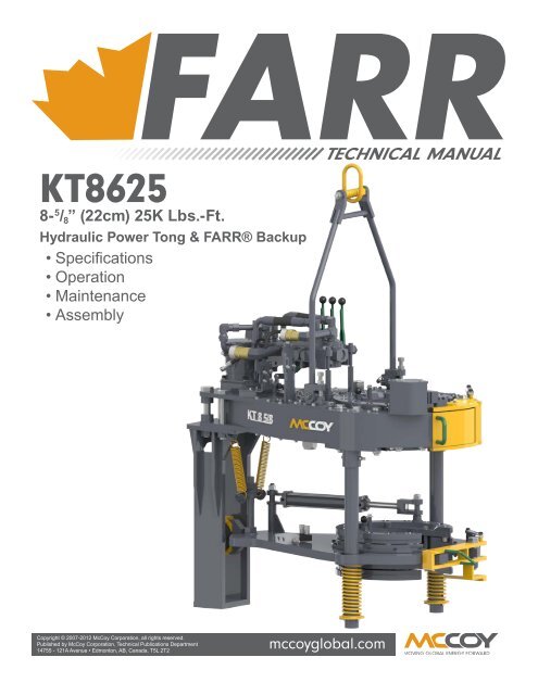
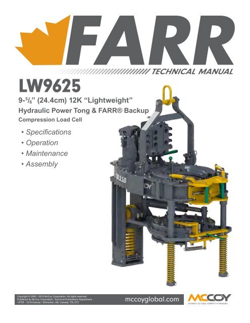
The large wrenches used for turning when making up or breaking out drill pipe, casing, tubing, or other pipe; variously called casing tongs, rotary tongs, and so forth according to the specific use. Power tongs are pneumatically or hydraulically operated tools that spin the pipe up and, in some instances, apply the final makeup torque.†

BOP stack: A series of blow out preventers stacked together using an equalizing and bleed of spool. Stack normally consists of an annular; equalize spool and a set of stripping rams. In snubbing operations the BOP stack is considered a secondary BOP. When working in conjunction with a workover, service or drilling rig the rig supplies the primary BOP’s.
Counter Balance Winches: A winch that can hydraulically counter balance the weight it is picking up. This gives the winch the ability to automatically feed off should the load placed upon it become greater than the actual weight being held via the hydraulics. Typically the snubbing unit will have two of these winches.
Equalize line: High pressure line pipe, chick sans (swivels) and valves for use during a snubbing operation to equalize or bleed off pressures within different chambers in a snubbing BOP stack.
Equalize spool: A ported spool for use in a snubbing operations allowing the operator the ability to equalize or bleed off certain sections of the BOP stack.
Gas well snubbing: Workover or completion work on a gas well which is either live or underbalanced with a rig assist or self-contained snubbing unit. Many gas well formations are fluid sensitive making a snubbing operation ideal for maximum production of the well. Eliminates the need for expensive kill fluids.
Guide Tube: Any arrangement of support system that prevents columnar buckling of the pipe being snubbed. Typical arrangements can be telescopic or static depending on the design of the snubbing unit structure.
Live well completions: A well condition where tubulars and tools are pulled or inserted into a well with the use of a rig assist snubbing unit or self-contained snubbing unit. The well has surface pressure from the down hole formations. Wells can be either gas or oil.
Live well workovers: Describes the condition of a gas or oil well is in when tubulars are snubbed in or out of well. There is pressure at surface in these wells making them ideal candidates for snubbing operations.
Lower snubbing basket: The work floor area which allows access to the snubbing crew to the BOP stack components and stationary snubbing and heavy slips.
Passive Rotary: A turn-table integrally mounted in the snubbing unit traveling plate which allows the rotation of the string with the slips closed on the pipe in either the snub mode or pipe heavy mode. This rotary must be driven with an external force be it by hand or with a power swivel rigged above the unit.
Pipe Heavy: In regards to snubbing, this is a pipe condition in which the tubing has sufficient string weight to overcome the forces acting on its cross-sectional area. Once the weight is sufficient, it overcomes the force applied by the pressure in the well and will fall under its own weight into the well.
Pipe Light: In regards to snubbing, this term describes the condition when the well bore forces acting on the cross-sectional area of the pipe being snubbed are greater than string weight; if tubing is not controlled, the snubbing unit will eject itself from the well.
Power-Pack: This is the prime mover that provides the force needed to turn hydraulic pumps which allow the operation of the snubbing jack and BOP systems. Diesel engines are the most common form, although electric drives are also utilized in special circumstances.
Powered Rotary: A turn-table integrally mounted in the snubbing unit traveling plate which allows the rotation of the string with the slips closed on the pipe in either the snub mode or pipe heavy mode. This rotary is driven with hydraulic motors, allowing the unit to perform string rotation without external support equipment.
Rig assist snubbing: A mobile snubbing unit, either truck-mounted or skid-mounted, that works in conjunction with a workover, service or drilling rig for workover or completions work on a live well or underbalanced well. Unit is capable of running or pulling tubulars and tools under pressure.
Scalloped spool: A spacer spool modified for snubbing to allow well bore pressures to equalize or bleed off around the tubing hanger when landing or pulling the hanger.
Self contained snubbing:A snubbing unit which stands alone by itself with no need of a service, workover or drilling rig. A self-contained unit is capable of workover or completion work on a live well or underbalanced well or indirect.
Snubbing: A procedure in which tubing is run or pulled from a well, which is in an underbalanced or live well condition. Snubbing units have specialized pressure control devices which permit them to deliver drilling, completion and workover services while there is pressure in the wellbore. Snubbing units eliminate the need to neutralize well pressure prior to servicing and therefore avoid the formation damage which neutralizing pressure can have on a well’s ability to produce.
Snubbing Assistant: This person’s position is primarily focused on taking direction from the snubbing operator, and entails routine maintenance, pipe handling and power tong operation.
Snubbing jack: The structure of the unit designed to withstand engineered ratings for both the pipe weight and the force applied by the unit’s hydraulic cylinders. The hydraulically operated equipment which enables crews to work on underbalanced or live well.
Snubbing Operator:Equivalent to a driller position, the snubbing operator physically operates the snubbing unit and takes direction from the snubbing supervisor. The operator is responsible for managing the daily activities of the rest of the snubbing crew, and ensuring that the equipment is functioning as designed.
Snubbing slips: A set of hydraulically actuated slips which can be run either inverted or right side up to control the movements of pipe in conjunction with a snubbing jack to insert or extract tubulars under live well or underbalanced conditions.
Snubbing Supervisor:Equivalent to a rig manager or tool push, the snubbing supervisor is responsible for all aspects of the snubbing unit and its operations. He/she is the direct liaison to the oil company representative he/she is working for. All members of the snubbing crew are subordinate to the snubbing supervisor. Typically the supervisor will have in excess of 10 years’ experience in snubbing operations.
Snubbing unit: A hydraulically actuated unit with slips, BOP stack and hydraulic jack for inserting or pulling tubing and BHA’s from underbalanced or live well conditions.
Stand alone snubbing (see self contained unit): Use of a snubbing unit by itself without the aid of a service, workover or drilling rig. Unit is capable of workover or completion work on a live well or underbalanced well.
Stationary snubbing slips: A set of snubbing slips that are typically mounted on top of a BOP stack which will hold pipe that is in a pipe light or neutral state.
Stripping: : During snubbing operations this is the procedure where you move pipe through a closed preventer (pipe rams or annular) on a live or underbalanced well containing pressure from the well bore with a closed preventer.
Stripping on: : The procedure in which a snubbing unit is rigged onto a service, workover or drilling rig, which is holding the pipe heavy tubing string with their tubing slips and not with a tubing hanger landed.
Stripping Ram: A hydraulically operated ram style BOP used during snubbing and stripping operations. Typically the ram front insert is a sacrificial material that is easily replaced for extended stripping. Materials for the inserts can be custom ordered for the application at hand.
TEP: A type of tubing plug developed for snubbing to control well bore pressures inside the tubing. Only viable for snubbing in operations. The plug is a machined collar with a removable disc and “o” ring. Once the tubing string has been snubbed in, the disc can be knocked out by equalizing the tubing string and flowing the casing. Once an overbalanced condition has been achieved inside the tubing string, the disc will fall out. Disc may also be removed by sand line or wire line tapping down on the disc once tubing string has been equalized with casing pressures.
Traveling plate: The plate which connects the rods from the hydraulic cylinders together on a snubbing unit where the traveling and heavy slips are attached. There are many cylinder configurations and stroke lengths possible depending on job requirements.
Traveling snubbing slips: A set of slips mounted upside down on a snubbing jacks traveling plate, which controls the movement of tubing in or out of a well. Slips will hold tubing only when tubing is in the pipe light state.
Underbalanced:A term to describe the pressure conditions in a well. Formation pressure is greater than the hydrostatic pressure of fluid, mud, etc… exerted on the formation causing pressure to migrate to surface in a well. A well in an underbalanced state is a prime candidate for snubbing.
Underbalanced completions: The condition of a well when completion services such as snubbing are performed. Formation pressure is greater than the hydrostatic pressure inside the well bore causing pressure to be at surface in the well. Underbalanced completions are prime candidates for snubbing. Typically wells have been perforated before snubbing unit arrives and the unit snubs in a production string to allow the well to be produced.
Underbalanced drilling: This term describes the condition of the well when drilling operations are ongoing. Snubbing units are used to snub out drill strings, i.e. bit changes and then snub in the drill string again or run productions strings.
Underbalanced workovers: The well is live with pressure to surface when workover operations are performed. Rig assist snubbing or self-contained snubbing units are used for the running or pulling of tubulars and BHA’s. Typically the snubbing unit pulls pipe from the well, the original zone is worked over, abandoned, or a new zone perforated and the snubbing unit snubs the production string back into the well.
Well control:In regards to snubbing, well control is the operation of containing well bore pressure with the use of a blowout preventer stack and tubing pressure by the use of a plugging system.
API Spec 7 2010 also includes a comprehensive listing of best practice guidelines for just about any drilling and well servicing equipment operations you can think of.


 8613371530291