
power tong test stand in stock
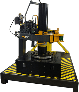
Texas International Oilfield Tools (TIOT) offers a free standing test stand for testing of hydraulic casing and tubing power tongs. The test stand is designed to resist torque applied by a power tong through a test mandrel.
The test stand is an air operated device that utilizes a hydraulic active dual spring disc brake chamber in order to apply friction force (“brake” action) to the rotating (or stationary) test mandrel mechanism. The power tong is tested by applying torque to the test stand’s mandrel. The test stand’s brake is activated by pushing and twisting clockwise the red control box button on the control box. A brake foot pedal is supplied as backup for the mini power unit. Using the control box mounted on the test stand, the black knob regulates pressure.
Before your tongs see any action, it’s essential to perform a tong test. Our tong testing stand allows you to test both hydraulic casing and tubing power tongs. Tong testing works by resisting the torque applied by the power tongs through a test mandrel. The tong test stand can be used for tool testing, certifying torque requirements, as well as training personnel on new, or unfamiliar equipment.
Tongs - Power - BJ sucker rod tong adopts advanced sucker rod or tubing technology and has a compact structure, high reliability and is safe and convenient to operate.
Tongs - Power - New Carter Tool Co. Inc., CT93R Hydraulic powered tubing tong. Complete with 2-3/8" to 3-1/2" jaw assemblies, standard motor, torque gauge assembly, pressure relief valve... More Info
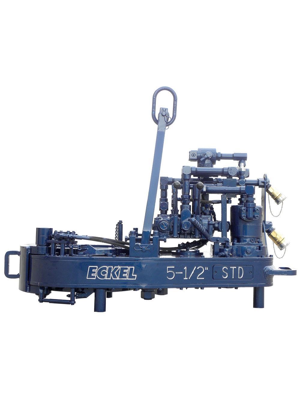
Tongs - Power - New Carter Tool Co., Inc. 5-1/2" CTSX Hydraulic Tubing Tong with heavy case and cover; complete with rigid hanger assy., suspension spring assy., front end control assy.,... More Info
Tongs - Power - New Carter Tool Co. Inc. M-Series power sucker rod tongs, complete with spring hanger assy., gate assy., front end control assy., pressure gauge assy., two 90 degree XH s... More Info
Tongs - Power - New Carter Tool Co., Inc. 4-1/2" RSX Hydraulic Tubing Tong with heavy case and cover; complete with rigid hanger assy., suspension spring assy., front end control assy., ... More Info
Tongs - Power - D D 58-93-2-R Power Tubing Tong is smaller, lighter, and faster than the Foster 5893R. The D D 58-93-2-R Tong is capable of gripping tubulars from 1 5/16" to 7" o.d. More Info
Tongs - Power - FARR TONG MODEL KT 14,000 RINEER GA37 MOTOR, LIFT VALVE ASSEMBLY TORQUE CAPACITY: 50,000 FT/LB SIZE RANGE 4 1.2-14 WITH SAFETY DOOR MOST SIZES OF FARR POWER TONGS ARE IN ... More Info
Tongs - Power - FARR TONG MODEL KT20,000 STAFFA 080 MOTOR, LIFT VALVE ASSEMBLY TORQUE CAPACITY: 50,000 FT/LB SIZE RANGE: 7-20 MOST SIZES OF FARR POWER TONGS ARE IN HOUSTON, IN STOCK READ... More Info
Tongs - Power - FARR MODEL KT5500 HYDRAULIC TUBING TONG C/W 2 SPEED RINEER MOTOR, SIZE RANGE: 2-3/8 IN. - 5-1/2 IN. OD, TORQUE RTED: 18,700 FT/LB C/W SAFETY DOOR MOST SIZES OF FARR POWER... More Info
Tongs - Power - FARR TONG MODEL KT5500 TORQUE CAPACITY: 18000 FT/LB SIZE RANGE: 2 1/16-5 1/2 OD WITH SAFETY DOOR MOST SIZES OF FARR POWER TONGS ARE IN HOUSTON, IN STOCK READY FOR IMMEDIA... More Info
Tongs - Power - FARR TONG MODEL KT5500 5 1/2 IN. TONG TORQUE CAPACITY: 18,000 FT/LB SIZE RANGE: 2 1/16-5 1/2 IN. OD, RINEER 15-13 MOTOR, HIGH TORQUE CLINCHER BACKUP TRIPLE VALVE ASSEMBLY... More Info
Tongs - Power - FARR TONG MODEL KT7585 TORQUE CAPACITY: 25000 FT/LB SIZE RANGE: 2 1/16-8 5/8 OD WITH SAFETY DOOR MOST SIZES OF FARR POWER TONGS ARE IN HOUSTON, IN STOCK READY FOR IMMEDIA... More Info
Tongs - Power - FARR TONG MODEL KT7585 8 5/8 IN. TONG TORQUE CAPACITY 25,000 FT/LB SIZE RANGE: 2 1/16-8 5/8 IN. OD, RINEER 15-15 MOTOR CLINCHER BACKUP, TRIPLE VALVE MOST SIZES OF FARR PO... More Info
Tongs - Power - FARR TONG MODEL LW9625 TORQUE CAPACITY 12000 FT/LB SIZE RANGE 2 7/8 -9 5/8 OD WITH SAFETY DOOR MOST SIZES OF FARR POWER TONGS ARE IN HOUSTON, IN STOCK READY FOR IMMEDIATE... More Info
Tongs - Power - Farrs newest tubular connection tool offers a significantly reduced rig footprint, while continuing to deliver power & uncompromising reliability. The simple design drast... More Info
Tongs - Power - Farr Canada"s newest tubular connection tool offers a significantly reduced rig footprint, while continuing to deliver power and uncompromising reliability. The simple de... More Info

The 14-100 hydraulic power tong provides 100,000 ft-lb (135,600 N∙m) of torque capacity for running and pulling 7- to 14-in. casing. The tong has a unique gated rotary, a free-floating backup, and a hydraulic door interlock.
Our 14-50 high-torque casing tong provides 50,000 ft-lb (67,790 N∙m) of torque capacity for running and pulling 6 5/8- to 14-in. casing. The tong has a unique gated rotary, a free floating backup, and a hydraulic door interlock.
The 16-25 hydraulic casing tong provides 25,000 ft-lb (33,900 N∙m) of torque capacity for running and pulling 6 5/8- to 16-in. casing. The tong features a unique gated rotary and as many as seven contact points that create a positive grip without damaging the casing.
Rigged up without rig modifications, our 21-300 riser tong is the only tong capable of producing 300,000 ft-lb (406,746 N∙m) of continuous rotational torque in both makeup and breakout mode. The power it achieves in a compact size compares with a conventional 24-in. casing tong.
The 24-50 high-torque casing tong provides 50,000 ft-lb (67,790 N∙m) of torque capacity for running and pulling 10 3/4- to 24-in. casing. The tong features a unique gated rotary, a free-floating backup, and a hydraulic door interlock.
The 30-100 high-torque casing tong provides 100,000 ft-lb (135,600 N∙m) of torque capacity for running and pulling 16- to 30-in. casing. The tong features a unique gated rotary, a free-floating backup, and a hydraulic door interlock.
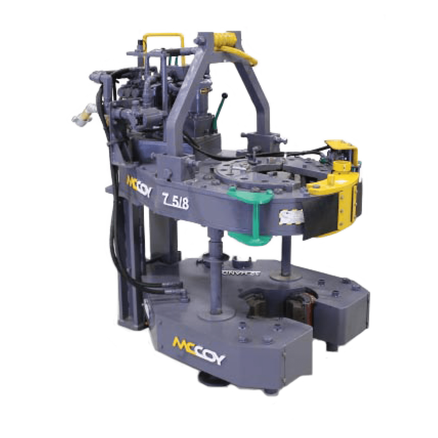
The 5.5-15 hydraulic tubing tong provides 15,000 ft-lb (20,340 N∙m) of torque capability for makeup and breakout of 1.66- to 5.5-in. tubing and premium or standard connections on corrosion‑resistant alloy tubulars. The tong features an ergonomic, lightweight design with a free-floating hydraulic backup.
The 7.6-30 hydraulic tubing tong provides 30,000 ft-lb (40,670 N∙m) of torque capability for makeup and breakout of 2 3/8- to 7 5/8-in. tubing and premium or standard connections on corrosion‑resistant alloy tubulars. The tong features an ergonomic, lightweight design with a free-floating hydraulic backup.
Our SpeedTork 8.0-70 tong provides torques up to 70,000 ft-lb (94,900 N∙m) and 360° rotation in makeup and breakout operations. It can torque drillpipe connections, drillstring components, drilling tools, packers, couplings, and valves.
K&S Power Tongs committs to providing quality casing services in a safe, reliable, cost efficient and timely manner. Safety is everyone’s full time job and we are committed to the prevention and elimination of all safety nad health hazards. All operators are specially trained and industry safety certified. Safety is never compromised. Unsafe acts are never tolerated and our employees are held accountable to work safe.
K&S Power Tongs offers coventional and integral power tong services, volant casing running tools, computer torque-turn systems, power thread washing, thread inspection, handling equipment rentals and light oilfield hauling.
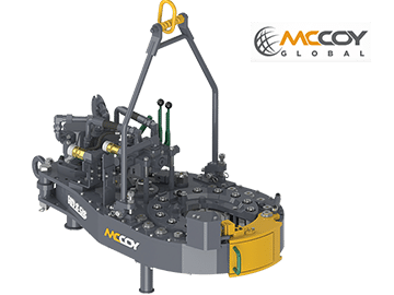
Casing tong handling tools (CTHTs) improve safety and efficiency by reducing the time to complete casing running operations. The CTHT automatically moves the casing tongs to and from well center, which decreases the personnel required to make up casing on the rig floor. Additionally, the CTHT increases the speed of running the casing tong to and from well center. Operations are faster and more consistent, from shift to shift, crew to crew.
The CTHT is an upgrade to an existing offshore drilling rig. This tool lifts and handles casing tongs, ranging in size from 7 5/8 in to 30 in, to and from the well center during casing running operations. And it can be used on any Cameron SmartRacker vertical pipe handling system or any other brand of column racker.
- DIES FOR PIPE AND TUBING TONGS Filed April 18. 1960 4 Sheets-Sheet 1 CROSS CUT DEPTH TOOTH DEPTH i n N a 3 Q 4 L- I 2 M 4 it m E 8 I o PEI-I 21 m m; E 1 Q :0;
u.| l 5* I 5 i" l M 4 l 4 INVENTORS 0.5. MARQUIS 8 J.H. PROVINCE N n v: -n o l o m 2 I I J BY z ,w% r I 7 ATTORNEYS March 1964 D. E. MARQUIS ETAL 3 3 DIES FOR PIPE AND TUBING TONGS Filed April 18. 1960 4 Sheets-Sheet 2 x (PENETRATION CROSS SECTION) INVENTORS D. E. MARQUIS J.H. PROVINCE A 7" TORNEKY March 10, 1964 D. E. MARQUIS E" I"AL 3,
DIES FOR PIPE AND TUBING TONGS 4 Sheets-Sheet 4 Filed April 18. 1960 INVENTORS D.E. MARQUIS J.H. PROVINCE A T TORNEVS United States Patent 3,124,023 DIES FOR PIPE AND TUBING TONGS Duane E. Marquis and John H. Province, Bartlesville,
0kla., assignors to Phillips Petroleum Company, a corporation of Deiaware Filed Apr. 18, 1960, Ser. No. 22,842 19 tllaims. (Cl. 81186) This invention relates to a die for pipe and tubing tongs. In one aspect this invention relates to an improved die which, when employed in pipe and tubing tongs, causes less damage to the pipe or tubing being made up or broken out with the aid of said tongs. In another aspect this invention relates to an improved die for pipe and tubing tongs which die provides maximum contacting surface of essentially the same curvature as the outer circumference of the pipe or tubing to which said die is applied.
Thus, it has been found that much of the handling damage is caused by the dies in the tongs employed in making up and breaking out joints of tubing. As a result of extensive field, laboratory, and experimental tests we have invented a new die for pipe and tubing tongs, which die reduces damage to said pipe or tubing to the minimum, but yet provides efiicient safe handling in making up and breaking out strings of pipe or tubing.
An object of this invention is to provide an improved die for pipe and tubing tongs. Another object of this invention is to provide an improved die for pipe and tubing tongs which provides maximum tooth contacting areas and minimum tooth penetration, thereby resulting in the elimination or mitigation of tong die damage. Another object of this invention is to provide an improved die which is less subject to clogging. Still another object of this invention is to provide an improved die which is easier to clean. Another object is to provide an improved power tong adapted to be employed with said die. Other aspects, objects and advantages of the invention will be apparent to those skilled in the art in view of this disclosure.
Thus, according to the invention there is provided a die for pipe and tubing tongs, said die comprising: a bar-like body having a concave working face provided with a plurality of buttressed teeth thereon; said teeth having a substantially triangular cross section and being arranged in from 5 to 9 spaced apart parallel rows per inch of said concave working face; each of said teeth having an apex length or contacting surface within the range of to 4 inch; said teeth being spaced apart in said rows a distance within the range of from A to inch; and said apexes of said teeth providing an arcuate contacting surface having a curvature essentially the same as the outer circum ference of the pipe or tubing with which said die is to be employed.
Each of said elements is critical to the combination, within the above specified limits, in that each cooperates with the others to provide a unitary end result, i.e., a die, which when employed in a pipe or tubing tong and applied to a pipe or tubing, will cause minimum damage to said pipe or tubing.
FIGURE 4 is a diagrammatic view, partly in cross section, illustrating a conventional tubing power tong which has been modified to employ the dies of the invention.
FIGURE 5 is an enlargement of the gripping mechanism of the power tongs of FIGURE 4 and illustrates the relationship between the teeth of the die of the invention and the circumference of a pipe or tubing.
In the specific embodiment illustrated the back face 24 of the die is slightly convex and the side faces 26 are tapered. The amount of curvature on said convex back is not critical so long as it is not large enough to cause instability. In the die illustrated said curvature is about equal to the curvature of a circle having a radius of 12 inches. If desired, said back face 24 can be fiat. Said tapered sides are tapered at an angle of about 15 degrees. Said tapered sides are advantageous in holding the dies of the invention in the grooves provided in the bushing and jaw of the tongs. Said convex back is provided to enable or provide a slight rocking motion within said grooves when the dies are first brought into contact with the pipe or tubing and thus aid in fitting or placing the die to the tubing or pipe with which it is to be employed. Opening 25 is provided for convenience in stringing the dies for temporary storage as when a string or wire is passed through a set of dies to keep them separate from other similar dies. The specific embodiment of the die of the invention illustrated in FIGURES 1, 2 and 3 has an overall length of 3 /8 inches and a width at the base of 2 inches.
Referring now to FIGURE 4, there is illustrated a conventional power tong which has been modified to accommodate the dies of the invention. Said power tong is of the general type illustrated in US. Patent 2,618,467 issued to C. A. Lundeen on November 8, 1952. Said power tong comprises a bushing 27 and a jaw 28 which are part of an inner ring assembly 29 which is actuated by an outer ring assembly 31. Said bushing 27 is provided with two adjacent tapered grooves 34 and 36 which contain dies A and B fabricated in accordance with the invention. Said dies are held in place in said bushing and said jaw by means of cotter pins 35 at the top and bottom (not shown). The sides of said tapered grooves 34 and 36 are tapered at approximately the same angle as the side faces of said dies A and B but said grooves are slightly wider than said dies A and B so as to provide room for said dies A and B to rock on their convex back faces in said grooves when said jaw 28, containing die J, is brought into contact with a tubing (not shown). Said bushing 27 is stationary in said inner ring assembly 29 while said jaw 28 is hinged at the point 32 so that as said outer ring assembly 31 rotates in the direction indicated by the arrow with respect to said inner ring assembly, the roller 33 will roll along the cam surface of said jaw 28 and cause die I to be moved into contact with a tubing or pipe (not shown). Power tongs of the general type here illustrated are well known to those skilled in the art and no further explanation of their operation is believed necessary. Further details concerning the operation of power tongs of this general type can be found in said Patent 2,618,468.
FIGURE 5 illustrates more clearly the relationship between the dies A, B, and I, fabricated in accordance with the invention, and a tubing which has been placed in the power tongs and jaw 28 closed. It will be noted that the contacting surface provided by the teeth of each of said dies A, B and J covers an area of the tubing equivalent to about 70 degrees of the circumference of said tubing, or a total area of 210 degrees for three of said dies. In the practice of the invention it is preferred that each die cover an area of the tubing which it contacts equivalent to at least about 60 degrees of the circumference of said tubing. This feature of the invention, i.e., the apexes of the teeth of said dies providing an arcuate contacting surface having a curvature essentially the same as the outer circumference of the pipe or tubing with which said dies are employed, provides an important advantage of the invention.
Referring to said Patent 2,618,468 it will be noted that each of the dies 93, 94, and 95 has a maximum contact surface of only about 20 degrees on the surface of the pipe or tubing. Said dies 93, 94 and 05 in FIGURES 5 and 6 of said Patent 2,618,468 are conventional flat face dies provided with four teeth running the entire length of the die. Due to the flat faces of said standard die and the curvature of the tubing, only one of said teeth and perhaps a trace of a second tooth makes contact with the tubing. Since each die is approximately 3% inches long, this results in a total of only about 17 lineal inches of contact, all concentrated in three or more continuous die marks. This concentration of the die marks is highly undesirable, particularly with the new type tubings, due to the stress patterns developed.
We have found, in general, that dies having a total penetration cross section within the range of 0.12 to 0.19 square inches and a tooth length within the range of A to 4 inch, are satisfactory. Using said penetration cross section as a guide, a great number of tests, both in the laboratory and in the field, were run using both conventional standard product dies available from various die manufacturers and special dies made according to special specifications. These test dies included various tooth styles, patterns, and sizes, such as symmetrical, buttress and circular styles, pyramid, coarse and standard long tooth, fiat and curved contacting surfaces, and flat and curved back surfaces. Dies having a flat working face were eliminated early in favor of dies having a concave working face. While it appeared that a buttress type tooth was preferred so as to obtain better initial bite and minimum slip, it was found that with all other factors being substantially the same, said buttress type teeth caused more penetration than could be tolerated. However, it was unexpectedly found that when the individual tooth contacting area was increased, the penetration of the buttress type tooth was decreased without sacrificing any appreciable amount of its superior bite and minimum slip properties.
EXAMPLE I A large number of dies having various tooth types and arrangements were tried in the field under actual operating conditions on tubing installed in operating wells. The objective of these tests was to determine the type of die which caused the minimum amount of die damage; and to determine ways and means for holding tooth penetration to a maximum of 10 mils (0.010 inch), preferably 6 mils if possible, when employing up to 6000" ft.-lbs. maximum applied torque.
The candidate dies were installed in a conventional power tong similar to that illustrated in FIGURE 4 herein and that illustrated in said Patent 2,618,468. The bushing and jaw of said power tongs were modified where necessary to accommodate the candidate dies.
From these tests all dies having a straight working face and all dies having tooth types other than (1) buttress type and (2) symmetrical type, were eliminated. The test results given in Table I below on five different dies are representative of the tests on dies having said two types of teeth.
The data given in the above Table I show that the total penetration cross section (X for dies 1, 3, and 5 having symmetrical type teeth were much less than for dies 2 and 4 having buttress type teeth. These data show that a die having symmetrical type teeth develops less penetration cross section for the same applied torque than does a die having buttress type teeth. Thus, from the standpoint of penetration cross section, a die having symmetrical type teeth would be preferred.
The test data also showed that when considered from the standpoint of penetration alone, the dies having symmetrical type teeth would be preferred to dies having buttress type teeth because of the smaller penetration.
Thus, the data showed that when employing dies having buttress type teeth, all three dies A, B and I do about the same amount of work. From this standpoint the dies having buttress type teeth are preferred.
EXAMPLE II On the basis of observations during the tests described in the above Example I three dies having symmetrical type teeth and meeting the above determined total penetration cross section requirement of 0.0886 sq. in. for dies having symmetrical type teeth were fabricated. It was desired to reduce the average tooth penetration to 3 mils (0.003 inch) if possible. In order to fit into the power tongs being employed the overall dimensions of each die were set at a length of 3% inches and a width of 2 inches. A tooth contact length of inch with inch space between the teeth in the row was chosen. For a die 3% inches in length this will permit 30 teeth per row or a total contact area of 0.936 inches per row of teeth.
Said dies were then heat treated to impart a Rockwell C hardness of 61-63 to the teeth surfaces. When tested in a power tong on 2.875 inch O.D. tubings made of 4340 steel and tubings made of 9 chrome steel having Rockwell C hardnesses in the range of 25 to 32, and employing from 2500 to 5000 ft. lbs. of applied torque, the dies slipped and the die teeth acted much in the manner of a cutting tool.
EXAMPLE III On the basis of observations during the tests described in the above Example I three dies having buttressed type teeth and meeting the above determined total penetration cross section requirement of 0.1595 sq. in. for dies having buttress type teeth were fabricated. The average tooth penetration was set at 3 mils (0.003 inch), die length at 3% inches, and die width at 2 inches for the same reasons as in Example II. A tooth contact length of inch with 4 inch space between the teeth in the row was chosen. For a die 3% inches in length this will permit 17 teeth per row or a total Contact area of 0.1591 inches per row.
Said dies were then heat treated to impart a Rock well C. hardness of 60-61 to the teeth surfaces. When tested in a power tong on 2.375 inch O.D. tubings made of 4340 steel and tubings made of 9 chrome steel having Rockwell C hardnesses ranging from 25 to 32, and employing from 2500 to 5000 ft. lbs. of applied torque, the action of the dies was satisfactory in every respect.
The die described immediately above is the die illustrated in FIGURES 1, 2 and 3. In numerous subsequent tests of this die on various types of tubings and employing from 2000 to 3000 ft. lbs. of applied torque on makeup, the tooth penetration has averaged from 2 to 4 mils; when employing from 2000 to 5000 ft. lbs. of applied torque on break-out, the tooth penetration has averaged from 4 to 6 mils. Considering the severity of use, the die life has been entirely acceptable.
As will be realized by those skilled in the art in view of this disclosure, variations in the outside diameter of the pipe or tubing with which the dies of the invention are employed will affect the performance of said dies. However, due to the general high standard of products produced by American manufacturers of pipe and tubing, said variations are, in general, very small. For example, the API specifications for such products provide that tubings having an outside diameter of 4" and smaller, tolerance permitted in said outside diameter is plus or minus 0.031 inch. Tubing manufactured by American manufacturers is nearly always well within this tolerance. It will also be realized by those skilled in the art that variations in the hardness, e.g., Rockwell C, of the pipe or tubing will also affect the performance of said dies. It is believed clear that the teeth faces of said dies should have a hardness greater than the hardness of the pipe or tubing with which said dies are to be employed.
1. A die for pipe and tubing tongs, said die compris ing: a bar-like body having a concave working face provided with a plurality of buttressed teeth thereon; said teeth having a substantially triangular cross section and being arranged in from 5 to 9 spaced apart parallel rows per inch of said concave working face; each of said teeth having an apex length within the range of from to inch; said teeth being spaced apart in said rows a distance within the range of from to 4 inch; and said apexes of said teeth providing an arcuate contacting surface having a curvature essentially the same as the outer circumference of the pipe or tubing with which said die is to be employed.
2. A die for pipe and tubing tongs, said die comprising: a bar-like body having a concave working face provided with a plurality of buttressed teeth thereon; said teeth being arranged in from 5 to 9 spaced apart parallel rows per inch of said concave working face; each of said teeth having an apex angle within the range of 45 to degrees, an apex length within the range of to inch, a longitudinal depth Within the range of 0.01 to 0.1 inch, and a cross cut depth within the range of 0.03 to 0.07 inch, with one of said dimensions for said longitudinal depth and said cross-cut depth being less than the other said demension; said teeth being spaced apart in said rows a distance within the range of to A1. inch; and said apexes of said teeth providing an arcuate contacting surface having a curvature essentially the same as the outer circumference of the pipe or tubing with which said die is to be employed.
5. A die for pipe and tubing tongs, said die comprising: a bar-like body having a concave working face provided with a plurality of buttressed teeth thereon; said teeth being arranged in from 8 to 12 parallel rows spaced from 0.12 to 0.18 inch apart; each tooth having an apex length within the range of from to inch; said teeth being spaced apart in said rows a distance within the range of from to 4 inch to provide from 12 to 20 inches total lineal contacting surface and said apexes of said teeth providing an arcuate contacting surface having a curvature essentially the same as the outer circumference of the pipe or tubing with which said die is to be employed.


 8613371530291