
us power tong free sample

This invention is directed to apparatus and methods for aligning wellbore tubulars; and to power tongs used in making and breaking joints of tubular members such as wellbore casing and tubing; to parts thereof; including, but not limited to gripping elements, and methods of their use.
During the drilling of oil and gas wells and the production of materials therefrom, various operations require the connection and disconnection of successive lengths of threaded tubulars such as pipe, casing, or tubing. Tools known as tongs are used to "make" and "break" such connections. Certain known power tongs have a body, a rotary rotatably mounted in said body and at least one active jaw which, on rotation of the rotary is cammed against a pipe in the rotary and grips it for rotation with the rotary. In known arrangements the camming action is generated by a cam member which is bolted to the rotary and is shaped so that the active jaw is cammed against the pipe on rotation of the rotary relative to the active jaw in one sense and will be released on rotation of the rotary relative to the active jaw in the opposite sense.
With known tongs high torques are applied to tubulars due to combinations of factors such as thread sealing requirements, the presence of corrosion, the existence of distortion, and pipe size and weight. Both in the "make" direction of rotation when a shoulder is suddenly encountered, and in the "break" direction at initial engagement of the tong and disengagement of the threads high shock forces may arise; e.g., with a power-driven tong, in excess of 50,000 foot-pounds of torque may be exerted, while relatively small die elements on jaws of the tong engage the pipe with extremely high force loadings. Slippage occurs and pipe surfaces become marred, marked, indented, or otherwise damaged.
Dies for gripping jaws have been provided with multiple serrations, or penetration features, to provide the interference contact at the joint surface. Grip element penetration into the joint surface is limited and controlled. The distribution and balance of grip element energizing forces are critical factors in the design, development and evaluation of such tong mechanisms. Linkages, levers, wedges, and cams are used to balance force components. Grip elements, or dies, are accurately disposed within carrier bodies, or jaws, which span a circumferential segment of the joint surface.
Uneven die loading can cause excessive indentation, marring or damage to a tubular surface. Drag or braking devices are used in certain tongs to effect proper biting of the dies relative to the pipe. The head or other member supporting the dies is frictionally restrained to insure that the dies do not simply rotate with the rotary as the rotary is driven.
Other tongs use an endless belt, chain or flexible material loop for gripping a tubular. Such tongs are disclosed in U.S. Pat. Nos. 3,799,010; 3,906,820; 3,892,140; 4,079,640; 4,099,479; and 4,212,212. There are a variety of problems associated with certain of these tongs:
Endless chain is changed to accommodate tubulars of different size or apparatus is provided to maintain tubulars on a centered position for torque monitoring.
Slippage (which can cause galling and other damage to tubulars) occurs if the gripping element (belt, chain, etc.) loading mechanism does not maintain an adequate pre-load force on the tubular.
Jaw/die tongs and the belt/chain tongs are used with relatively hard and rigid metal tubulars such as casing and tubing. If these tongs are used with thick tubulars or tubulars made from relatively "softer" metals or from premium metals such as high alloy steels or low carbon steels or tubulars made from non-metal materials such as fiber glass, they often literally chew up the tubular. The use of strap wrenches is inadequate since the torque applied with such wrenches cannot be precisely controlled.
Certain tubulars are treated with a rust or corrosion resistant material or coating. If the coating is indented, gouged, or broken, its protective purpose is defeated. Producing enough force in a tong to join such tubulars while not injuring a protective coating presents a dilemma.
The present invention, in certain embodiments, discloses a power tong for joining tubulars so that marking of, indentation of, and surface injury to tubulars are reduced or eliminated. In one aspect a power tong is provided and a method of its use for handling tubulars coated with a corrosion-resistant material which should not be broken or penetrated. In one embodiment such a tong has one or more gripping jaws with gripping elements made of aluminum alloys, zinc, zinc alloys, aluminum, brass, bronze, cermet, plastic, fiberglass, metal alloys, or a combination thereof which present a smooth face (straight or curved) to a tubular without any teeth, pointed projections, or toothed dies. In one aspect the gripping elements are releasably connected directly to jaws. In another aspect the gripping elements are releasably connected to a jacket or holder which itself is releasably connected to a jaw.
In certain aspects to achieve desired gripping forces, the gripping elements are relatively long longitudinally and the jaws are correspondingly enlarged or appropriate extension apparatus is connected thereto. With certain gripping elements the surface for contacting the tubular is flat; with other elements the surface is radiused to correspond to the curve of an outer tubular surface of a tubular to be rotated.
In order to effectively grip a tubular with gripping elements without teeth, points, or projections so that slippage is prevented, a larger normal force between the jaw and the tubular is needed to maintain gripping-element pipe contact. Pre-loading of jaws with one or more of these gripping elements is achieved, in certain embodiments of this invention, with a pre-load cylinder connected between a fixed gripping jaw and a movable gripping jaw. The cylinder applies a continuous pre-load force on the movable jaw which is not concentrated enough to injure the tubular but is large enough to develop sufficient friction to prevent slippage. In one aspect the force applied by the cylinder is controllable and is adjustable as desired. In one aspect two pre-load cylinders are used, each connected to a different fixed jaw and one at each end of a movable jaw, so that no cylinder movement is required to change modes, e.g. from make-up to breakout. In one aspect one cylinder is used which can be switched from one end of a movable jaw to the other to switch modes of operation.
In one aspect the cylinder(s) are powered by a small air-driven hydraulic pump with an hydraulic fluid reservoir mounted on a plate on the movable or fixed jaw. Air is supplied to activate a motor of the pump and the pump then provides hydraulic fluid to move a piston of the hydraulic cylinder(s). The motion of the cylinder moves the movable jaw on its roller to travel to a pre-load position on the cam. The cylinder applies pressure until the hydraulic pressure is released. A hydraulic fluid accumulator and a valve may be used to maintain hydraulic pressure at all times so that the cylinder(s) continuously maintain the desired load on the jaw until the air supply to the pump is removed.
In another aspect the cylinders are connected to a rotary of the tong or to any other member that rotates with the rotary rather than to a fixed jaw. Such a pre-load system may, according to this invention, be used with any tong including a tong that does use toothed dies.
In one embodiment the present invention discloses a gripping arrangement for a tong with a sheet of grit which is preferably bonded to a carrier plate. In another embodiment the gripping arrangement comprises a layer of flexible material having a smooth flat surface or a surface with ridges and valleys, for example in the fashion of the surface of a file. The flexible material, in one aspect, is metal, for example sheet aluminum, zinc, brass, bronze, zinc alloy, aluminum alloy, stainless steel, or steel having a thickness of about 1.5 mm. The layer of flexible material may be used in conjunction with a carrier plate or on its own. In a further embodiment the gripping arrangement may comprise a layer of perforate material one of both surfaces of which are preferably coated with grit to facilitate adhesion. The layer will typically be formed from metal having a thickness of about 1.5 mm. The layer may be used in conjunction with a carrier plate or used on its own. In yet another embodiment the gripping arrangement may comprise a layer of expanded mesh, e.g. metal mesh, which has been flattened. One or both surfaces of the expanded mesh may be coated with grit and the layer may be used in conjunction with a carrier plate or used on its own. The grit may comprise, for example, diamond dust, particles of silicon, zircon, tungsten carbide and mixtures thereof. The gripping arrangement may comprise end plates which are attached to the carrier plate. Preferably, the carrier plate is provided with side flanges for insertion into a jaw holder. The present invention also provides a jaw assembly fitted with a gripping arrangement in accordance with the present invention. Preferably, the jaw assembly includes a jaw holder having an arcuate recess which accommodates an arcuate pad of resilient elastomeric material which supports said gripping arrangement. Advantageously, at least one shim is provided which is disposed between said arcuate pad of resilient elastomeric material and said gripping arrangement. The shim will be flexible and generally from 0.5 mm to 1.0 mm thick and made from sheet metal. The present invention also provides a tong fitted with at least two such jaw.
In one embodiment the present invention discloses an apparatus for aligning tubulars and includes a guide on one of a power tong and a backup tong. In one embodiment the apparatus has a socket centralizer mounted on said one of said power tong and said backup tong. In one aspect, said one of said power tong and said backup tong is said power tong. In another embodiment, the apparatus includes a power tong and a backup tong, and the guide is mounted on the power tong and apparatus is provided to maintain the power tong and the backup tong in a certain juxtaposition during a stabbing operation. Preferably, said apparatus includes locating rods on one of the power tong and the backup tong and blocks shaped to receive at least the ends of the locating rods on the other of the power tong and the backup tong. Advantageously, the backup tong is provided with at least two prismatic jaw assemblies to locate the backup tong in fixed juxtaposition with respect to a tubular being gripped.
The present invention, in one aspect, provides a jaw unit for use in a tong, which jaw unit comprises a jaw holder and a jaw movable with respect to said jaw holder, characterized in that said jaw is slidably mounted on said jaw holder. Preferably, said jaw is slidable with respect to said jaw holder about an arcuate path. Advantageously, said jaw has a gripping surface which is substantially arcuate for gripping the surface of a tubular and the center of curvature of such arcuate path lies between the center of curvature of said grip ping surface and said arcuate path. The gripping surface may be a continuous surface or defined by several spaced apart gripping elements. Preferably, the center of curvature of said arcuate path lies between the center of curvature of said grip ping surface and said gripping surface. Advantageously, the center of curvature of said arcuate path is substantially midway between the center of curvature of said gripping surface and said gripping surface. Preferably, one of said jaw and said jaw holder is provided with an arcuate track which defines said arcuate path, and the other of said jaw and said jaw holder is slidably mounted in said arcuate track.
The present invention also provides a jaw assembly comprising two jaw units in accordance with the present invention. Preferably, said jaw units are mounted for pivotal movement about a common pivot shaft. Advantageously, said jaw assembly includes means which bias said jaw units apart. The present invention also provides a rotary fitted with a jaw unit in accordance with the present invention, a rotary fitted with a jaw assembly in accordance with the present invention, and a tong fitted with a rotary in accordance with the present invention.
One of the features of existing tongs is that their rotaries are difficult to furnish. Thus, routine maintenance usually involves dismantling the whole rotary, checking the parts and reassembling the whole. While this is a straightforward procedure in the clean conditions of a workshop it can be problematic when carried out in a muddy field, in sand or in snow. The present invention aims to help solve this problem and provides a rotary which comprises a top section, a bottom section, and a peripheral wall therebetween, characterized in that at least one of said top section and said bottom section is provided with an elongate slot which, when said rotary is in use, accommodates a pivot shaft on which a jaw assembly can be pivotally mounted.
Jaw holders and jaws for tongs are traditionally machined from a solid piece. This is a comparatively expensive procedure. The present invention proposes to make such parts from a stack of individually cut laminations.
Such methods and devices including a power tong with at least one jaw with at least one tubular gripping element having a smooth gripping surface (flat or curved) and, in one aspect, such an element which is flexible;
Such methods and devices including apparatus to apply a pre-load to a gripping element carrier or jaw so the gripping element will adequately grip the tubular without slipping on it or damaging it; and
Such methods and devices wherein a single pre-load apparatus is movable to provide a pre-load on multiple jaws or gripping elements; or each such jaw or gripping element has its own pre-load apparatus;
Certain embodiments of this invention are not limited to any particular individual feature disclosed here, but include combinations of them distinguished from the prior art in their structures and functions. Features of the invention have been broadly described so that the detailed descriptions that follow may be better understood, and in order that the contributions of this invention to the arts may be better appreciated. There are, of course, additional aspects of the invention described below and which may be included in the subject matter of the claims to this invention. Those skilled in the art who have the benefit of this invention, its teachings, and suggestions will appreciate that the conceptions of this disclosure may be used as a creative basis for designing other structures, methods and systems for carrying out and practicing the present invention. The claims of this invention are to be read to include any legally equivalent devices or methods which do not depart from the spirit and scope of the present invention.
The present invention recognizes and addresses the previously-mentioned problems and long-felt needs and provides a solution to those problems and a satisfactory meeting of those needs in its various possible embodiments and equivalents thereof. To one skilled in this art who has the benefits of this invention"s realizations, teachings, disclosures, and suggestions, other purposes and advantages will be appreciated from the following description of preferred embodiments, given for the purpose of disclosure, when taken in conjunction with the accompanying drawings. The detail in these descriptions is not intended to thwart this patent"s object to claim this invention no matter how others may later disguise it by variations in form or additions of further improvements.
A more particular description of embodiments of the invention briefly summarized above may be had by references to the embodiments which are shown in the drawings which form a part of this specification. These drawings illustrate certain preferred embodiments and are not to be used to improperly limit the scope of the invention which may have other equally effective or legally equivalent embodiments.
FIG. 2A is a perspective view of a tubular connection system according to the present invention. FIGS. 2B and 2C are perspective views of a casing tong of the system of FIG. 2A.
FIG. 5A shows schematically an initial position of elements of a tong system according to the present invention. FIG. 5B shows pre-loading on a pipe of the jaws of the system of FIG. 5A. FIG. 5C shows a tubular gripped with the system of FIG. 5A.
FIG. 14 is a front elevation of a first embodiment of a flexible gripping member in accordance with the present invention and which is used in the jaw assembly shown in FIGS. 10 to 13.
FIGS. 1A-1C show a typical prior art power tong that uses fixed jaws and a movable jaw to grip pipe for tubular disconnecting and connecting operations. An outer case houses a powered rotary to which the jaws are mounted. A cam surface of the rotary moves a movable (ACTIVE or MASTER) jaw into (and away from) gripping contact with a tubular, e.g. pipe. Each jaw has toothed gripping inserts to facilitate engagement with the surface of the tubular (see FIG. 1B). FIG. 1C shows the tong in an "OPEN" position in which the tubular is not gripped.
The tong shown in FIG. 1A is a Weatherford Model 14.5-50 High Torque Tong. The brochure "New ! Weatherford Model 14.5-50 High Torque Tong," (1991) and the manual entitled "Model 14.5-50 Hydraulic Power Tong Installation, Operation and Maintenance" (1993) are submitted herewith and incorporated herein fully by reference for all purposes. It is to be understood that the teachings of the present invention are applicable to any tong and any tong system that has one or more gripping elements or jaws and that the Model 14.5-50 tong is shown here for illustrative purposes and not by way of limitation of the scope of the present invention.
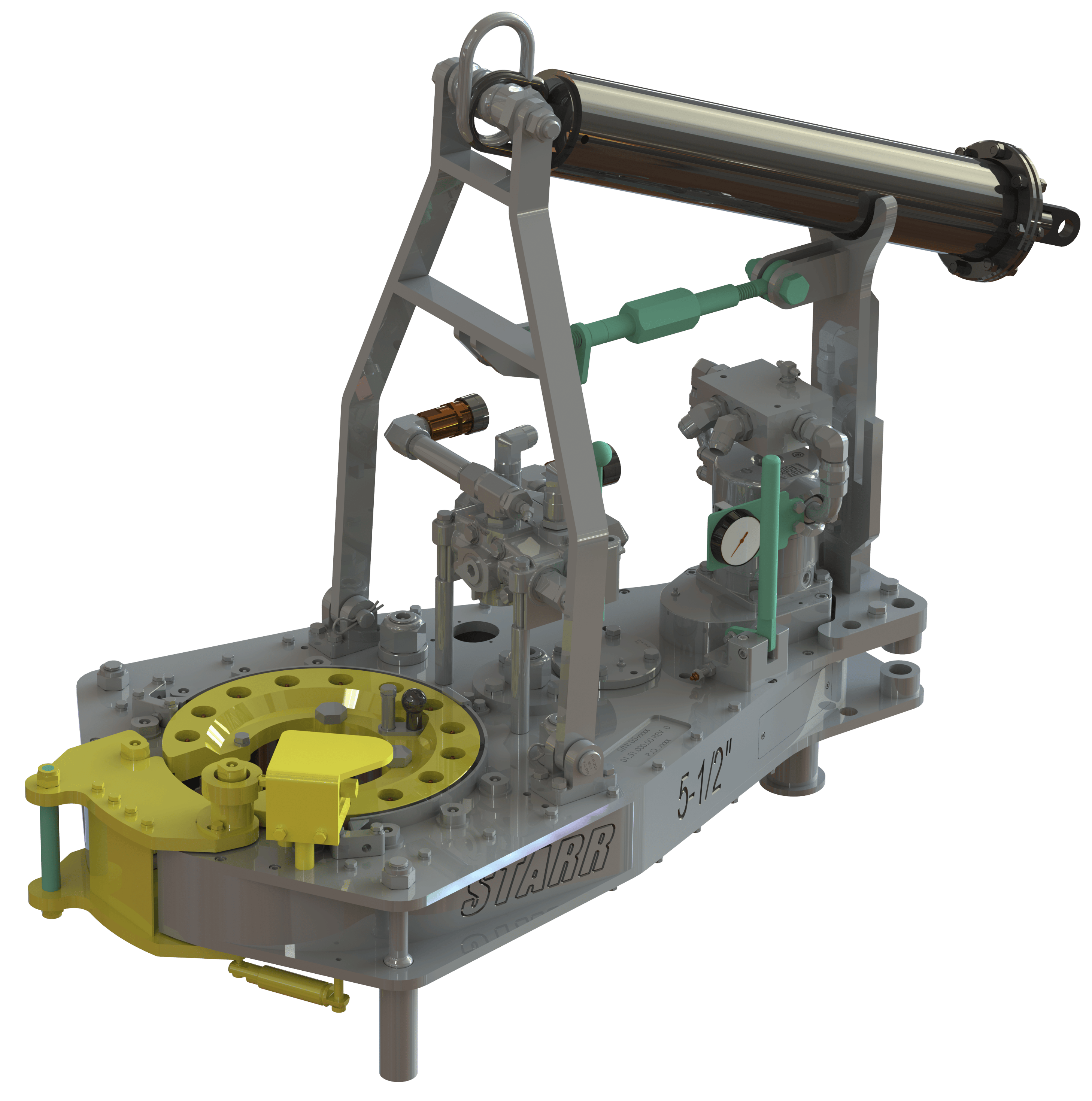
As shown in FIG. 2A a system 10 according to the present invention includes a power tong 100 according to the present invention which is like the tong of FIG. 1A but which also includes a unique jaw system 110 with inserts 150 on fixed jaws 120 and insert 152 on movable jaw 122 and at least one jaw pre-load assembly like that shown in FIG. 5A. The system 10 includes a free floating backup tong 12.
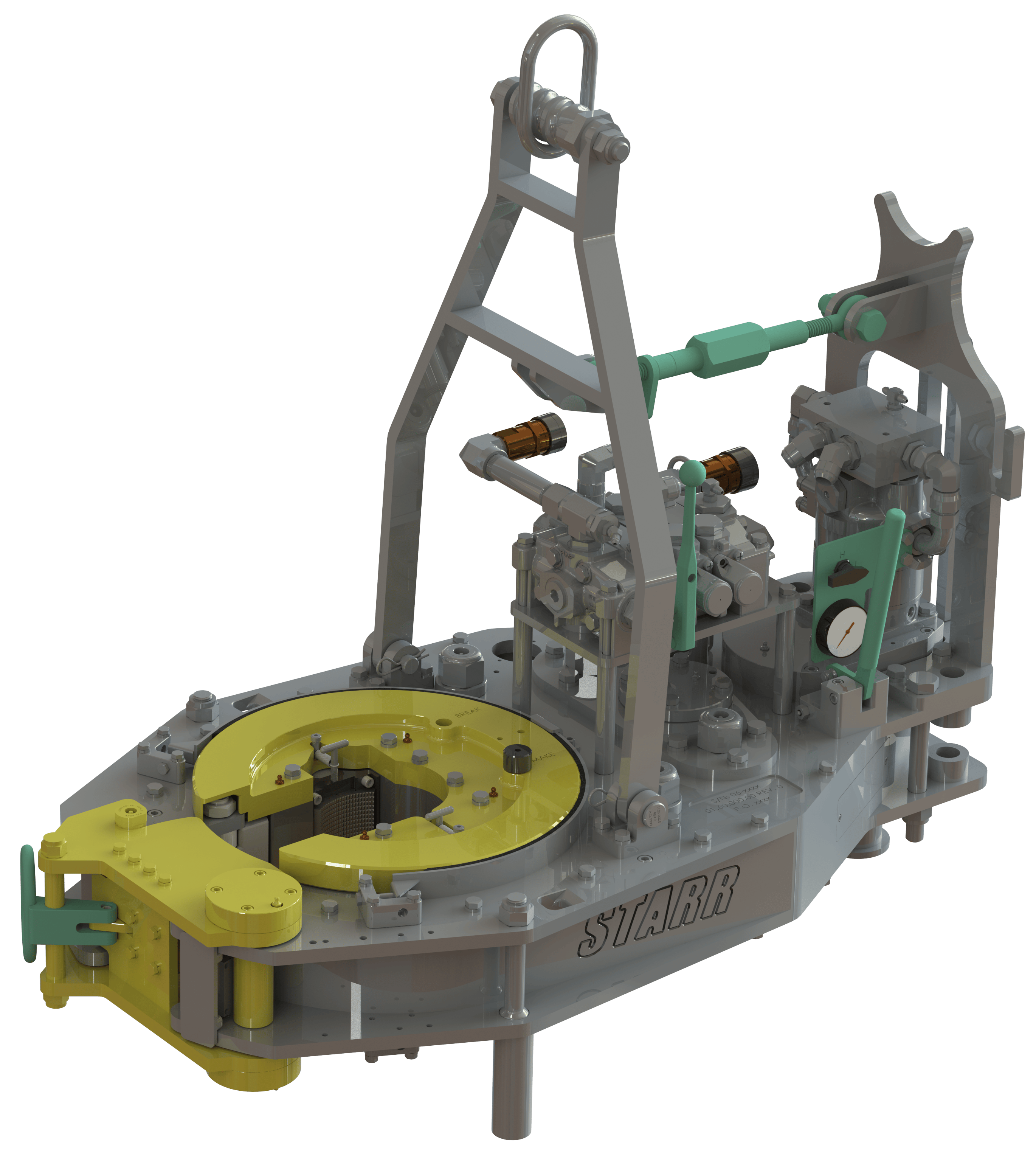
As shown in FIGS. 2B and 2C, rods 112 are connected to the movable jaw 122. The inserts 150 are on fixed jaws 120 and the insert 152 is on a movable jaw 122 (corresponding to the fixed jaws and active jaw, respectively, of the tong of FIG. 1A).
Stops 124 hold jaws 120 and prevent sideways insert movement. The stops 124 may be welded to the jaw or otherwise secured. Removable bolts may be used instead of the stops 124. The stops 126 perform the same functions. A right angled member 127 (FIG. 3C) maintains a roller 135 rotatably in place in holes 123, 125. Holes 129 either receive a projection of an insert to maintain the insert in place or a pin extends through the hole 129 into the insert to accomplish this.
FIGS. 4A-4G illustrate an alternative jaw mounting system in which holders are interposed between jaw bodies and inserts. The holders protect the jaws from damage if the inserts wear down and a variety of different types and/or sizes of inserts may be used with and interchanged on a single holder. In one aspect it is within the scope of this invention to use these holders to mount conventional toothed dies to a tong jaw and to use them for easy substitution of new and/or different dies.
FIG. 4A shows a jaw system 400 for a tong (like the tong of FIG. 2A) which has two fixed jaws 402 and a movable (movable toward and away from a tubular to be gripped 403) jaw 404. Each jaw 402 has a jaw body 405 with a holder 406 secured thereto. In one aspect dovetail keys 407 secured to the holder or releasably mounted thereto fit in corresponding slots 408 of the jaw bodies 405 to releasably mount the holder 406 to the body. In one aspect dovetail keys 409 releasably mount the holders 406 to jaw bodies 405. The dovetail keys 409 are releasably held in corresponding recesses 411 in the holders 406. One or more dovetail keys 409 may be used (two shown for each holder 406).
An insert 420 has dovetail keys 421 received and held in corresponding slots 422 of the holder 414. The insert 420 is shown as a single unitary insert but a plurality of individual inserts (either abutting or spaced apart) may be used secured to the jaw body 415.
FIG. 5A shows a tong system 500 with a tong having a movable rotary 502, fixed jaws 504, 505, and a movable jaw 506 (remainder of tong, not shown, like the tong of FIG. 2A; like the tong of FIG. 1A, but with the added features discussed here). Pins 520 pin the fixed jaws to the rotary. Inserts 522 on the fixed jaws 504, 505 are like the inserts described herein for other fixed jaws. Insert 524 on the movable jaw 506 is like other inserts described herein for movable jaws. A pre-load cylinder 508 to assist in make-up is pivotably connected at one end to the fixed jaw 505 and at the other end to the movable jaw 506. A pre-load cylinder 510 to assist in break-out is pivotably connected at one end to the fixed jaw 504 and at the other end to the movable jaw 506. It is within the scope of this invention for the ends of cylinders connected to the fixed jaws to instead be secured to the rotary or to a support ring or other member that rotates with the rotary. It is within the scope of this invention to employ one cylinder interchangeable between the positions of the cylinders 508 and 510 (FIG. 5A) or one cylinder connectible to the fixed jaw 506 at one end for break-out and at the other end of the fixed jaw 506 for make-up with the other cylinder end secured to the rotary. Rollers 530 rotatably mounted on the movable jaw 506 co-act with cam surfaces 532 on the rotary 502 to move the jaw 506 to operative and inoperative positions.
A control system 600 directs fluid for actuating the pre-load cylinders to and from the cylinders. In a system with one cylinder a simpler control system is used which applies fluid to the cylinder as needed and extracts it therefrom as desired.
The system 600 has a directional control valve 602 that directs fluid from a reservoir 608 in lines 604, 606 to one or both cylinders or from one or both cylinders. An accumulator 610 holds sufficient hydraulic fluid under pressure to maintain desired continuous pressure levels on the pre-load cylinders so that the cylinders maintain the desired pre-load force without interruption or decay due to fluid bleed-off.
Air in a line 640 selectively applied with a control system 650 (e.g. mounted on the rig floor, on the tong or remote controlled) selectively actuates the pump 630 to pump fluid through the valve 602 to the pre-load cylinders. The directional control valve 602 is either manually operated or operated by remote control. Correct fluid pressure is monitored with a gauge 651.
Simultaneously fluid is flowing out in line 635 from the pre-load cylinder 510, allowing its spring 553 to urge its corresponding piston 554 inward into the pre-load cylinder 510 thereby pulling the end of the movable jaw toward the fixed jaw 504 and increase the loading of the jaw 506 on the tubular 650.
As shown in FIG. 5C the tubular 650 has been gripped due to the action of the pre-load cylinder 510 with a suitable pre-load force (e.g., but not limited to, about 500, 1000, 5000, 10000 or 50000 pounds of force). This force is sufficient that when the rotary 502 of the tong is rotated the jaws do not slip on the tubular 650; but the pre-load force is sufficiently low that the jaws do not mark or damage the tubular 650.
FIG. 8 shows schematically a top view of a power tong according to the present invention. A power tong T has an hydraulic motor M with control/monitor apparatus C on a tong case S. A movable jaw J is moved and rotated by a rotary R which is moved by interconnection, via appropriate gearing, by the motor M. Fixed jaws F and G are secured to the rotary R. A first pre-load cylinder D connects the movable jaw J to the fixed jaw G for applying a pre-load to the movable jaw for make-up operations. A second pre-load cylinder L connects the movable jaw J to the fixed jaw F for applying a pre-load to the movable jaw for break-out operations. An insert I (any insert disclosed herein) is secured to the movable jaw J and inserts K (any insert disclosed herein) are secured to the fixed jaws F and G.
FIG. 9 shows a tong jaw 450 according to the present invention with an insert 454 (any insert disclosed herein) and rods 452 secured thereto, e.g. by welding. The rods 452 provide a member to which either a cylinder body or a piston of a pre-load piston cylinder apparatus is connectible. Instead of the rods 452 as shown which extend from above the jaw 450 to a point below it, only rod sections may be used secured to one or both sides of the jaw to provide a securement member for an end of a pre-load apparatus.
According to the present invention a variety of apparatuses and devices may be employed to pre-load a tong jaw having one or more smooth faced gripping insert elements thereon. In one aspect a manually activated pre-load cylinder is used which has fluid or material manually introduced therein to apply a pre-load or manually removed therefrom to release a pre-load. In another aspect a pre-load cylinder is pivotably secured at one end to a rotary or part thereof and the other end is releasably connectible to either end of a movable jaw so that a pre-load may be applied, selectively, to either end of the movable jaw for make-up or break-out operations as desired. In one aspect such a pre-load cylinder has a rod with an end member receivable in and movable in a slot in the movable jaw or there are recesses at either end of the jaw for holding the end member of the rod so that a pre-load can be applied. A secondary small cylinder may be used to selectively move the pre-load cylinder in the jaw slot or it can be moved manually. In another embodiment the tong"s movable jaw has one or more upwardly projecting lugs engageable by a forked piston rod end of a pre-load piston/cylinder that is attached to the rotary. The rotary is rotated so that the jaw is cammed into the pipe to be rotated in a pre-load position and then the forked rod is removed for further tong operations.
In use, two or more jaw assemblies are placed in a tong and are disposed around a length of casing. The jaw assemblies 1001, 1001" are then advanced radially inwardly in the direction of arrows "A" (FIG. 12) until they engage and firmly grip the casing. Because of the flexible construction of the gripping arrangement 1007, the shims 1006 and the arcuate pad 1004, the friction layer 1009 substantially conforms to the circumference of the casing and grips the casing with a substantially uniform gripping action. Once the casing has been firmly gripped the jaws are rotated by the tong in the usual manner. It will be noted that circumferential forces applied to the friction layer are transmitted through the carrier plate 1008 so that any local loads caused, for example by an irregularity in the surface of the casing are redistributed by the carrier plate 1008 and transmitted to the jaw holder 1002 via the side flange 1011 and the arcuate pad 1004 (see FIG. 18).
Various modifications to the embodiment described are envisaged, for example the friction layer 1009 could comprise silica paper, carborundum paper, tungsten carbide paper, or diamond paper, the term "paper" as used herein including cloth. If desired the friction layer 1009 may comprise a layer of flexible material, for example metal, having a surface formed with ridges and valleys similar to the surface of a metal file. Such an arrangement is shown in FIG. 15 where the friction layer has been identified by reference numeral 1009". In this embodiment the friction layer could be bonded to the carrier plate. However, it is conceivable that the carrier plate could be dispensed with since the friction layer 1009" is capable of redistributing circumferential forces itself. If desired the blocks 1005 are disposed with, particularly if the arcuate pad 1004 is made from a relatively firm resilient elastomeric material. The shims 1006 may be dispensed with although they help prevent the resilient elastomeric material of the arcuate pad 1004 being extruded under pressure.
FIG. 16 shows another friction layer 1009" which comprises a perforate screen the exposed surface of which is coated with grit, preferably zircon grit. This arrangement has the advantage that any paint or dirt dislodged from the surface of the casing can be accommodated in the perforations of the screen. Because of the large number of holes in the perforate screen the perforate screen is preferably used in conjunction with a carrier plate 1008 to which it is preferably secured either by adhesive or by soldering or welding. It has also been found desirable to coat the surface of the perforate screen which faces the carrier plate with grit to enhance the transfer of forces therebetween. If desired the carrier plate could conceivably be dispensed with although this is not recommended.
In use, the gripping arrangement 1007 can be rapidly replaced simply by unscrewing the socket screws 1014, removing the end plates 1012 and 1013 together with the gripping arrangement 1007 and installing a new arrangement. Because it is normally essential to minimize replacement time the gripping arrangement 1007 will normally be supplied complete with end plates 1012 and 1013. The gripping arrangement 1007 may be removably mounted on the end plates 1012 and 1013 if desired.
The present invention is useful for gripping casing for rotation. Gripping arrangements in accordance with the present invention may also be used for gripping and rotating other tubulars, for example tubing or drill strings, or for use in slips, for example for supporting a casing string or drill string while lengths are being added thereto or subtracted therefrom.
Referring to FIGS. 19A and 19B of the drawings there is shown a conventional tong assembly which is generally identified by the reference numeral 2001.
The power tong 2002 comprises a pair of gates 2004, 2005 which are held together in the position shown by latch 2006. When the latch 2006 is released the gates 2004, 2005 can be swung open by admitting hydraulic fluid to piston and cylinder assemblies 2007 and 2008. The power tong 2002 also contains a rotary 2009 which is provided with four jaw assemblies 2010. The rotary 2009 can be rotated by a hydraulic motor 2011.
The backup tong 2003 is provided with two gates 2012, 2013 which are held together by latch 2014 but which, when latch 2014 is released can be swung to an open position.
In use, a lower length of casing (not shown), the upper end of which is provided with a socket, is gripped by slips. A stabbing guide is mounted on the socket and the pin of an upper length of casing is lowered into the stabbing guide.
Once the pin is correctly located the stabbing guide is removed. The gates 2004, 2005 of the power tong 2002 and the gates 2012, 2013 of the backup tong 3 are then opened and the tong assembly 2001 moved towards the casing until the lower length of casing lies within the backup tong 2003 and the upper length of casing lies within the power tong 2002. The gates 2004, 2005, 2012, 2013 are then closed and latched. Jaw assemblies in the backup tong are then advanced to engage the lower length of casing while jaw assemblies in the power tong 2002 are advanced to grip the upper length of casing. The hydraulic motor 2011 is then actuated to turn the rotary 2009 and rotate the upper length of casing relative to the lower length of casing. The tong assembly 2001 is supported by a pneumatic lifting cylinder 2015 which enables the power tong 2002 to move towards the backup tong 2003 as the pin enters the socket. Reaction forces are transmitted by columns 2016 disposed to either side of the tong assembly 2001 and by a series of levers in a known manner. It should be noted that the power tong 2002 is free to move in a plane parallel to the backup tong 2003 within certain limits.
Referring now to FIGS. 20A and 20B there is shown an apparatus in accordance with the present invention which is generally identified by the reference numeral 2100.
The apparatus 2100 comprises a tong assembly 2101 which is generally similar to the tong assembly 2001 shown in FIGS. 19A and 19B and parts of the tong assembly 2101 similar to the tong assembly 2001 have been identified by similar reference numerals in the "2100" series.
Turning first to the guide 2117 it will be seen from FIG. 21B that this comprises four identical components 2118 which are bolted to the top of the power tong 2102. As best shown in FIG. 21C each component is tapered so as to guide the pin of an upper casing to the center of the opening of the power tong 2102.
Referring now to FIG. 22, the backup tong 2103 is provided with three prismatic jaw assemblies 2119a, 2119b, and 2119c which, when actuated, hold a lower length of casing 2120 in a fixed position relative to the backup tong 2103.
As shown in FIG. 23 the backup tong 2103 is provided with three upwardly extending locating rods 2121 which are each provided with a conical tip 2122. Similar, the underside of the power tong 2102 is provided with three blocks 2123 each of which is provided with a recess 2124 shaped to receive the conical tip 2122 of a respective locating rod 2121.
In use, the lower length of casing 2120 is first secured by slips on the rig floor in the usual manner. The gates 2112 and 2113 of the backup tong 2103 are then opened and the tong assembly 2101 moved into position with the backup tong 2103 circumjacent the lower length of casing 2120 and immediately below the socket 2125 thereof.
The gates 2112 and 2113 are then closed by hydraulic piston and cylinder assemblies 2126 and 2127 and the latch 2114 closed. The prismatic jaw assembly 2119a is fixed while prismatic jaw assemblies 2119b and 2119c are automatically advanced by a predetermined distance when the latch 2114 is closed. This grips the lower length of casing firmly and also ensures that the backup tong 2003 is in a fixed position relative to the lower length of casing 2120. The position thus far attained is shown in FIG. 23.
At this time pneumatic lifting cylinder 2115 is extended which lowers the backup tong 2003. The conical tips 2122 of the locating rods 2121 enter the recesses 2124 of the blocks 2123 and thus locate the power tong 2002 with respect to the backup tong 2003. This in turn locates the guide 2117 with respect to the lower length of casing 2120 so that the center of the guide 2117 is coaxial with the axis of the lower length of casing 2120. This position is shown in FIG. 24.
The power tong 2102 is then raised so that the blocks 2123 are well clear of the locating rods 2121. At this point the jaw assemblies in the power tong 2102 are applied to the upper length of casing 2128 and the hydraulic motor 2111 actuated to rotate the rotary and screw the pin 2129 into the socket 2125. During the procedure the power tong 2102 moves towards the backup tong 2103. However, even when the joint is tightened to the required torque the blocks 2123 still lie a short distance above the conical tips 2122 of the locating rods 2121.
At this stage the jaw assemblies of both the power tong 2102 and the backup tong 2103 are relaxed, the gates 2104, 2105, 2112 and 2113 opened and the tong assembly 2101 retracted in preparation for the casing being lowered. It will be noted that one component 2118 of the guide 2117 is mounted on each of the gates 2104, 2105 and accordingly the guide 2117 opens and closes with the gates 2104, 2105.
For certain applications a backup tong is not required, for example where the power tong can conveniently be restrained by a chain attached to the drilling tower.
The apparatus 2200 comprises a power tong 2202 which is generally similar to the power tong 2002. The basic construction of the power tong 2202 is similar to the power tong 2002 and parts having similar functions have been identified by the same reference numeral in the "2200" series.
The main differences are that the apparatus 2200 does not include a backup tong and that it is provided with a guide 2217 and a socket centralizer 2230.
In use, the lower length of casing 2220 is first secured by slips (not shown) with the socket 2225 facing upwardly close to the slips. The power tong 2202 is then lowered onto the socket 2225 so that the socket 2225 enters the socket centralizer 2230 and aligns the socket centralizer 2230, the socket 2225 and the guide 2217. The upper length of casing 2228 is then lowered so that its pin 2229 enters the guide 2217, is center there by and enters the socket 2225. At this point power tong 2202 is raised. Its jaw assemblies are then advanced to grip the upper length of casing 2228 which is then rotated to screw the pin 2229 into the socket 2225. Once the joint is tightened to the required torque the gates 2204, 2205 are opened and the power tong 2202 withdrawn.
The embodiment shown in FIG. 29 is generally similar to that shown in FIG. 28 except that the apparatus 2300 also includes a backup tong 2303. Since the upper length of casing 2328 and the lower length of casing 2320 are being aligned by the guide 2317 and the socket centralizer 2330 no special arrangements need be made for aligning the power tong 2302 and the backup tong 2303.
The procedure for connecting the upper length of casing 2328 to the lower length of casing 2320 is as follows. First, the lower length of casing 2320 is secured in slip (not shown). The gates 2312, 2313 of the backup tong are then opened and the apparatus 2300 maneuvered so that the lower length of casing 2320 is disposed within the backup tong 2303. The power tong 2302 is then lowered until the socket 2325 on the lower length of casing 2320 is received within the socket centralizer 2330. The upper length of casing 2328 is then lowered until the pin 2329 passes through guide 2317 and enters the socket 2328. Only at this stage are gates 2312, 2313 closed and the jaw assemblies of the backup tong 2303 activated to grip the lower length of casing 2320. The power tong 2302 is then raised and its jaw assemblies activated to grip the upper length of casing 2328 which is then rotated to cause the pin 2329 to enter the socket 2325 and the joint to be tightened to the desired torque. The jaw assemblies are then relaxed and the gates 2304, 2305, 2312, 2313 of the power tong 2302 and the backup tong 2303 opened prior to retracting the apparatus 2300.
Various modifications to the embodiments described are envisaged, for example, if desired, the guide and the socket centralizer could be mounted on the backup tong 2303 rather than the power tong 2302. Alternatively, the guide could be mounted on the backup tong without a socket centralizer. Such an arrangement is shown in FIG. 30.
The embodiment shown in FIG. 30 is generally similar to that shown in FIG. 19a and 19b and parts of the tong assembly 2401 similar to the tong assembly 2001 have been identified by similar reference numerals in the "2400" series. One difference is that the top of the backup tong 2403 is provided with a guide 2417.
In use, the lower length of casing 2420 is first secured by stops 2431 on the rig floor in the usual manner. The gates 2412 and 2413 of the backup tong 2403 are then opened. Since two of the four components 2418 of the guide 2417 are mounted on the gates 2412 and 2413 the guide 2417 opens with the gates 2412 and 2413 so that the lower length of casing 2420 can enter the backup tong 2403 when the carriage 2432 which supports the apparatus 2400 is advanced towards the casing 2420 on rails 2433. When the lower length of casing 2420 is fully within the backup tong 2403 the gates 2412 and 2413 are closed. The components 2418 of the guide 2417 have a stepped interior (not visible in FIG. 30) so that the lower part of each component 2418 touches the socket on the top of the lower length of casing 2420 whilst the upper part of the interior of each component 2418 tapers inwardly to form a funnel. Once the lower length of casing 2420 has been gripped the upper length of casing 2428 is lowered through the power tong 2402 towards the lower length of casing 2420. The guide 2417 guides the pin on the bottom of the upper length of casing 2428 into the socket. The power tong 2402 is disposed a small distance above the guide 2417. Once the pin of the upper length of casing 2428 has entered the socket on the lower length of casing the jaws of the power tong 2402 are applied to the upper length of casing 2428 which is rotated until the joint reaches the desired torque.
Thus, when the jaw holders 3105 are in the position shown in FIGS. 31 to 37 the jaws 3106 can slide along an arcuate path having a center of curvature at a point 3109 which is radially inwardly of the gripping surface of the gripping elements 3107 but to one side of the center 3110 of the rotary 3100.
In use, when it is desired to grip a tubular 3111, for example a length of casing, the tubular 3111 is introduced into the rotary 3100 through the opening 3112. This is shown in FIG. 31. It should be noted that the jaws 3106 have been displaced to a position where they touch one another at point 3113. This position can be achieved by displacing the jaws 3106 manually. However, in practice the jaws 3106 will normally be found in this position as a result of the exit of the previous tubular as will be described more fully hereinafter.
The rotary 3100 is then rotated clockwise (as viewed in FIG. 34) to advance the jaws 3106 into gripping engagement with the tubular 3111 as will be described herein after. The gripping surface substantially conforms to the surface of the tubular 3111 and thus has a center of curvature at the center 3110 of the rotary 3100 when the jaws 3106 are applied. After the tubular 3111 has been rotated and tightened to the required torque the rotary 3100 is rotated anti-clockwise to allow the jaws 3106 to move away from the tubular 3111 under the influence of spring 3104.
Referring now to FIG. 38, the rotary 3100 is shown fitted in a tong 3116. As shown in FIG. 39 and 40, the rotary 3100 is formed as a one piece casting which comprises a top section 3117, a bottom section 3118, and a peripheral wall 3119 on which is formed a toothed track 3120. Both the top section 3117 and the bottom section 3118 are provided with an elongate slot 3121, 3122 respectively. Each elongate slot 3121, 3122 has its center of curvature on the center of rotation of the rotary 3100.
As can be seen in FIG. 38 and FIGS. 31 to 37, the sides of the rotary 3100 are provided with cams 3128, 3129, 3130 and 3131 which are screwed to the rotary 3100. The rotary 3100 is located in the tong 3116 by nine guide rolls 3132, five of which are visible in FIG. 38. The guide rolls 3132 each have an upper and a lower roller which bears against the peripheral wall 3119 of the rotary 3100 above and below the toothed track 3120 respectively.
In FIG. 38 the tubular 3111 is about to be gripped. (This corresponds to the position shown in FIG. 34.) The hydraulic motor (not shown) is actuated to rotate gear wheels 3133, 3134 and 3135 which in turn rotate the rotary 3100 in a clockwise direction. However, while the rotary 3100 rotates the disk 3123 is restrained by the friction member 3125. The disk 3123 in turn restrains the pivot shaft 3103 and the jaw assembly 3101. Because the jaw assembly 3101 is restrained the jaw units 3102 ride up on the cams 3128, 3130 which urge the jaws 3106 into the tubular 3111 until either the pivot shaft 3103 engages the end of the elongate slot 3121 (or the forces between the tubular 3111, the jaw units 3102 and the cams 3128, 3130 are sufficiently high) at which time the disk 3123 rotates in unison with the rotary 3100 against the friction member 3125. It will be noted that because the centers of curvature of the gripping elements 3107 and the arcuate track 3108 do not coincide the jaw holders 3105 do not spin around the jaws 3106 although means to limit the sliding movement of the jaws 3102 relative to their jaw holders 3105 could be provided if desired.
If it is desired to rotate the tubular 3111 in the opposite direction then the rotary 3100 is simply rotated in the opposite direction causing the rollers 3136 to roll along the cams 3129, 3131.
In conclusion, therefore, it is seen that the present invention and the embodiments disclosed herein and those covered by the appended claims are well adapted to carry out the objectives and obtain the ends set forth. Certain changes can be made in the subject matter without departing from the spirit and the scope of this invention. It is realized that changes are possible within the scope of this invention and it is further intended that each element or step recited in any of the following claims is to be understood as referring to all equivalent elements or steps. The following claims are intended to cover the invention as broadly as legally possible in whatever form it may be utilized. The invention claimed herein is new and novel in accordance with 35 U.S.C. § 102 and satisfies the conditions for patentability in § 102. The invention claimed herein is not obvious in accordance with 35 U.S.C. § 103 and satisfies the conditions for patentability in § 103. This specification and the claims that follow are in accordance with all of the requirements of 35 U.S.C. § 112.
This application claims the benefit under 35 USC §119(e) of U.S. provisional application No. 60/914,562 filed Apr. 27, 2007, which is incorporated by reference herein in its entirety.
The present invention relates to devices for applying torque to tubular members such as drill pipe. In a particular embodiment, the invention relates to transmission systems in power tongs.
Many devices such as power tongs employ a transmission or gear train having different gears (or sets of gears) for operating at different speeds and torque ratios. An example of such a power tong is seen in U.S. Pat. No. 4,631,987, which is incorporated by reference herein in its entirety. In order to run the gear train at different speeds, the power source (e.g., a motor shaft) must selectively engage the different gears in the gear train. This typically entails selectively bringing a drive gear on the motor shaft into engagement with the appropriate set of gears in the gear train in order to run the device at the desired speed.
Transmissions in power tongs are normally less complex than in other machinery such as automobiles. Typical manual automobile transmissions have mechanisms such as a clutch to selectively remove load from the gears and synchronizers to assist the gears in meshing at the same speed. With these mechanisms to assist gear meshing, the shape of the top surface of the gears is not of great consequence and is normally flat.
However, because power tongs do not have complex gear meshing mechanisms and because the gears of the transmission may be stationary when the shift occurs, the largely flat top surface on the teeth of such gears often interferes with the gears meshing smoothly. Operators will typically attempt to run the motor at low speeds to facilitate the meshing of the gears. However, this often leads to the “grinding” of the gears and excessive wear on the gear teeth, particularly if the motor is run at too high of a speed during meshing. It would be a significant improvement in the art to provide a gear system which facilitated meshing in general and in certain examples, facilitated meshing without applying power to the drive gear.
One embodiment of the invention is a power tong having a ring gear, a gear train, a motor and a gear shift mechanism. The gear shift mechanism further includes a linear actuator and a shift arm connect to the linear actuator. A drive gear is positioned on a drive shaft extending from the motor and this drive gear includes an upper and lower set of drive teeth having beveled top portions. The shift arm engages the drive gear between the upper and lower set of drive teeth and movement of the linear actuator causes the drive gear to engage one of at least two gears in the gear train.
Another embodiment of the invention includes a tong body having a top plate and a bottom plate forming a cavity there between. A ring gear and gear train are positioned within the cavity and the gear train includes a high speed and a low speed gear. A motor has a drive shaft extending directly into said cavity and the drive shaft includes a drive gear connected thereon which selectively engages the high speed gear or the low speed gear. A linear actuator is positioned above the top plate with a rod extension projecting into the cavity substantially parallel to the motor drive shaft. A shift arm is operatively connected to the rod extension and capable of moving the drive gear into selective engagement with at least one of the high or low speed gears.
FIG. 1A illustrates a prior art power tong gear shift mechanism 180. The shift mechanism 180 is shown integrated to hydraulic motor 40 with splined drive shaft 190 extending from motor 40. A gear collar 186 having internal splines (hidden from view) will engage the splines on drive shaft 190, but allow gear collar 186 to slide up and down on drive shaft 190. Gear collar 186 includes a drive gear 105 fixed on its lower end which allows drive gear 105 to engage high and low speed gears in a power tong gear train. FIG. 1B, a detail inset of FIG. 1C, illustrates the gear shift mechanism 180 integrated with the gear train 50 of a conventional power tong. From FIG. 1B, it can be seen how gear collar 186 is able to slide up and down drive shaft 40 allowing drive gear 105 to selectively engage either high speed gear 52 and low speed gear 51. In FIG. 1A, gear shift mechanism 180 will move gear collar 186 up and down by way of shift handle 181 operating in conjunction with shift yoke 182. Shift yoke 182 will include a pair of yoke pins 183 which engage the collar groove 184. Although yoke pins 183 ride in collar groove 184, yoke pins 183 do not prevent gear collar 186 from rotating with respect to shift yoke 182. However, when yoke pins 183 move up or down with shift yoke 182, yoke pins 183 will act to move gear collar 186 up or down on drive shaft 190 in order to engage one or the other of high speed gear 52 or low speed gear 51. A detent aperture 187 will allow spring biased detent post 185 to engage detent groove 1186 on drive shaft 190 and selectively hold gear collar 186 at the proper height to engage the low speed gear 51 of gear train 50. Although hidden from view, a similar detent groove will exist to hold gear collar 186 at the correct height to engage high speed gear 52.
FIG. 2B, a detail inset of FIG. 2A, shows one embodiment of the gear shift mechanism 1 of the present invention being used with a power tong gear train 50. Power tong gear train 50 could be any number of conventional or future developed gear trains, but in the particular embodiment of FIG. 2B, gear train 50 includes low speed gear 51 and high speed gear 52. As is known in the art, gear train 50 will drive ring gear 60 causing the power tong to grip and apply torque to pipe, casing, and other tubular members. Gear train 50 is enclosed between bottom plate 62, top plate 61, and side plates, although the side plates and all but a portion of top plate 61 have been removed to illustrate gear train 50.
FIG. 2B"s embodiment of gear shift mechanism 1 will generally include a linear actuator such as shift cylinder 30, shift arm 25, and drive gear 5. In FIG. 2B, shift cylinder 30 is a conventional double acting hydraulic piston and cylinder assembly position on top plate 61. However, many other types of linear actuators could be employed, alternative examples of which are described below in reference to FIGS. 5 to 8. Regarding shift cylinder 30, hydraulic fluid inlets/outlets 31/32 allow hydraulic fluid to enter and exit moving the piston within shift cylinder 30 upwards and downwards. The shifting valve 33 directs fluid to either the top or bottom of the piston within shift cylinder 30. A piston rod extension 35 extends out of shift cylinder 30 and through top plate 61. The shift arm 25 connects to rod extension 35 and engages drive gear 5. As better seen in FIG. 4, shift arm 25 has a fork end 26 which engages a fork groove 8 in drive gear 5. A tong motor 40 is also positioned on top plate 61 and has a motor shaft 41 extending through top plate 61. Typically, tong motor 40 will be hydraulically powered, but other motor types (e.g., electric) could be employed. In this embodiment, motor shaft 41 extends directly into the body of the power tong and engages the gear train 50 with drive gear 5. Motor shaft 41 does not engage any intermediate gears which in turn provide power to a shaft extending into the tong body. In the embodiment illustrated, motor shaft 41 includes a series of splines 42.
As best seen in FIG. 3A, drive gear 5 includes a series of internal spines 15 which allow drive gear 5 to engage spines 42 (see FIG. 4) on motor shaft 41 and to slide up and down on motor shaft 41, but not rotate relative to motor shaft 41. FIG. 3A illustrates how this embodiment of drive gear 5 has an upper set of gear teeth 10 and a lower set of gear teeth 11, with a fork groove 8 formed there between. Although the embodiment of FIGS. 1 to 3 show shift arm 25 having a fork 26 engaging fork groove 8 between upper gear 6 and lower gear 7, the invention could include other connections between shift arm 25 and motor shaft 41. For example, fork groove 8 could be above upper gear 6 or below lower gear 7, although motor shaft 41 may need to be considerably longer than seen in FIG. 2B and modifications made to drive gear 5 so it may engage gears 51 and 52 without interference from shift arm 25. Alternatively, rather than a fork groove, a bearing could be attached to motor shaft 41 and shaft arm 25 be attached to the bearing (allowing motor shaft 41 to rotate with respect to shift arm 25). The shift arm should be considered operatively connected to or operatively engaging the drive gear if the shift arm positions the drive gear using any of the above mechanical arrangements or any other mechanical arrangement allowing the shift arm to directly or indirectly change the position of the drive gear.
Viewing FIG. 3F, a detail inset of FIG. 3A, it can be seen that the top portion 12 of gear teeth 10 and 11 are beveled, forming a top ridge line 13 and sloping side shoulders 14. The base 18 of the teeth connect to the gear body and top ridge line 13 extends radially outward from base 18. The beveled top portion is formed by sloping side shoulders 14 extending from ridge line 13 to the sides 17 of the teeth. As used herein, the “top portion” of the gear teeth 10 and 11 means that portion which first engages another gear when meshing with that other gear. Thus, both sets of gear teeth 10 and 11 have top portions. In the illustrated embodiment, the top portion of the gear teeth are beveled at a 45 degree angle. However, other embodiments could be beveled at any angle between 30 and 60 degrees or even angles less than 30 degrees or more than 60 degrees (or any angle between 0 and 90 degrees). In the embodiments shown, the top portion of the gear teeth are considered fully beveled since the entire length of ridge line 13 has at least one sloping shoulders 14. However, there may be embodiments where something less than the entire length of ridge line 13 has at least one sloping side shoulders, for example, only 75% of ridge line 13 having a sloping side shoulder (or any percentage between 35% and 100% of ridge line 13 having a sloping side shoulder). Nor do the ridge line 13 and sloping shoulders 14 need to form perfectly sharp angles, but could also be somewhat rounded.
In FIG. 3D, upper gear teeth 10 are shown being somewhat offset from lower gear teeth 11 because the upper and lower sets of gears have a different ratio (or number of teeth). However, this is governed by the types of gears the which the upper and lower sets of gears will engage and will vary in different transmission designs. For example, in another embodiment, the two sets of gears may have the same ratio (i.e., not be offset). Whether the two sets of gear teeth are offset is not an important factor in the current invention.
Viewing FIG. 2B, it will be understood that when rod extension 35 moves shift arm 25 upwards, shift arm 25 raises drive gear 5 into engagement with low speed gear 51. As drive gear 5 and low speed gear 51 meet, the beveled top portion 12 of gear teeth 10 will come into contact the bottom of the teeth on low speed gear 51. Because beveled top portion 12 presents the sharp edge of top ridge 13 with sloping shoulders 14 on either side, the teeth of low speed gear 51 should slide down one of the sloping shoulders 14. This will cause drive gear 5 to rotate clockwise or counter-clockwise as it is forced against low speed gear 51. If motor 40 is not under power, shaft 41 (and thus drive gear 5) is free to rotate and drive gear 5 will be able to mesh with low speed gear 51 with a minimum of friction or grinding of teeth edges. Likewise, the same efficient meshing of gears will take place when drive gear 5 moves downward and lower gear teeth 11 engage high speed gear 52.
FIG. 5 is a schematic illustrating one embodiment of a hydraulic system incorporating the tong shift mechanism described above. The hydraulic fluid supply will connect at 151 ato diverter valve 152. Valve 152 supplies fluid to switch valve 154/33 which operates shift cylinder 30 as described above. Line 150 will supply fluid through ball valve 160 to tong door opening and closing cylinder 159. Fluid entering cylinder control valve 155 will supply lift cylinder 156. Both tong door cylinder 159 and lift cylinder 156 pertain to tong operations unrelated to gear shifting and therefore, not shown in the other figures. Fluid entering motor control valve 158 will supply motor 40 via pilot operated shut-off valve 157. FIG. 5 also illustrates relief valve 153 and fluid return outlet at 151 b. Naturally, FIG. 5 illustrates but one hydraulic circuit and many other circuits, hydraulic or otherwise, could be employed.
The shift arm 83 will have a handle 81 on one end and a bolt aperture 88 on the opposite end with an elongated slot 87 in between. The end of shift arm 83 having aperture 88 will be pinned or bolted to a fork in anchor post 74 such that shift arm 83 may rotate with respect to anchor post 74. A second pin or bolt will engage a fork on top of shift rod 75 and pass though elongated slot 87 on shift arm 83. Form this mechanical arrangement, it can clearly be seen how moving shift handle 81 up or down will cause shift rod 75 to move up and down (thus moving drive gear 5 to its various positions engaging a gear train 50 such as seen in FIG. 2B). FIG. 6 also shows a detent groove 78 formed on shift rod 75 and a detent post 86 which extends through an aperture in rod guide collar 73. Although not explicitly shown, it will be understood that a spring or other device will bias detent post 86 inward to contact shift rod 75. In the embodiment shown in FIG. 6 and as is commonly employed in detent post/groove mechanisms, detent groove 78 has a 60° entry/exit chamfer, which allows detent post 86 to engage detent groove 78 and hold shift rod 75 in place against a moderate amount of force, but also allows a larger force to push detent post 86 out of engagement with groove 78. However, in another embodiment, detent groove 78 may have a square shoulder and detent post 86 includes a finger grip to allow an operator to grasp detent post 86 and manually withdraw detent post 86 from engagement with detent groove 78. In the embodiment of shift rod 75 seen in FIG. 6, there will be two detent grooves 78 allowing shift rod 75 to move and temporarily lock between upper and lower position (thereby allowing drive gear 5 to engage the high speed or low speed gears). Naturally, other embodiments could encompass a different number of detent grooves.
FIGS. 6 to 8 illustrate a different embodiment of manual shift mechanism 70. In this embodiment, a more complex shift handle assembly 80 engages anchor post 74 and shift rod 75. The exploded view of FIG. 9 better illustrates the details of shift handle assembly 80. Shift handle assembly 80 includes shift arm 83 having a fixed handle 81 on one end, bolt aperture 88 on the other end, and elongated slot 87 in between. In this embodiment, both aperture 88 and elongated slot 87 are formed on flat surfaces 91 which engage the forks in anchor post 74 and shift rod 75. A detent collar 85 will include detent apertures 89 with detent posts 86 positioned therein. In this embodiment, detent posts 86 need not be biased with springs, but only need be fixed in and protrude from detent apertures 89. Detent collar 85 will also include a sliding handle 82 and a grease fitting 90. A spring 84 will be positioned between detent collar 85 and fixed handle 81 and bias detent collar 85 (and sliding handle 82) away from fixed handle 81. Viewing FIG. 7, it can be seen how not only shift handle assembly 80 is positioned on base plate 79, but also that guide plates 71 are positioned on base plate 79 (see FIG. 8 for second guide plate 71). Guide plates 71 will include slots 76 to accommodate the bolt engaging elongated slot 87 and will have two detent grooves 72 aand 72 b(best seen in FIG. 8). It will be readily apparent that in operation, detent posts 86 will engage detent grooves 72 aor 72 bin order to lock shift arm 83 in an upper or lower position (and correspondingly shift rod 75 and drive gear 5). When it is desired to move shift arm 83 from one position to another, sliding handle 82 will be pulled back toward fixed handle 81 causing detent collar 85 to move toward fixed handle 81 and consequently causing detent posts 86 to become disengaged from the detent grooves 72 aor 72 b. Shift arm 83 is then free move up or down in order to move to the other detent groove and shift drive gear 5 to the other (high or low speed) gear train.
The present invention relates to power tongs typically used in the oil and gas industry to make up and break apart threaded joints on pipe, casing and similar tubular members. In particular, the present invention deals with an improvement to the braking mechanism found on most power tongs. The present invention also deals with a mechanism allowing a power tong operator to reverse, from a remote location, the direction in which the power tong is rotating the tubular members.
Power tongs have been in existence for many years and are generally employed in the oil and gas industry to grip and rotate tubular members, such as drill pipe. It is necessary to grip drill pipe with high compressive forces while applying a high degree of torque in order to break apart or tighten threaded pipe connections. An example of a conventional power tong can be seen in U.S. Pat. No. 4,084,453 to Eckel. Most current power tong designs such as Eckel include an open slot or throat, through which the drill pipe is passed in order to place the power tong in position around the pipe. Typically power tong designs employ a cam mechanism for converting a portion of the torque into a gripping (compressive) force normal to the pipe. This conversion is often accomplished utilizing a power-driven ring gear having an interior cam surface. The ring gear will also have an opening corresponding in size to the throat of the power tong. The ring gear is rotatively positioned between an upper and a lower cage plate which form a jaw carrier. The cage plates are also rotatively positioned in the power tongs and also have openings corresponding with the throat of the power tong. Multiple jaw members are typicall


 8613371530291