
drill pipe pup joint specifications free sample
Every step of production process is performed with the highest degree of accuracy to meet or exceed API Specifications as well as the Industry Standards.
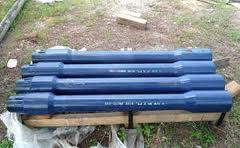
It is a short drill pipe used to adjust the overall length of drill string. The surface of Drill Pipe Pup joint looks like a smaller version of joint of drill pipe.
The minimum yield strength of Drill Pipe Pup Joint is 120000 PSI, just like the Tool Joint of the Drill Pipe. We manufacture Drill Pipe Pup Joints of all sizes, grades, and thread profiles to meet any custom requirements.
All our products have passed the ISO certification and API certifications.We have become the reliable exporter of Drill Pipe Pup Joint in India. Our products are tested numerous times under technical guidance and are made from best quality material.

ABBREVIATIONS AND DEFINITIONS USED ........................................................ 8 6.1 Abbreviations................................................................................................ 8 6.2 Definitions..................................................................................................... 9 6.2.1 Benchmark ...................................................................................... 9 6.2.2 Prove-Up ......................................................................................... 9 6.2.3 Pipe Body........................................................................................ 9 6.2.4 Tool Joints....................................................................................... 9 6.2.5 Connection Break-In ..................................................................... 10 6.2.6 Manufacturer ................................................................................. 10
TRANSOCEAN DRILL PIPE PUP JOINT REQUIREMENTS ............................... 14 8.1 Material....................................................................................................... 14 8.1.1 Pipe Body...................................................................................... 14 8.1.1.1 Integral Pup Joints ........................................................ 14 8.1.1.2 Welded Pup Joints ........................................................ 14 8.1.2 Tool Joints..................................................................................... 15 8.1.2.1 Welded Pup Joints ........................................................ 15 8.1.3 Sour Service Requirements .......................................................... 15 8.2 Manufacturing And Testing......................................................................... 15 8.2.1 Pipe Body And Tool Joints – Mechanical Properties Verification .. 15 8.2.1.1 Tensile Tests................................................................. 15 8.2.1.1.1 Integral Pup Joints ..................................... 15 8.2.1.1.2 Welded Pup Joints ..................................... 16 8.2.1.2 Charpy Impact Tests ...................................................... 17 8.2.1.2.1 Integral Pup Joints ..................................... 17 8.2.1.2.2 Welded Pup Joints ..................................... 17 8.2.1.3 Hardness Tests – Welded Pup Joints ........................... 19 8.2.2 Non-Destructive Examination Of Bar Stock, Pipe Body And Tool Joint – ALL Pup Joints .................................................................. 19 Hardcopies are printed from an electronic system and are not controlled
Pipe Body: Verification Of Upset Geometry – Welded Pup Joints 20 8.2.3.1 Internal Upset Geometry ............................................... 20 8.2.3.2 Internal Upset Geometry Tracing .................................. 21 8.2.3.3 Non-Conformance Of Internal Upset Geometry ............ 21 Pipe Body: Non-Destructive Examination – Welded Pup Joints.... 22 8.2.5.1 Pipe Body Inspection .................................................... 22 8.2.5.2 Reference Standard ...................................................... 22 8.2.5.3 Acceptance Criteria....................................................... 23 8.2.5.4 Magnetic Particle Inspection (MPI) ............................... 24 Tool Joint To Pipe Body Welds: Mechanical Properties And Weld Verification – Welded Pup Joints .................................................. 24 8.2.6.1 Welding Qualification .................................................... 24 8.2.6.2 Tensile Tests................................................................. 25 8.2.6.3 Charpy Impact Tests ..................................................... 25 8.2.6.4 Surface Hardness Tests ............................................... 26 8.2.6.5 Transverse Side Bend Tests ......................................... 26 8.2.6.6 Through-Wall Hardness Tests ...................................... 26 Tool Joint To Pipe Body Welds: Non-Destructive Examination Of Weld Area – Welded Pup Joints ................................................... 27 8.2.7.1 Ultrasonic Inspection ..................................................... 27 8.2.7.2 Magnetic Particle Inspection (MPI) ............................... 27 8.2.7.3 Visual Inspection ........................................................... 28 8.2.7.4 Misalignment Inspection ............................................... 28 Failure To Meet Specified Minimum Chemical, Physical, And Mechanical Property Requirements – ALL Pup Joints .................. 28
GENERAL REQUIREMENTS ............................................................................... 29 9.1 Tool Joints .................................................................................................. 29 9.2 Benchmarks ............................................................................................... 29 9.3 Anti-Galling Treatment ............................................................................... 30 9.4 Connection Break-In ................................................................................... 30
ATTACHMENTS ................................................................................................... 40 Attachment A: Exemption Request Form .............................................................. 40 Attachment B: External Preservative Coatings For New Drill Pipe Pup Joint ........ 40 Attachment C: Connection Thread Preservative For New Drill Pipe Pup Joint ..... 43
PURPOSE This specification provides the requirements for manufacturing, inspection and testing of new drill pipe pup joints purchased by Transocean for use on Transocean rigs to maximize longevity and reliability.
SCOPE This specification was developed as a supplement to API Specifications 5DP, RP 7G, and RP 5A5 covering the manufacturing, inspection and testing of new drill pipe pup joints. If conflicts should arise between this specification and other referenced specifications, the provisions of this specification shall apply. All requests for exemptions to the technical requirements specified herein shall be submitted to the Subject Matter Expert, Tubular Equipment for approval prior to the issuance of any Transocean purchase orders for new or used drill pipe pup joints covered by this specification. 2.1
Exemptions 2.1.1 This specification is prepared in a general format and may not encompass all facets of the manufacturing of new drill pipe pup joints. Therefore, a Manufacturer may request exemption (s) for a particular procedure and/or requirement detailed in this specification. The intent of a formal exemption process is to ensure that when this occasion arises that it is properly managed by ensuring the appropriate level of management is aware of the exemption to the procedure and/or requirement. This allows management to assess the risk prior to issuing approval of the exemption. 2.1.2 The Manufacturer Request for Exemption form (Attachment A) is included and made a part hereof. The form may be revised from time to time by Transocean, and shall be used for all exemption requests. All exemption request forms that have been approved by Transocean shall be included in the documentation package specified in Section 14 herein. If a form is submitted for a specific procedure and/or requirement detailed in this specification, purchase orders shall not be issued until approval of the exemption has been granted by the Transocean Subject Matter Expert, Tubular Equipment. If an exemption request is submitted after the purchase order is issued, the production process involved with such request shall not proceed until approval of the exemption has been granted by the Transocean Subject Matter Expert, Tubular Equipment. 2.1.3 It is the responsibility of the Transocean Subject Matter Expert, Tubular Equipment to ensure that all possible avenues have been Hardcopies are printed from an electronic system and are not controlled
given complete consideration prior to authorizing a “Manufacturer Request for Exemption” to a specific procedure and/or requirement contained herein. Approved exemptions may include qualifications and additional requirements to address any risk that Transocean Subject Matter Expert, Tubular Equipment or their representative may identify that is or could be created as a result of the exemption. 2.1.4 All approved exemptions shall have validity for a specific period of time that shall be solely determined by the Transocean Subject Matter Expert, Tubular Equipment. All past and current approved “Manufacturer Request for Exemption” forms shall be retained by the Transocean Subject Matter Expert, Tubular Equipment and the Manufacturer. Verbal approvals of requests for exemptions may be granted in urgent situations but shall be followed up within 24 hours with an e-mail, and then formalized with a signed copy of the exemption request form within seven days after verbal approval. 2.1.5 At the time this standard is approved there will be some drill pipe pup joints in use or in inventory, which do not meet this specification because the drill pipe these are used with does not meet new Transocean specification. Primarily, the difference will be with the pin and box connection, and in most cases, the connections can simply be recut to comply with the new standard when new drill pipe is ordered. Therefore, in most cases, it will not be necessary to order new drill pipe pup joints when new drill pipe is ordered, unless the new drill pipe is a different size. Supply chain management and all business units shall plan and schedule replacement of such drill pipe pup joints when necessary. Exceptions to this specification may be granted from time to time to meet client requirements that are specific to certain drilling programs that are to be carried out under long-term commitments. If the customer provides non-standard drill pipe, they should be advised to provide the non-standard pup joints that are needed. If it becomes necessary for any reason to purchase any drill pipe pup joints that have been previously manufactured, and does not meet all of the requirements of this specification, a request for a technical review of such drill pipe pup joints shall be submitted to the Transocean Subject Matter Expert, Tubular Equipment prior to the establishment of any purchase commitments.
RESONSIBILITY It is the responsibility of anyone who has the authority to purchase new drill pipe pup joints to ensure that any new drill pipe pup joints purchased for use on Transocean rigs shall meet the technical requirements of this specification unless Hardcopies are printed from an electronic system and are not controlled
REFERENCES The latest edition of the referenced documents (including any amendment) applies, unless specified as a dated reference. HQS-OPS-TIB-516-03 – Replaced by this Equipment Standard (HQS-OPS-ESTDPIP-001), New Drill Pipe Pup Joint Manufacturing Specification API Specification 5DP (Spec 5DP), Specification for Drill Pipe - ISO 11961:2008 (Identical), Petroleum and natural gas industries—Steel drill pipe API Specification 7-2 (Spec 7-2), Specification for Threading and Gauging of Rotary Shouldered Thread Connections - ISO 10424-2:2007 (Identical), Petroleum and natural gas industries—Rotary drilling equipment—Part 2: Threading and gauging of rotary shouldered thread connection API Specification Q1, Specification for Quality Programs for the Petroleum, Petrochemical and Natural Gas Industry - ISO TS 29001:2007 (Identical), Petroleum, petrochemical and natural gas industries—Sector specific requirements—Requirements for product and service supply organizations API Recommended Practice 5A5 (RP 5A5), Field Inspection of New Casing, Tubing, and Plain-end Drill Pipe - ISO 15463:2003 (Identical), Petroleum and natural gas industries—Field inspection of new casing, tubing and plain-end drill pipe API Recommended Practice 7G (RP 7G), Recommended Practice for Drill Stem Design and Operating Limits API Recommended Practice 7G-2 (RP 7G-2), Recommended Practice for Inspection and Classification of Used Drill Stem Elements - ISO 10407-2:2008 (Identical), Petroleum and natural gas industries—Rotary drilling equipment—Part 2: Inspection and classification of used drill stem elements ISO 9001:2008, Quality management systems—Requirements ASTM A370, Standard Test Methods and Definitions for Mechanical Testing of Steel Products Hardcopies are printed from an electronic system and are not controlled
ASTM E23, Standard Test Methods for Notched Bar Impact Testing of Metallic Materials ASTM E709, Standard Guide for Magnetic Particle Testing ASTM E1444, Standard Practice for Magnetic Particle Testing ASME Boilers & Pressure Vessel Code, Section IX NACE MR-01-75, Sulfide Stress Cracking Resistant Metallic Material for Oil Field Equipment - ISO 15156 (Identical), Petroleum and natural gas industries—Materials for use in H2S-containing Environments in oil and gas production HQS-OPS-EST-DPIP-001, Transocean Equipment Standard, New Drill Pipe Manufacturing Specification American Iron and Steel Institute Manufacturers Catalogs
American Iron and Steel Institute American Petroleum Institute American Society for Metals American Society of Mechanical Engineers American Society for Testing and Materials Drilling Engineers Association Headquarters of Transocean located in Houston, TX International Organization for Standardization National Association of Corrosion Engineers Portable Document File used on the Web Server Procedure Qualification Records Property Symbolization System used within Transocean Quality Heath and Safety and Environment Quality Process Control Plan
Definitions 6.2.1 Benchmark Benchmark is a reference mark machined on the pin and box areas adjacent to the shoulder, to determine the amount of material that may be removed from the shoulder when it is refaced. 6.2.2 Prove-Up For the purpose of this specification, the term “prove-up” is an inspection procedure used to verify the nature and extent of an indication (both surface and sub-surface) that is revealed by an automated inspection process. Prove-up involves the use of several types of inspection devices and tools including but not limited to portable compression and/or shearwave ultrasonic devices, electromagnetic examination equipment, dye penetrant materials, and measurements taken by micrometer, dial calipers, etc. If manual “prove-up” inspection fails to reveal the full nature and extent of an indication, the results of the prove-up shall be regarded as inconclusive which are therefore rejectable. 6.2.3 Pipe Body For the purpose of this specification, the term “pipe body” shall be the tube section of a pup joint that is being or has been upset and heattreated to meet API or other special grade requirements as specified in the purchase order. Integral pup joints are machined from one piece of steel, and therefore pipe body is not upset and heat-treated to an API grade specification. Instead, the material of the pipe body in this case is the same material as the tool joints, but the term “pipe body” is still used to describe this part of the pup joint. 6.2.4 Tool Joints One box and one pin tool joint is welded or machine onto each respective end of a pipe body to comprise one finished drill pipe pup joint. Threads and shoulders of specified pin and box connections shall be machined into the tool joints, and sufficient tong space shall Hardcopies are printed from an electronic system and are not controlled
be provided as specified in Table 11. The tong space dimensions specified herein are for the purpose of allowing the proper engagement of tongs to make and break the connection and to provide adequate tong space length to allow a sufficient number of connection re-cuts to maximize the life-cycle of the drill pipe pup joint. Tool joints can be made from forgings or bar stock, the dimensional and material characteristics of which shall meet the requirements specified herein. 6.2.5 Connection Break-In Connection break-in is a process of mating and un-mating newly manufactured pin and box connections for the purpose of coldworking the surfaces of the threads and shoulders prior to delivery of the product by the Manufacturer. The purpose of connection break-in during the course of manufacturing new drill pipe pup joints is to avoid using rig productive time to perform the same procedure on the rig floor. If required, connection break-in shall be prescribed in the Transocean purchase order for new drill pipe pup joints. 6.2.6 Manufacturer The Manufacturer shall be the entity to whom the purchase order is issued for manufacturing drill pipe pup joints to comply with this specification, whether the purchase order is issued directly by Transocean or through a third party.
Transocean (including all of their designated third party representatives) reserves the right of access to the Manufacturer’s facilities and subcontractor’s facilities at any time to witness or observe the manufacturing process, mechanical testing, and all forms of inspection of all drill pipe pup joints made or processed under a purchase order issued by Transocean. Transocean also reserves the right to perform additional nondestructive testing at Transocean’s expense.
The Manufacturer/supplier is responsible for the planning and execution of the delivery of drill pipe pup joints and all raw, semi-finished, and finished material constituents thereof.
During handling, trucking, and other means of transporting drill pipe pup joints being manufactured and delivered under a given Transocean Hardcopies are printed from an electronic system and are not controlled
purchase order, due consideration shall be given to the prevention of damage to the drill pipe pup joints. Prior to receipt of the finished product at the delivery location, the cost to repair or replace any drill pipe pup joints that are damaged while under the care of the Manufacturer or any of his subcontractors shall be borne by the Manufacturer of the drill pipe pup joints specified on the Transocean purchase order. 7.4
Only Manufacturers who carry a current API monogram, and produce written guarantees of their capability of providing drill pipe pup joints made to the requirements specified herein shall be contracted for all future supplies. The Manufacturer shall warrant and shall be responsible for ensuring that all applicable manufacturing, inspection, and testing processes that are performed by their third party subcontractor (s) shall comply with the requirements herein. The Manufacturer shall notify the Transocean Subject Matter Expert, Tubular Equipment and their designated third party representative of any intent to utilize third party subcontractor (s) as soon as the decision is made, along with the identity of the third party subcontractor and when the work will be performed. Such notice shall be submitted to Transocean and their third party representative in sufficient time to allow arrangements to be made to attend and witness such work. The Manufacturer shall ensure that the right of access by Transocean is afforded by all of their subcontractors. Transocean reserves the right to reject any drill pipe that has been manufactured or otherwise processed by a third party subcontractor without prior approval or without adequate opportunity to witness the work.
In the event that the Manufacturer intends to utilize materials in their inventory that have been previously processed without being witnessed by Transocean or their third party representative, the Manufacturer shall provide documentation to verify that the material meets the requirements specified herein. In addition, the Manufacturer shall, upon request, perform additional testing and inspection to the material in question to the satisfaction of Transocean and their third party representative to verify that such material meets the requirements of this specification, and is otherwise suitable for use in manufacturing finished drill pipe pup joints under a given Transocean purchase order.
All significant processes involving all forms of heating, forging, machining, welding, inspection, and testing operations, including all related sub-contracted activities The manufacturing sequence Applicable specifications and standards Acceptance and rejection criteria Verification documents and certification Manufacturer’s inspection activities and space for the identification of Customer inspection activities. The production schedule to meet the required delivery
Subsequent revisions to the QPCP are subject to prior approval by Transocean or their representative. From time to time, Transocean may request the Manufacturer to arrange for and attend a Production Meeting prior to commencement of the manufacturing process for the purpose of reviewing and confirming the relevant specifications, purchase order requirements, and the QPCP that applies to each order to ensure agreement is confirmed. The Manufacturer shall take minutes of such Production Meetings, and shall distribute it to all participants after the meeting. Transocean’s customer representatives may attend these meetings. 7.7
All revisions made to approved quality systems, quality process control plans, or procedure specifications shall be submitted to Transocean or their representative for approval prior to any revisions going into effect for any Transocean purchase order. All QPCPs, routing sheets, or other internal documentation shall be made available to Transocean’s third party representative (s) for the purpose of scheduling their attendance and witnessing of selected processes. The Manufacturer shall inform Transocean’s third party representative (s) of all revisions to the manufacturing schedule to ensure prior arrangements to attend or witness such processes can be revised to suit.
Raw materials from China or materials processed in China shall not be used for the manufacture of any drill pipe pup joint intended to be supplied under any purchase order issued by Transocean unless prior approval is obtained from the Transocean Subject Matter Expert, Tubular Equipment. Reviews required to obtain such approval shall include all information necessary, as determined by the Transocean Subject Matter Expert, Tubular Equipment to verify that such raw materials and any material processing shall meet or exceed the requirements specified herein. The Manufacturer shall provide Hardcopies are printed from an electronic system and are not controlled
Each finished drill pipe pup joint shall be legibly paint stenciled on the outer diameter surface of the pipe body with the following information: (a) (b) (c) (d) (e) (f)
Unique number that is traceable to the applicable mill heat numbers of the pipe body and/or tool joint materials Shoulder-to-shoulder length (ft. and tenths of a foot) Nominal size of pipe body Specified nominal wall thickness of pipe body Specified grade of pipe body material Manufacturer’s name or mark
7.10 The shoulder-to-shoulder length required for all drill pipe pup joints shall be specified in the Transocean purchase order. 7.11 Traceability to the applicable mill heat numbers shall be maintained throughout the manufacturing process of the pipe body and tool joint materials. For welded pup joints, a “position” number or other unique sequence number shall be die-stamped onto the end of the pipe body immediately after upsetting and prior to heat treatment to maintain traceability and to represent the order in which the pipe bodies enter and exit the heat-treatment process. A legible unique number shall be applied to the pipe body after heat treatment and prior to FLUT/EMI inspection, and such unique number shall be maintained onto the pipe body throughout the remaining manufacturing processes in order to maintain traceability. The ends of the pipe to which the pin or box shall be affixed shall be stenciled after heat-treatment and prior to FLUT/EMI inspection in order to satisfy the requirements contained in Section 8.2.5.1. It is realized that the process described above of maintaining traceability by the use and marking of unique numbers to the pipe body may differ from one Manufacturer to another, and as such, specific procedures shall be reviewed and approved by the Transocean representative to ensure they satisfy the intent of this section. For integral pup joints traceability shall also be maintained throughout the manufacturing process by the stamping of a unique number to the end of the bar stock prior to heat treatment. Thereafter, such unique number shall be paint-stenciled onto the pipe body, and shall remain legible until final inspection.
TRANSOCEAN DRILL PIPE PUP JOINT REQUIREMENTS Drill pipe pup joints may either be machined from one solid bar of steel, or by welding pin and box tool joints to a central pipe body. When pup joints are supplied in lengths fifteen (15) feet or less they shall be machined as integral lengths from solid alloy bar stock. All pup joint pipe bodies shall be manufactured in accordance with API Spec 5DP, with exceptions defined below. 8.1
Integral Pup Joints When a pup joint is manufactured from bar stock, the material used shall be of AISI 4145H or 4147H or a Transocean approved equivalent. The maximum Phosphorous and Sulfur content of this bar stock shall be 0.015%, and 0.010% respectively.
Welded Pup Joints For pup joints which have tool joints welded to a central pipe body, they should be manufactured in accordance with Transocean Equipment Standard HQS-OPS-ESTDPIP-001, for new drill pipe. The maximum Phosphorous and Sulfur content of drill pipe pup joint steel chemistry shall be 0.015%, and 0.010% respectively. Grade V pipe bodies of drill pipe pup joints of welded construction shall possess the same physical properties as required herein and by API Spec 5DP for API Grade S135 drill pipe, with the exception of the following:
If the Manufacturer specified in the purchase order intends to process drill pipe pup joints using green tubes, upset tubes, or upset and heat-treated pipe bodies, or bar stock that has been supplied by another Manufacturer, prior to any manufacturing a review and written approval by Transocean is required. Such materials may be subject to additional destructive testing at the option of Transocean including all applicable traceability documentation.
Welded Pup Joints Tool joints that are to be welded to a central pipe body shall be manufactured from forged material that meets the minimum requirements herein and in accordance with API Spec 5DP, with exception of chemical composition. The maximum Phosphorous and Sulfur content of tool joint steel chemistry shall be 0.015%, and 0.010% respectively. If tool joints are manufactured from bar stock, they shall be fabricated using AISI 4130 modified material (Timken M7) or an equivalent, which shall be subject to review and approval prior to manufacture by the Transocean Subject Matter Expert, Tubular Equipment.
8.1.3 Sour Service Requirements Pipe bodies that are upset and heat-treated to a specific grade (G, S, or V) for the purpose of being welded to tool joints in accordance with this specification shall be quenched and tempered, which is a requirement in NACE MR-01-75. However, drill pipe pup joints made to this specification should not be construed to be qualified for sour service. Requisitions for drill pipe pup joints intended for sour service shall be ordered on a case-by-case basis after sufficient review of the specific drilling conditions has been completed, and the optimum manufacturing specifications have been designated and approved by the Transocean Subject Matter Expert, Tubular Equipment. 8.2
Tensile Tests 8.2.1.1.1 Integral Pup Joints When bar stock is used to fabricate pup joints as integral, the mechanical properties must comply with the yield/tensile strength requirements detailed in API Spec 5DP, for drill pipe tool joints. Mechanical test specimens shall be machined from the beginning and end of each heat of
material to be used for manufacturing the drill pipe pup joints. The test specimen shall be in the longitudinal direction, at a minimum of 25.4 mm (1 inch) from the outside surface. When the pipe body wall thickness will not accommodate the specimen to be taken at 25.4 mm (1 inch) from the outside surface, the specimen shall be machined from a mid-wall location. 8.2.1.1.2 Welded Pup Joints For pup joints, which has tool joints welded to a central tube body, the yield/tensile strength of the tool joints shall meet the requirements defined in API Spec 5DP, for drill pipe tool joints. The yield/tensile strength of the pipe body shall be conducted per ASTM A307, and shall meet the physical properties specified in API Spec 5DP, and any additional requirements specified herein. Tensile test specimens shall be machined following upsetting and heat treatment, and shall be removed from the pipe body and upset. Pipe body test samples shall be removed from alternate ends of the pipe bodies. Mechanical test specimens shall be machined from the material to be used for manufacturing the pup joint at a frequency of one test per each lot, or one test for every 100, whichever is smaller. This test frequency shall include material used for both the tool joints and central pipe body. The test specimen shall be in the longitudinal direction, at a minimum of 25.4 mm (1 inch) from the outside surface. When the pipe body wall thickness will not accommodate the specimen to be taken at 25.4 mm (1 inch) from the outside surface, the specimen shall be machined from a mid-wall location. When testing tool joints, tensile tests shall be performed in accordance with API Spec 5DP, except where any lot of tool joints consists entirely of boxes. If any lot consists entirely of boxes the tensile test specimens shall be taken from a mid-wall location with the center of the Hardcopies are printed from an electronic system and are not controlled
specimen located at the approximate area of the thread run-out. Results shall meet the specified requirements of API Spec 5DP, for drill pipe tool joints. 8.2.1.2
Charpy Impact Tests 8.2.1.2.1 Integral Pup Joints Charpy testing shall be performed in accordance with ASTM A370 and ASTM E23. Specimens shall be taken from the beginning and end of each heat treatment lot. One set of 3 full size (10.0 x 10.0 mm) specimens shall be taken in the longitudinal direction if wall thickness permits. If full-sized specimens are not obtainable, the largest obtainable sub-sized specimens shall be substituted. All impact tests shall be performed at -20°C. All Charpy Impact values revealed from testing shall met or exceed the minimum values specified in Table 8.2.1.2.1.
Welded Pup Joints Pup joint pipe bodies and tool joints shall be Charpy Impact V-notch tested per ASTM A370 and ASTM E23. Charpy Impact tests are to be taken from the material to be used for manufacturing the pup joint at a frequency of one test per each lot, or one test for every 100, whichever is smaller. This test frequency shall
include material used for both the tool joints and central pipe body. A test shall consist of three specimens. Specimens shall be longitudinally oriented with radially oriented notches. Following upsetting and heat treating, pipe body specimens shall be taken in lots of three from a single location on the pipe body and upset. Pipe body test samples shall be removed from alternate ends of the pipe bodies. Tool joint specimens shall be taken from mid-wall locations. Full-sized (10mm x 10mm) specimens shall be used if wall thickness permits. If full-sized specimens are not obtainable, the largest obtainable sub-sized specimens shall be substituted. All impact tests shall be performed at -20°C. All Charpy Impact values revealed from testing shall meet or exceed the minimum values specified in Table 8.2.2.2.A and Table 8.2.2.2.B, respectively. Table 8.2.2.2.A Pipe Body Minimum Charpy Impact Requirements
Hardness Tests – Welded Pup Joints Brinell hardness tests shall be performed after heat treatment of tool joints and shall not be less than 285 HB (30 Rc) and no greater than 341 HB (37 Rc). Brinell hardness tests are to be performed on the finished OD surface of each tool joint.
All bar stock used to manufacture tool joints or integral drill pipe pup joint lengths shall be inspected using the Full Length Ultrasonic Test method (FLUT). The FLUT shall be performed after the bar stock is bored/trepanned and heattreated. The machined surfaces of all connections shall be inspected via wet magnetic particle inspection after all final machining. All surface indications shall be cause for rejection.
The reference standard used for calibration of the ultrasonic equipment used for the inspection of bar stock intended for the manufacture of integral pup joints shall have longitudinal and transverse notches machined in the OD and ID. The notches shall be machined to a depth of 5%, + 1% of the wall thickness of the bar stock prior to machining. The reference standard shall be made from ultrasonically defect-free material with the same pipe body OD, wall thickness, surface finish, and acoustic properties as the product being manufactured. All indication(s) shall be cause for rejection unless it can be demonstrated to the Transocean representative that the material where the
After final machining, a bi-directional wet florescent magnetic particle inspection shall be completed on both the OD and ID of each tool joint to reveal longitudinal and transverse defects. The magnetic particle inspection process shall conform to the requirements specified in ASTM E1444.
Internal Upset Geometry The internal upset geometry for internal upset (IU), and internal-external upset (IEU) drill pipe shall have a minimum finished Miu length of 4” (101.6 mm) and a minimum radius of curvature between internal upset and pipe body ID of 8” (228.6 mm). The actual internal upset geometry shall be evaluated using a device, which will provide a trace of the MIU length and radius. In some cases where the ID of the tool joint, and the ID of the pipe body are close to the same dimension and only a slight internal upset is required to manufacture the pipe, the 4-inch minimum length requirement shall be waived upon review and approval by the Transocean representative. The 8inch radius specified in Figure 8.2.3.1 below shall always apply to any internal upset.
Pipe Body Inspection The evaluation of pipe body defects shall be performed after final heat treatment using ultrasonic (UT) and electromagnetic inspection (EMI) methods with Tuboscope “Truscope AS” (or equivalent equipment as approved by Transocean representative prior to the inspection) from upset to upset and shall be calibrated and operated at optimum sensitivity levels. Sufficient transducers shall be provided and used during calibration and inspection to reveal both right and left hand oblique-oriented defects in both leading and lagging positions as depicted in Figure 8.2.5.2. All surfaces of the pipe shall be free of scale, pitting, upset wrinkles, and “elephant hide” to be acceptable for ultrasonic evaluation in accordance with the Transocean representative. The location of the minimum wall thickness revealed by the above inspection equipment of each pipe body shall be identified by specifying the distance from the from the end of the pipe that has been marked to be either the pin or box end and recorded in the documentation required in Section 14. Manual prove-up with compression wave U.T. wall thickness readings at the location of the minimum wall thickness indicated by the inspection equipment specified above shall be completed on a minimum of 10% of the pipe bodies from each heat.
Reference Standard A reference standard shall be used to calibrate UT and EMI inspection equipment. The reference standard shall be made from ultrasonically defect-free material with the same nominal OD, nominal wall thickness, surface finish, and acoustic properties as the drill pipe being inspected. Notches shall be machined into the ID and OD surfaces of the reference standard to a depth of 5%, +/- 1% of the specified nominal pipe body wall thickness. The length of each notch shall be between ½ and 1½ inches (12.7 and 38.1 mm). Notches shall be applied on the ID and OD surfaces. They shall be oriented longitudinally (parallel to the pipe axis), transversely (perpendicular to the pipe axis), and obliquely at 11 and 22 degrees to the pipe centerline. Oblique notches shall be machined in both right hand and left hand orientations in both leading and lagging positions as shown in Figure 8.2.5.2. The reference standard shall
Acceptance Criteria Surface indications shall be removed by sanding or grinding. The remaining wall thickness after removal of any surface indications shall exceed 95% of the specified nominal pipe body wall thickness. The removal of any surface indication that results in reducing the remaining pipe body wall thickness below 95% of the specified nominal pipe body wall thickness shall be cause for rejection. Surface indications remaining after grinding to these limits shall also be cause for rejection. Any indication (surface or sub-surface) that produces a signal equal to or greater than the threshold level established with any notch in the reference standard shall be re-evaluated via manual prove-up. Manual prove-up shall include, but not be limited to the use of portable shear wave ultrasonic instruments, electromagnetic examination, or measurements taken by micrometer, dial calipers, etc. The results of such manual prove-up shall be conclusive based on the criteria specified above. All inconclusive indications and mid-body wall indications that cannot be verified via manual prove-up shall be cause for rejection.
Magnetic Particle Inspection (MPI) After final heat treatment, all pipe body ends (from end to 18”) shall be examined via magnetic particle inspection method. The OD surface of the pipe ends shall be examined via wet fluorescent magnetic particle inspection, and the ID surface shall be examined via dry magnetic particle inspection incorporating adequate lighting and mechanical/optical aids to provide adequate visibility of the surfaces to be examined to the satisfaction of the Transocean representative. If scale or other surface condition has formed on the upset surfaces to an extent such that indications may be obscured from view, the surfaces shall be cleaned sufficiently to allow a conclusive inspection to be carried out. In the event that there is a disagreement concerning the suitability of the surfaces to be examined, either before or after cleaning, the Transocean representative shall make the final decision. All surface indications on upsets shall be removed by grinding, sanding, or machining to the limits established by API Spec 5DP, and/or the Manufacturer’s specifications, whichever is the more stringent. MPI shall be performed again after any grinding, sanding, or machining is completed to ensure the indication has been completely removed. Any indications found by MPI after removing the maximum amount of material allowed shall be cause for rejection of the joint. Additionally, any sub-surface indication that cannot be manually proven-up shall be cause for rejection of the joint.
Welding Qualification Welds between the tool joint and the pipe body shall be performed in accordance with an approved welding procedure specification (WPS), procedure qualification records (PQR), and welder performance qualifications (WPQ) written and qualified in accordance with the Manufacturer’s documented procedures that include acceptance criteria to verify the weld design requirements are met. The WPS shall describe all essential and nonessential variables to control before, during, and after the welding process. The PQR shall record all essential variables of the welding process. Tool joint to pipe body
Tensile Tests Tensile tests shall be performed to the weld area material between the tool joints and the pipe body per ASTM A370. Test specimens shall be taken from the mid-body wall area and longitudinally oriented, with the weld within the gage length of the specimen as specified in API Spec 5DP. The tensile capacity of the weld shall exceed 110% of the corresponding pipe body tensile capacity based on the nominal OD at 100% of the specified nominal wall thickness at the specified minimum yield strength of the material. Tool joint to pipe body weld tensile tests shall be performed at the start of production and on one out of every 100 production welds thereafter.
Charpy Impact Tests Tool joint to pipe body welds shall be Charpy Impact Vnotch tested per ASTM A370 and ASTM E23. All Charpy Impact values revealed from testing shall meet or exceed the minimum values specified in Table 8.2.6.3 below. A single test shall consist of three test specimens. Specimens shall be longitudinally oriented with radially oriented notches and shall be taken from mid-wall locations. Specimens shall be notched at the weld line as detailed in API Spec 5DP. Full-sized (10mm x 10mm) specimens shall be used if wall thickness permits. If fullsized specimens are not obtainable, the largest obtainable sub-sized specimens shall be substituted. All impact tests shall be performed at -20°C. Tool joint to pipe body weld Charpy impact tests shall be performed at the start of production and on one out of every 100 production welds thereafter.
Surface Hardness Tests Surface Hardness tests shall be performed on each tool joint to pipe body weld in accordance with API Spec 5DP. Tool joint to pipe body weld surface hardness tests shall be performed on every weld.
Transverse Side Bend Tests Transverse side bend tests shall be performed on tool joint to pipe body welds in accordance with API Spec 5DP. Further, no cracks shall be allowed. There shall be no signs of separation at the fusion line on either the root or the face. Minimal tearing of the edges shall be acceptable, but shall be less than 1/4" (6.35 mm). Tool joint to pipe body weld transverse side bend tests shall be performed at the start of production and on one out of every 100 production welds thereafter. One test shall consist of two specimens removed from the weld zone of the test piece.
Through-Wall Hardness Tests Through-wall hardness tests shall be performed on tool joint to pipe body welds in accordance with API Spec 5DP, and shall not exceed 37 Rc. Three sets of readings shall be taken; one set close to the ID, one set close to the OD, and one set at mid section. Each set shall include at least two readings in each HAZ on either side of the fusion line. One reading from each set shall be in the unaffected pipe and tool joint material.
Tool joint to pipe body through-wall hardness tests shall be performed at the start of production and on one out of every 100 production welds thereafter. 8.2.7 Tool Joint To Pipe Body Welds: Non-Destructive Examination Of Weld Area – Welded Pup Joints 8.2.7.1
Ultrasonic Inspection All tool joint to pipe body welds shall be ultrasonically inspected using the shear wave technique. Ultrasonic instrument sensitivity shall be set using a calibration standard of the same material, curvature, acoustic properties, surface finish and wall thickness as the welded material. The instrument reference level shall be established at 80% FSH (Full Screen Height) using a 1/16” (1.59 mm) diameter drilled hole. The instrument gain shall be set at 6db (6 decibels) above the reference gain setting. The full volume of the weld and heat affected zone (HAZ) shall be scanned twice from the pipe body side of the weld. Any flaw indication that exceeds 50% of the screen height shall be cause for prove-up inspection. Such prove-up inspection shall be carried out at reference. Any nonconclusive indication revealed by prove-up inspection that cannot otherwise be physically or visually examined and subsequently removed shall be cause for rejection of the joint, which includes all sub-surface indications.
Magnetic Particle Inspection (MPI) All tool joint to pipe body weld OD surfaces shall be inspected using the wet florescent magnetic particle inspection process. This inspection process shall encompass the weld zone and a minimum of 6" (101.6 mm) on both sides of the weld. Additionally, a dry magnetic particle inspection shall be performed on the ID surface of the weld zone and a minimum of 6" (101.6 mm) on both sides of the weld. The ID inspection shall incorporate a lighted telescoping inspection mirror. All indications shall be removed by grinding and shall be contoured to the adjacent surfaces to the satisfaction of the Transocean representative. Removal of indications by grinding in all cases shall be confirmed by repeating the magnetic particle inspection of the area in question. Any remaining indications that cannot be removed by grinding, sanding, or machining without reducing the integrity of the weld and/or
Tool Joints 9.1.1 The tool joint OD and ID dimensions shall meet the requirement specified in Table 11. 9.1.2 Integral Pup Joints: For pup joints that are made of a single piece of bar stock, the tong space lengths shall be no less than 15 inches. For rigs using high capacity elevators, there will not be sufficient pipe body length to engage such elevators for pups that are only 5 ft. long, shoulder-to-shoulder. In these cases, a different combination of pup lengths needs to be devised to achieve proper space out. 9.1.3 Welded Pup Joints: The pin and box tool joint tong space lengths for pup joints of welded construction shall be manufactured to the lengths specified in Table 11. 9.1.4 Unless specified otherwise in the Transocean purchase order, an 18 degree elevator taper shall be applied to both the box and pin tool joint.
Benchmarks Benchmarks showing the location of the original shoulder shall be applied to each pin and box. Benchmarks shall be visible for a full 360° around the pin or box circumference. The examples of the benchmarks for the pin and box connections that are illustrated in Figure 9.2 below are patented. Therefore, a licensing agreement with the patent holder shall be in place before these specific benchmarks can be machined on tool joints supplied to Transocean. Alternative tool joint benchmarks are subject to prior review and approval by the Transocean Subject Matter Expert, Tubular Equipment prior to machining them onto any tool joints supplied under any Transocean purchase order.
requirements specified in the procedures specified below as a minimum. Exceptions taken to the steps outlined below shall be submitted to the Transocean representative for review and approval prior to performing connection break-in. 1. Clean, visually inspect, and dry both pin and box thread and seal areas for damage and proper anti-gall treatment as specified in Section 9.3. 2. If no damage is apparent, apply Jet-Lube Kopr-Kote thread compound to all threads and shoulder seal surfaces. 3. Make up connection to the maximum torque value as calculated by Farr’s Screw Jack formula per API RP 7G. 4. Break out connection slowly. If the break-out torque exceeds that of the make-up torque, the connection shall be cleaned and examined for damage. If break-out torque is less than make-up torque and there is no damage is apparent, re-apply thread compound. 5. Make up connection a second time to the maximum torque value. 6. Break out connection slowly. If the break-out torque exceeds that of the make-up torque the connection shall be cleaned and examined for damage. If break-out torque is less than make-up torque and there is no damage is apparent, re-apply thread compound. 7. Make up connection a third time to the maximum torque value. 8. Break out connection slowly. 9. Clean the connection (environmentally-friendly iso-parafinnic solvents are preferred). 10. Perform visual inspection of the threads and mating shoulder surfaces and mark and set aside all joints with surface damage for reprocessing. All connections that must be reprocessed shall have phosphate antigalling treatment re-applied to all newly machined or ground surfaces, and shall be subjected to connection break-in procedures again until no damage is detected during or after break-in. 11. Apply Jet-Lube Korr-Guard (see Attachment C) to all threads and mating shoulder surfaces. Preservative may be applied later, subject to the approval by the Transocean representative. The Manufacturer shall repair all corroded surfaces that are deemed unfit for service as determined by the Transocean representative. Hardcopies are printed from an electronic system and are not controlled
MARKINGS In addition to the API Spec 5DP marking requirements shown in Figure 10.A, the Transocean designated joint serial numbers shall be die-stamped on the following surfaces of the pin: -
The Transocean joint serial numbers shall be assigned at the time of issuance of the purchase order, and shall be accordance with the following: 1st Letter:
Manufacturer designated as follows: A = Tenaris (NKK) B = VAM Drilling (USA) C = VAM Drilling (France) D = Grant Prideco (USA) E = Texas Steel Conversion (no longer Smith) F = Rotary Drilling Tools G = Grant Prideco (China)
Note: Some special pipe body grades may require more than one letter. In addition to the marking requirements shown in Figure 10.A, pin tool joints shall have milled slots where the Transocean joint serial number, nominal drill pipe size, weight code, and grade (if welded) shall also be die-stamped in accordance with Figure 10.B. For integral pup joints, no pipe body grade designation shall be stamped. Note: Nominal pipe size shall be expressed by two numbers. Fractions shall be expressed by the number of eighths of an inch. For example, 54 = 5-1/2”, and 65=6-5/8” Hardcopies are printed from an electronic system and are not controlled
To provide easy visual identification of the designated grade and weight for each size of drill pipe pup joint, external grooves and mill slots shall be machined into the pin tool joints. The figures detailed in Section 10 of Transocean Equipment Standard HQS-OPS-EST-DPIP-001 (New Drill Pipe Manufacturing Specification), provide the location and dimensional requirements for the grooves and mill slots. The tables that accompany the figures (Tables 10.C through 10.J) provide the Nominal Pipe body OD, Nominal Weight, and the Specified Nominal Wall Thickness for each pipe body grade and wall designation for which this groove and mill slot configuration shall be applied. It shall be understood that for integral pup joints, the yield strength of the pipe body material is the same as for the tool joints, which is 120 Ksi. All integral pup joints shall be made with a uniform ID throughout the length of the joint that matches the ID dimension of the pin connection specified for the drill pipe that the pup is intended to be utilized. Table 11 provides the ID dimensions that shall apply.
CONFIGURATIONS AND DIMENSIONS The following table specifies the standard sizes and configurations for all welded and integral pup joints. All drill pipe pup joints manufactured for inventory purposes shall be made to the configurations herein unless otherwise exempted by the procedure specified in Section 2.1. Table 11 - Drill Pip Pup Joint Configurations Welded Pup Tong Space Length
External Corrosion Protection The outer surface of each pup joint shall be coated with one of the products listed below and as described in detail in Attachment B of this specification. Alternative products may be submitted for review and approval by the Transocean Subject Matter Expert, Tubular Equipment prior to use.
Internal Corrosion Protection When specified on the Transocean purchase order, Tuboscope TK-34XT or TK-34P shall be applied to the inner diameter of each pup joint length in accordance with Tuboscope’s standard operating procedures and the requirements specified below. 12.2.1 Non-Destructive Examination Of Internal Coating The total dry film thickness of the coating shall be in the range of 127 to 225 µm (0.005 to 0.009 mils) for the products identified above. For alternative products that have been approved for application, the finished dry film thickness shall be within the range specified by the coating manufacturer’s specification and as approved by Transocean. Each pup joint length shall be visually inspected to ensure that the coated surfaces have a smooth finish and are free from visible defects such as blisters, foreign inclusions, sags, runs, etc. The coating shall be holiday tested with a wet sponge holiday detector. The holiday detector shall be checked or calibrated before testing starts and at least once for every one-hundred pipes tested. Acceptance and rejection criteria shall be in accordance with Tuboscope’s standard operating procedures.
Thread Protection All thread protectors shall be Drill-Tec or MSI Magnum, high-density polyethylene or poly-carbonate, non-metallic, composite-reinforced thread Hardcopies are printed from an electronic system and are not controlled
protectors. No substitutions shall be allowed. All thread protectors shall be installed wrench tight to ensure there is no gap between the primary shoulder of the connection and the thread protector. Prior to the installation of thread protectors required by this specification, all surfaces of the threads and shoulders of the pin and box connections on each joint shall be coated with Jet-Lube Korr-Guard preservative as specified herein (see Attachment C for details on these products). Alternative products may be submitted for review and approval by Subject Matter Expert, Tubular Equipment prior to use.
FINAL INSPECTION All finished drill pipe pup joints shall undergo a final-inspection by the Manufacturer with the Transocean representative in attendance. The final inspection shall include verification of the following by visual inspection with the findings, including any exceptions specified in the purchase order recorded and included as part of the documentation package required by Section 14. a. All surfaces of the threads and shoulders of each pin and box connection have been coated with the preservative specified herein (see Attachment C). b. Connections are fitted with the thread protectors specified in Section 12.3. c. All serial numbers shall be legibly stamped, are not duplicated, with no missing numbers unless the Manufacturer an account for such missing numbers caused by rejection of any joints for any reason after the joint serial numbers have been die-stamped. d. Connection damage to threads or shoulders is not present. e. Connections have had anti-gall treatment applied properly (Section 9.3). f. Pup joint lengths roll evenly on the rack and are straight in accordance with API Spec 5DP requirements. g. The entire pup joint surface has been coated in accordance with the requirements specified herein. h. Connections have had Make-up and Break-out performed if specified in the relevant purchase order. i. Pin tool joint markings and die-stamping in the milled slot shall be applied in accordance with the requirements specified herein. Transocean joint serial numbers die-stamped on the pin land and the mill slot shall be verified to be the Hardcopies are printed from an electronic system and are not controlled
Upon completion of all manufacturing and either on or before invoice submittal, the Manufacturer shall supply a document package covering the material supplied as specified herein. Companies manufacturing new drill pipe pup joints under a Transocean purchase order shall provide the documentation that contains the information specified below (electronic documentation unless specified on purchase order). Vendors supplying drill pipe pup joints under a Transocean purchase order who are not Manufacturers (as defined by this specification) shall supply the same documentation required herein. 14.1.1 General Information a. Manufacturer b. Transocean Purchase Order Number c. Manufacturer’s API Specification Certificate, i.e., Spec Q1, Spec 7-2, Spec 5DP, etc. d. Manufacturer’s ISO 9001 certificates, if applicable e. Manufacturer’s Work/Job Order Number f. Date of Manufacture (date of completion) g. Pup Joint Description: (OD, Grade, wall thickness, shoulder-toshoulder length, connection type, connection OD/ID, tong space, etc. h. Internal Coating Type: (Tuboscope TK34XT or TK-34P, etc.) i. Type of Thread Compound Applied j. Type of Anti-Gall Treatment Applied k. Make and Type of Thread Protectors fitted l. Preservative applied to the Pipe OD? Yes ____ No ____ m. Jet-Lube Korr-Guard applied to connections? Yes ___ No ___
14.1.2 List of each drill pipe pup joint with the following: a. Joint Serial Number (each joint provided with this purchase order) b. Shoulder to Shoulder length (in feet and tenths of a foot) c. For welded pup joints, min. wall thickness of pipe bodies via FLUT + Prove-out (thousandths of an inch) for each pup joint, and location of Min. Wall Thickness (distance from pin or box shoulder) – Note: Pin and/or box end shall be paint stencilled after pipe is upset and heat-treated to grade requirements and prior to FLUT inspection. d. Mill Name and Heat No. (for welded pups, this could include separate information for the pipe body, pin, and box) 14.1.3 Pipe Body Information: a. Yield Strength (psi) b. Tensile Strength (psi) c. Elongation (%) d. Charpy “V” Notch Toughness Value (Min. ft.-lbs. value @ -20 deg. C) e. Pipe Body Hardness (Rockwell C or Brinell Hardness for welded only) f. Upset Traces w/Pro-Check Tool 14.1.4 Tool Joint Information a. Connection Size/Type b. OD and ID (to nearest 1/32") c. Bevel Diameter (to nearest 1/32") d. Yield Strength (psi) for all Pins and Boxes e. Tensile Strength (psi) for all Pins and Boxes f. Elongation (%)for all Pins and Boxes g. Charpy “V” Notch Toughness Value (Min. ft.-lbs. value @ -20 deg. C) h. Actual Length of Tong Space (to the nearest 1/16", including hardbanded areas, measured from the shoulder to the 18 degree taper) Hardcopies are printed from an electronic system and are not controlled
In addition to the above, the Manufacturer or supplier shall certify in writing that the unique identity of each drill pipe pup joint that is shipped under a Transocean purchase order is traceable to its corresponding documentation and the physical and chemical requirement of the applicable manufacturing specifications have been met.
Attachment B: External Preservative Coatings For New Drill Pipe Pup Joint PRODUCT DATA SHEET PLUSCO 372 Black WATER REDUCIBLE COATING PLUSCO 372 BLACK COATING is designed specifically for use in Oil Country Tubular Goods in storage. It is a water reducible, fast drying coating with an 18-25 minute STT. The clear, semi glossy film keeps pipes looking mill new, and allows easy recognition of color codes stencils, or other markings, which are so important in identifying the pipe in storage racks. PLUSCO meets the air control standards for a LOW VOC coating while providing the performance long associated with conventional solvent-based products. The latest technology for safe protective coatings has been used to provide the oil industry with a product, which they can use safely. TYPICAL SPECIFICATIONS: Type Resin:
Drill pipe joint is an important connecting component of petroleum drilling pipe drill, which is widely used in oil drilling industry. The market demand is big, has broad prospects for development, Goldenman company with its unique perspective, to create a modern international joint industry as the goal, take on the hard road of entrepreneurship. In the increasingly competitive market economy situation, the courage to struggle and thrive.
Drill pipe joint is an important connecting component of petroleum drilling pipe drill, which is widely used in oil drilling industry. The market demand is big, has broad prospects for development, Goldenman company with its unique perspective, to create a modern international joint industry as the goal, take on the hard road of entrepreneurship. In the increasingly competitive market economy situation, the courage to struggle and thrive.

The RIG will be mobilized from XXX to XXX. The rig will be moored in approximately xxx’ water depth. A string of 36” x 1.5” and 1.0" wall structure pipe will be jetted to xxx’ TVD / MD (xxx’ BML). The shallow hazards survey indicates possible low risk shallow gas potential from the mudline to approx. xxx’ TVD (xxx’ BML) and negligible to moderate risk shallow water flow potential at xxx’ TVD / MD (xxx’ BML).
After jetting the 36” structure pipe to the desired depth, the Drill Ahead Tool (DAT) will be used to drill 26” hole to xxx’ TVD / MD (xxx’ BML) and 20” casing will be run and cemented. The shallow water flow study indicates only low to moderate potential for over-pressured sands through this interval. Should a shallow flow be encountered while drilling riserless, 16.0 ppg kill mud will be available on the rig to control any such flow. After running and cementing 20” casing, the subsea BOP stack and riser will be run and tested. Prior to drilling out of the 20” casing, the hole will be displaced with 10.0 ppg synthetic based mud. A LOT of 10.7 ppg is expected at the 20” casing shoe. LWD (GR/RES/APWD/DIR) will be utilized in this hole section.
A 17’’ x 20” hole will be drilled to xxx’ TVD / MD and 16” casing will be run and cemented. This casing string is being set at this depth based on pore pressure and frac gradient. The expected mud weight at casing point is 10.4 ppg and the expected LOT at the 16” casing shoe is 12.4 ppg EMW. LWD (GR/RES/APWD/DIR) will be utilized in this hole section.
A 14 1/2’’ x 17 1/2” hole will be drilled to xxx’ TVD / xxx’ MD. The KOP for the directional work is planned at 7300" TVD/MD. A major azimuth change while building hole angle will be accomplished in this section using rotary steerable tools. A full string of 13 5/8” casing will be set. The expected mud weight at casing point is 12.0 ppg and the expected LOT at the 13 5/8” casing shoe is 14.2 ppg EMW. LWD (GR/RES/APWD/DIR) will be utilized in this hole section.
A 12 1/4’’ x 15" directional hole will then be drilled utilizing rotary steerable tools and LWD (GR/RES/APWD/DEN/NEUT/DIR) to xxx" TVD / xxx" MD. The 1st target zone will be encountered in this hole section at xxx" TVD. A wireline logging program consisting of GR/Dipole Sonic, RCI, and SWC will be run in this hole section. An 9 7/8" liner will be set in this hole section. The expected mud weight at casing point is 13.0 ppg and the expected LOT at the 11 7/8” casing shoe is 14.9 ppg EMW.
A 9 7/8’’ x 12 1/4" directional hole will then be drilled utilizing rotary steerable tools and LWD (GR/RES/APWD/DEN/NEUT/DIR) to xxx" TVD / xxx" MD. The primary target zones will be encountered in this hole section at xxx" TVD and xxx" TVD. A wireline logging program consisting of GR/Dipole Sonic, RCI, and SWC will be run in this hole section. A 9 7


 8613371530291