
perforated pup joint definition free sample
We are Supplier and Exporter of Perforated Pup Joints in UAE. It is usually installed between the bottom of two nipples of a completion. It allows unrestricted fluid or gas flow, which increases the accuracy and reliability of acquired downhole production data.
We supply all sizes, grades, and thread profiles to meet custom requirements. The perforated pup joints are sometimes also known as the perforated production tube. All our products have passed the ISO certification and API certifications. Our products are tested numerous times under technical guidance and are made from the best quality material.
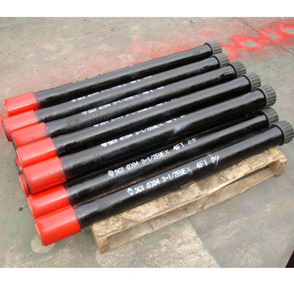
A pup joint is Casing, Pipe or Tubing shorter in length than a standard tubular string. This allows for the adjustment and installation of tools and various tubular components when placement downhole is critical for a specific project. A Spacer Pipe is another reference used to identify pup joints. Pup joint features consist of connections, lengths, weights and material grade.
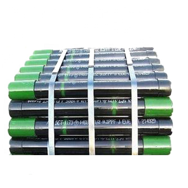
Crossover pup joints are manufactured from seamless mechanical tube. As with all Crossover products, each piece is marked with a distinctive job number and heat number that is fully traceable. A complete range of sizes (1" to 4.5"), weights (standard or heavy wall), and grades (J-55, N-80, L-80, and P-110) are commonly available from stock in 2", 3", 4", 6", 10", and 12" lengths. Lengths up to 20" are available upon request.
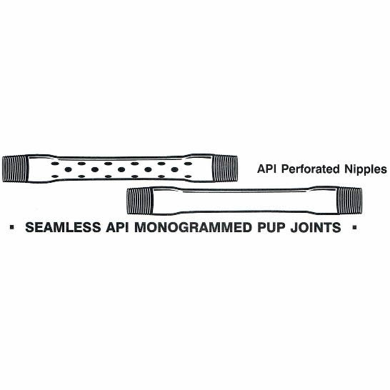
Seamless pup joints with premium connections are available in API and exotic alloy grades. Premium ends are threaded by the manufacturer or authorized licensee.
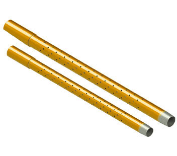
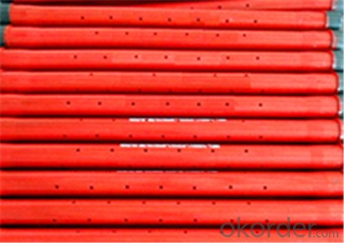
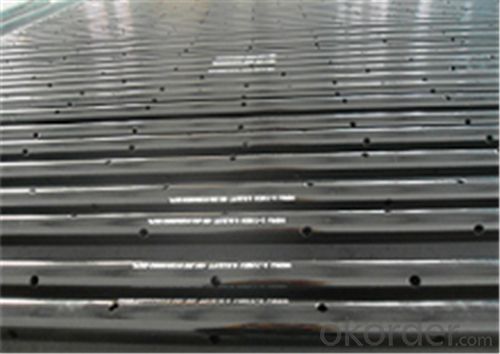
Available with standard or special perforation spacings. Each joint has four rows of ⅜ inch holes drilled longitudinally along the tube. Optional patterns, hole size, and lengths furnished upon request.
A blast joint is shorter in length than standard tubular joint. Built with a heavy wall pipe it is incorporated in the production string to facilitate production across any perforated interval and zone. Blast Joints are manufactured to the following specs connections, lengths, weights and material grade.
Crossover Blast Joints are heavy wall pin by box connectors used in tubing strings and are designed to minimize the effect of external erosive action caused by production fluids. Blast joints are located opposite the location of perforations in the production casing or just below the tubing hanger in sand frac designs. Crossover blast joints are manufactured from seamless mechanical tube in sizes ranging from 2 3/8” to 4 1/2” OD. Any length, grade of material, and threading is available at the customers request. Typical lengths are 10" and 20". Both API and Premium threads are available.
Crossover Coarse Thread Tubing Safety Joint provides for emergency recovery of the major portion of the tubing string should it become necessary to abandon the equipment below. Precision left-hand threads facilitate the release of the joint by right-hand tubing rotation. Equipment requiring right-hand rotation should not be used below the Safety joint.
Crossover Straight-Pull/Shear-Out Safety Joint is used between packers in dual and triple completions and in selective completions using Hydrostatic Single-String Packers. It is also used when rotational releasing is not desired. When ran above the upper packer in a single-string completion, however, the shear value should be adjusted to compensate for any hydraulic conditions that exist when the string is landed, or that are created by well treating operations. They are available in keyed and non-keyed configurations.
Crossover rotary shoes are manufactured from specially tempered steel to provide the ultimate in toughness and durability. They are used to cut a clearance between the fish and the wall of the well bore. Each shoe is tailored to fit a particular downhole need and normally is run on the bottom of one or more joints of washover pipe. Shoe design is dictated by whether it cuts on the bottom, on the OD, on the ID, or any combination of these. When hole sizes permit, additional clearances can be cut using side ribs, thus providing greater circulation.
In wells flowing large volumes, a restriction in the tubing such as a gauge hanger, could cause false pressure readings. Vibrations due to flow could also cause extensive damage to delicate gauges, therefore a perforated pup joint (approx. 10ft length) set above the bomb hanger nipple would allow flow to pass unrestricted over the gauges and hanger, thus giving a more accurate pressure/temperature recording within the
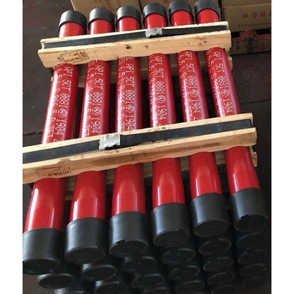
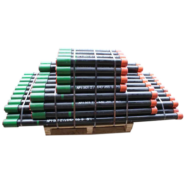
These J55, L80, N80Q & P110 pup joints are manufactured from seamless Grade J-55, L80 N80Q and P110 mechanical tubing. The API 5CT tubing pup joint is mainly used to adjust the height of the tubing strings. It is also used to adjust the depth of down-hole tools.
n: 1. a material used in a cylinder on rotating shafts of an engine or pump in the stuffing box of a valve, or between flange joints to maintain a leak proof seal. 2. the specially fabricated filling in packed fractionation columns and absorbers.
n: 1. a well completion method in which the producing zone or zones are cased through, cemented, and perforated to allow fluid flow into the wellbore. 2. a well completed by this method.
n: a special type of nuclear log that measures the depth of each casing collar. Knowing the depth of the collars makes it easy to determine the exact depth of the formation to be perforated by correlating casing-collar depth with formation depth.
v: 1. to use the drawworks to lift the bit (or other tool) off bottom by raising the drill stem. 2. to use an air hoist to lift a tool, a joint of drill pipe, or other piece of equipment.
The tool body 50 is formed from a tubing joint 52 having a perforated pup joint 54 connected thereto and a central passage 56 closed at its lower end 58.
Inflatable packers 62, 64 are mounted on the outside of the tool body 50, spaced on either side of the perforations 55 in the pup joint 54 so as to define an isolation interval when inflated in the borehole. The spacing of the packers 62, 64 can be set at the surface according to the assumed extent of the zone of the formation to be tested. If it is desired to make test in a borehole with zones of substantially different extent, an alternative arrangement includes a slip joint in the tool body between the packers as is shown in Figure 7. This allows the spacing to be set downhole as will be explained in further detail below. The packers 62, 64 are inflated using pressurised nitrogen gas which is supplied from the surface via a supply line 66. Appropriate valve controls allow selective inflation and deflation of one or other packer. A weak point 68 is provided in the supply line 66 to allow it to be detached should the tool become stuck in the borehole. An alternative to using nitrogen to inflate the packers is to provide a pump which pumps borehole fluids to the packers to inflate them and has a choke to release fluids. This can be connected to the same engine as the main pump such that when the main pump is run, fluid is pumped continuously to the packers and the choke continuously vents the fluid to the borehole while maintaining pressure in the packers. Thus when the main pump operates, the packers set (fluid is pumped into the packer at a greater rate than it leaves through the choke), and when it stops, the packers release (fluid in the packers vents through the choke).
In the embodiment of Figure7, in which a slip joint 94 is positioned between the packers 62", 64", deployment is slightly different. The tool is run into the borehole as before until the correct depth is reached. At this point, the slip joint is fully extended. The lower packer 64" is then inflated just below the bottom of the zone to be tested. The tool is then lowered until the upper packer 62" is just above the top of the zone to be tested and this is then set also. There are a number of ways to achieve the sequential setting of the packers. Two control lines to the nitrogen supply can be used which allows completely independent operation of the packers.
In one embodiment of the present invention, a packer is located below the submersible pump. The packer may be a straddle type packer, wherein the straddle packer has a pup joint in between that allows fluid from the outside to enter the pup joint. The pup joint that allows fluid from the outside to enter the pup joint may be a perforated or slotted pup joint situated in between the straddle packer.
An alternate apparatus of the present invention may have one packer and further comprise a pup joint that allows fluid from the outside to enter the pup joint and a swab cup or flow restrictor assembly below the pup joint.
The apparatus has at least one sensor located inside the joint below the packer or located inside the joint above the pup joint in between the straddle packer that allows fluid to enter. The sensors are selected from a group of sensors that measure pressure, temperature, flowrate, spectroscopy, viscosity, H2S concentration, CO2 concentration, bubble count, a dielectric property, gas/oil ratio, water/gas ratio, water/oil ratio and gamma ray radiation.
FIG. 3 depicts an exemplary embodiment of the present invention, wherein an example of a coiled tubing bottomhole assembly for the current invention is shown. The bottomhole assembly is lowered into the wellbore and positioned in place in front of the formation to be studied by coiled tubing 30. The submersible pump cable 31 is lowered along with the coiled tubing 30 to provide power to the submersible pump 32 and to allow communication between the sensors housed in the bottomhole assembly and the surface processing unit. The sensors may be housed above, below or in the submersible pump. In the example shown in FIG. 3, the sensors 38 are housed in a pup joint above the joint 35 that is designed to allow fluid to enter the system. Joint 35 is designed to allow fluid to enter the system and it is often called a perforated or slotted pup joint. In the present example embodiment shown in FIG. 3, a safety valve 33 is deployed below the pump, the safety valve can be closed if needed to restrict fluid from entering the coiled tubing. This is a common safety practice within the industry. Below the safety valve 33, an emergency release sub 39 is depicted. A shear activated release sub is commonly used. Its function is to release the assembly situated above the emergency release sub 39, should the operation need to do so (for example a stuck packer 34), from the assembly situated below the emergency release sub 39 hence freeing the coiled tubing 30 to be retrieved to surface. Also shown in FIG. 3 is a packer 34 to isolate the open formation 36 to be tested, the packer 34 can be replaced by a swab cup or seal cup assembly. Below packer 34 are a series of joints, the number and length of joints will depend on the length of the open formation to be tested plus a predetermined extra length of joints to provide a safety margin. Among these joints is a joint that allows fluid to enter the bottomhole assembly. To straddle the formation 36 to be tested, a swab cup or seal cup assembly 37, as shown in FIG. 3, can be used; alternatively a second packer (i.e. a straddle packer, not shown) can be used replacing the shown swab cup assembly.
While the invention is described through the above exemplary embodiments, it will be understood by those of ordinary skill in the art that modification to and variation of the illustrated embodiments may be made without departing from the inventive concepts herein disclosed. It would be possible, for instance, to use a battery operated pump and a wireless communication system to start the test; a fluid sample chamber may be lowered into the wellbore; seal cups or swab cup assemblies can be used instead of packer or straddle packer; the position of the sensors, emergency release sub, packers, pup joints, safety valves, etc can vary in it relative position to each other and the amount thereof used in the string as described in the above exemplary embodiments. Accordingly, the invention should not be viewed as limited except by the scope of the appended claims.
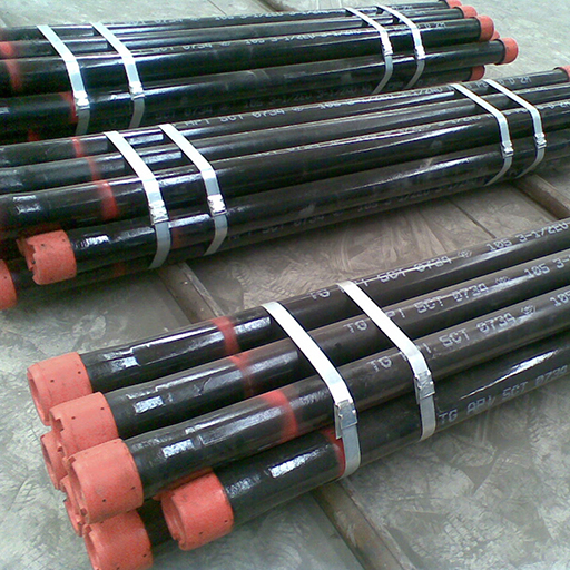
Figure 7. Example of variable choke valve with a unibolt (or wellhead) design. To help illustrate the flow path and quality of the steel, a section of the device has been removed. If you look closely, you can see where the two union joint halves meet; it contains a seal ring like the ones you would see on a wellhead section, and/or a Christmas tree. This allows the seal to withstand high pressures of up to several thousand pounds.(Cooper Cameron Valves)


 8613371530291