
perforated pup joint function quotation
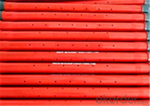
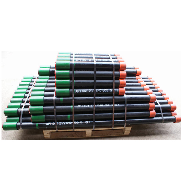
We are Supplier and Exporter of Perforated Pup Joints in UAE. It is usually installed between the bottom of two nipples of a completion. It allows unrestricted fluid or gas flow, which increases the accuracy and reliability of acquired downhole production data.
We supply all sizes, grades, and thread profiles to meet custom requirements. The perforated pup joints are sometimes also known as the perforated production tube. All our products have passed the ISO certification and API certifications. Our products are tested numerous times under technical guidance and are made from the best quality material.

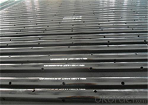
In wells flowing large volumes, a restriction in the tubing such as a gauge hanger, could cause false pressure readings. Vibrations due to flow could also cause extensive damage to delicate gauges, therefore a perforated pup joint (approx. 10ft length) set above the bomb hanger nipple would allow flow to pass unrestricted over the gauges and hanger, thus giving a more accurate pressure/temperature recording within the
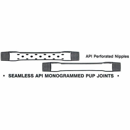
We manufacture pup joints in all sizes, grades, and thread profiles to meet any requirement. Our tubing pup joints are manufactured out of seamless tubing and machined or upset to final dimensions. All API casing and tubing pup joints are manufactured according to API Spec 5CT. Special requirements are available on request.
Our range of products include Blank Adapter SH-500-A, Box-Box Flow Coupling SH502-FC, Combination Adapter SH-500-A, Combination Flow Coupling SH502-FC, Coupled Pup Joint SH503-PJ and Open Hole Hydraulic Set Packer SH518-OHP.
The Bullnose is a blanking device used at the end of the string. Its primary function is to prevent flow from entering the bottom end of the string, whilst its rounded nose design provides a positives guide while running in hole. Bull noses come in standard tool joint thread configurations and can be modified on location to best fit the application for which they are being used.
A pup joint is Casing, Pipe or Tubing shorter in length than a standard tubular string. This allows for the adjustment and installation of tools and various tubular components when placement downhole is critical for a specific project. A Spacer Pipe is another reference used to identify pup joints. Pup joint features consist of connections, lengths, weights and material grade.
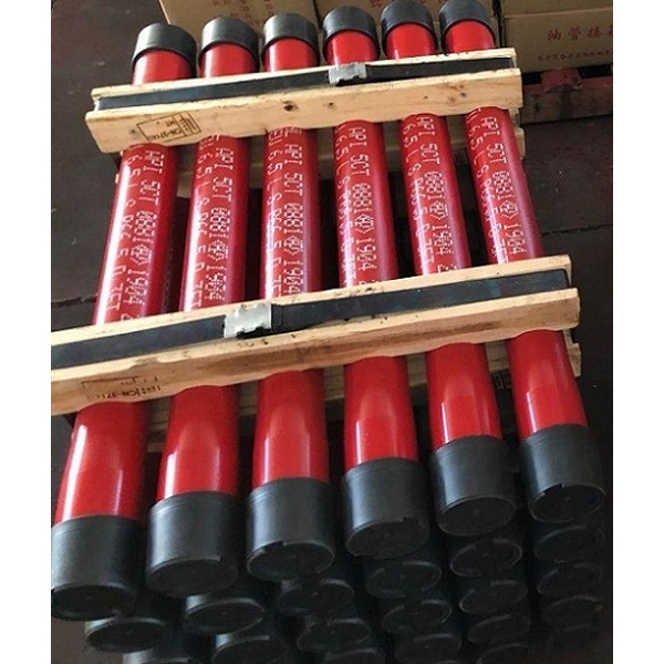
Pup Joints are manufactured from AISI 4145H or 4140H-modified alloy, heat-treated to Hardness range of 285-341 with a Charpy "V" notch minimum impact strength of 40 ft/lb at 70° F and one inch below the surface. Pup Joints are heat-treated to 110,000 PSI minimum yield. All connections are phosphate coated to impede galling during initial make-up.
Disclosed herein is a system for enhancing the recovery of gas in a perforated interval of a gas well. The system features a tubing string having a dead string attached for reducing the flow area of the annulus in the perforated interval, thereby reducing the critical velocity of the gas, i.e., the velocity required to overcome backpressure due to fluids in the well column. The system includes a ported member for receiving gas from the annulus into the tubing string. The ported member and the dead string are isolated from each other by a retrievable plug. The disclosed system provides access from the surface through the dead string for diagnostic or corrective operations. The system also provides delivery of reagents such as foamers to the perforated region to further reduce the critical velocity.
The invention relates to the recovery of natural gas from natural gas wells and more particularly concerns an apparatus for reducing the critical velocity required to unload extended perforated intervals in liquid-loaded gas wells.
FIG. 1 illustrates a production tubing string 13 deployed in a cased natural gas wellbore 101 having an extended perforated interval 102. The production rate of a natural gas well is a function of the pressure differential between the underground reservoir and the well head. This differential is decreased by back pressure against the reservoir pressure. As natural gas and associated liquids are extracted during production, a gradual loss of reservoir pressure occurs in some natural gas wells, thus decreasing the pressure differential. Natural gas wells produce liquids such as water and hydrocarbon. Removal of these produced liquids depends on the velocity of the gas stream produced from the formation. As reservoir pressure and flow potential decrease, there is a corresponding drop in the flow velocity of the natural gas through the production tubing to the well head. Eventually, when the flow velocity becomes insufficient to overcome the “fall back” velocity of the liquids, a column of liquids accumulates in the well bore. This phenomenon referred to as liquid loading decreases the production of the well because the weight of the fluid column above the producing formation causes additional back pressure, which the reservoir must overcome. The critical velocity is the flow velocity or flow rate(mcf/d) required to overcome this pressure differential needed to lift produced fluids to surface.
FIG. 2 illustrates one of the methods that have been used in the art to overcome the problem of liquid loading. Production tubing 13 is extended to include a ported tubing section 17 and a “dead string” 14. Ported tubing section 17 can be a length of production tubing, for example one joint of production tubing or a smaller length of tubing i.e., a pup joint, having holes 18 drilled therein. The inner diameter (ID) of production tubing section 13 and the ID of dead string 14 are isolated from each other by plug 15. Alternatively, this design can include a “bull plug” on the bottom of dead string 14 to force the flow up to the ported section 17. Thus, fluids do not flow through the ID of dead string 14. Rather, the function of dead string 14 is to decrease the area of the annular space 106 between the dead string and the face of the wellbore (or casing). During operation, gas and formation fluids 11 in perforated interval 102 flow in the annular region 106 around dead string 14. Dead string 14 typically has a larger outer diameter (OD) than production tubing section 13, though the dead string 14 can also be the same size as the production tubing 13. For example, in a well with 4½″ casing having an ID of 4″, the production string might have an OD of 2⅜″ and the dead string might have an OD of 2⅞″. Dead string 14 reduces the flow area in the perforated interval, thereby decreasing the required flow rates (critical velocities) to lift produced liquid in the wellbore to surface and reduce the effects of liquid loading. Formation fluids and gas 11 cross over into the production tubing section 13 via holes 18 in ported tubing section 17.
Perforated regions of a gas well often produce sand, which can stick to the tubing (i.e., to dead string 14 inside the casing), fill the tubing, or fill the wellbore below the dead string 14. Several actions that well operators would typically perform to diagnose and correct these sand problems are not possible with the apparatus illustrated in FIG. 2. and other dead string installations or designs known in the art. For example, plug 15 isolating the dead string from the production string (or a permanent “bull plug” on the bottom of dead string 14, as mentioned above) prevents an operator from accessing the wellbore below the apparatus. Thus the operator lacks the ability to run a wireline to the bottom of the wellbore to check for sand fill levels below the dead string 14. Also, when a tubing string becomes stuck in sand or when the bottom of tubing string becomes filled with sand, i.e., “sanded in,” an operator typically tries to establish fluid flow to the bottom of the tubing string and back up through the annular region to disengage the string from the sand. This operation is not possible with the configuration illustrated in FIG. 2 because the holes in 17 can not be isolated and the bull plug would prevents the ability to get circulation fluids to the bottom of the production tubing.
Another deficiency in the configuration illustrated in FIG. 2 is that perforated tubing section 17 limits an operator"s ability run fluid down the annular region between the tubing and the casing to the bottom of the wellbore because such fluids would tend to cross over into the ID of the tubing via holes 18. Thus, the configuration illustrated in FIG. 2 severely limits an operator"s ability to access regions of the wellbore below plug 15, for example, to deliver chemical foamer to the end of the dead string.
The presently disclosed apparatus provides a dead string for reducing the critical velocity of gas produced in a perforated interval of a gas well while still providing the well operator with the ability to access the well bore below the dead string. The apparatus features a tubing string extending into the gas well and having a ported member co-axially disposed within the tubing string. Typical ported members include sliding sleeve valves or ported flow subs, which are described in more detail below. The ported member will typically be positioned at the top of or in the top third of the perforated interval. The ported member is configured to selectively permit or prevent fluid communication between the interior of the ported member and the annular region between the tubing string and a wall of the well. When the ported member is open, fluids and gasses can enter the tubing string from the annulus via ports in the ported member. Alternatively, the ports can be closed to allow fluids to be run through the ported member to sections of the tubing string below the ported member.
The apparatus also includes a dead string co-axially disposed in the tubing string below the retrievable plug. Flow between the dead string and the upper part of the tubing string is blocked by the retrievable plug. Thus, the dead string operates simply to decrease the flow area of the annulus and thereby decrease the critical velocity of gas produced in the perforated interval. However, an operator can access the dead string by removing the retrievable plug.
Embodiments of the apparatus are also configured to deliver reagents such as foamers and/or surfactants to the extended perforated interval. For example, capillary tubing can be attached to tubing string to provide a conduit for such reagents. A valve or inlet such as a gas lift mandrel or injection sub can provide a crossover of the reagents from the capillary tubing to the inside of tubing string. According to one embodiment, the retrievable plug is configured to be moved either above or below the depth where reagent is delivered into the tubing string. Further aspects and advantages of the presently disclosed apparatus will be apparent in view of the figures and description below.
FIG. 1 illustrates a length of production tubing string deployed in a cased natural gas wellbore having a perforated interval, as is common in the prior art.
FIG. 3 illustrates an embodiment of the presently disclosed apparatus. The apparatus 100 can be deployed in a cased wellbore 101 having a perforated interval 102. Apparatus 100 includes a production tubing section 103 and a dead string 104. The inner diameter (ID) of production tubing section 103 and the ID of dead string 104 are isolated from each other by retrievable plug 105. During operation, gas and formation fluids in perforated interval 102 flow in the annular region 106 around dead string 104. Dead string 104 typically has a larger outer diameter (OD) than production tubing section 103 but could be the same size as the production tubing. For example, in a well with 4½″ casing having an ID of 4″, the production string might have an OD of 2⅜″ and the dead string might have an OD of 2⅞″. Dead string 104 reduces the flow area in the perforated interval, thereby decreasing the critical velocity needed to lift produced liquids in the wellbore reducing the effects of liquid loading. It is often preferable that the couplings used for dead string 104 be configured flush with the profile of the OD of the dead string and not have external collars, etc., which cause accumulation sites for sand and particulate in the wellbore. Such “Ultra Flush Joint” pipe is known in the art. A particularly suitable joint is the ULTRA-FJ, available from Weatherford International, Inc. (Houston, Tex.). Additionally, various sizes of coil tubing are known in the art and can be used.
According to one embodiment, the apparatus can include a safety release mechanism such as a shear-out joint, for example, between the removable plug 105 and the dead string 104. Such a mechanism provides the operator the option to shear off and pull out the tubing, ported member, and plug assembly, should the previously described correction attempts fail. The operator simply applies adequate tension to tubing string to shear the tubing string at the shear-out joint and removes the string components above the joint. The operator can then recover the component(s) below the shear-out joint (namely, dead string 104) via fishing operations known in the art.
Another method commonly used in the art for overcoming liquid loading injection of reagents, such as foamers and/or surfactants into the perforated interval to decrease the surface tension and density of the liquid column. Typically, one would run a small diameter tubing line for delivering the chemical down through the production tubing to the desired depth, for example, out the end of the production tube. However, this method is not possible with the dead string assembly illustrated in FIG. 2 because plug 15 or the bull plug on the end of the dead string essentially isolates the string and wellbore below the plug. The embodiment of the presently disclosed apparatus illustrated in FIG. 5 overcomes this limitation of the prior art. This embodiment includes capillary tubing 301 or a side string banded to the OD of the tubing string and connecting to a gas lift mandrel 302 or injection sub installed in the tubing string below removable plug 105. This embodiment provides the ability to deliver reagents, such as foamers, surfactants, etc. to the perforated interval 102 (shown in FIG. 1). The gas lift mandrel is installed below retrievable plug 105 so that such reagents can be injected into dead string 104 via inlet 303, rather than being routed back up the production tubing. The reagents will be injected into the top of dead string 104 and can then fall through the ID of the dead string and into perforated interval 102.
The apparatus can include nipples configured to receive retrievable plug 105 below inlet 303, rather than above inlet 303 as illustrated in FIG. 5 because in some situations it might be desirable to remove retrievable plug 105 and reinstall it below inlet 303. For example, if the perforated interval does not generate sufficient gas to generate foam in the annular region around dead string 104, the operator can reinstall plug 105 below inlet 303 and inject foamer into the production tubing below ported member 107. Typically, the apparatus will be installed in the wellbore so that ported member 107 is at or near the top third of the perforated interval. There will typically be enough turbulence due to gas entering the production tubing via ported member 107 to generate foam.
According to an additional embodiment, a plunger lift system can be installed in the production tubing above ported member 107. Plunger lift systems are known in the art and need not be explained in detail here, other than to mention that they are typically implemented in conventional systems, such as illustrated in FIG. 1, wherein the production tubing terminates at the top of the perforated interval or in roughly the top third of a perforated interval. The effectiveness of plunger lift systems suffers if the tubing terminates too high above or too deep within the perforated interval. In the presently disclosed apparatus, a plunger lift system can be installed in the production tubing above ported member 107. In such a configuration, ported member 107 is analogous to the terminus of the production tubing in a conventional system and is typically disposed at the top of or within the top third of the perforated interval for optimum plunger lift operation.
providing a dead string attached to the tubing string and disposed within the perforated interval such that gas produced in the perforated interval flows through an annular flow path between the dead string and a wall of the well and crosses over into an interior of the tubing string via the ported member;
Disclosed herein is a system for enhancing the recovery of gas in a perforated interval of a gas well. The system features a tubing string having a dead string attached for reducing the flow area of the annulus in the perforated interval, thereby reducing the critical velocity of the gas, i.e., the velocity required to overcome backpressure due to fluids in the well column. The system includes a ported member for receiving gas from the annulus into the tubing string. The ported member and the dead string are isolated from each other by a retrievable plug. The disclosed system provides access from the surface through the dead string for diagnostic or corrective operations. The system also provides delivery of reagents such as foamers to the perforated region to further reduce the critical velocity.
The invention relates to the recovery of natural gas from natural gas wells and more particularly concerns an apparatus for reducing the critical velocity required to unload extended perforated intervals in liquid-loaded gas wells.
FIG. 1 illustrates a production tubing string 13 deployed in a cased natural gas wellbore 101 having an extended perforated interval 102. The production rate of a natural gas well is a function of the pressure differential between the underground reservoir and the well head. This differential is decreased by back pressure against the reservoir pressure. As natural gas and associated liquids are extracted during production, a gradual loss of reservoir pressure occurs in some natural gas wells, thus decreasing the pressure differential. Natural gas wells produce liquids such as water and hydrocarbon. Removal of these produced liquids depends on the velocity of the gas stream produced from the formation. As reservoir pressure and flow potential decrease, there is a corresponding drop in the flow velocity of the natural gas through the production tubing to the well head. Eventually, when the flow velocity becomes insufficient to overcome the “fall back” velocity of the liquids, a column of liquids accumulates in the well bore. This phenomenon referred to as liquid loading decreases the production of the well because the weight of the fluid column above the producing formation causes additional back pressure, which the reservoir must overcome. The critical velocity is the flow velocity or flow rate(mcf/d) required to overcome this pressure differential needed to lift produced fluids to surface.
FIG. 2 illustrates one of the methods that have been used in the art to overcome the problem of liquid loading. Production tubing 13 is extended to include a ported tubing section 17 and a “dead string” 14. Ported tubing section 17 can be a length of production tubing, for example one joint of production tubing or a smaller length of tubing i.e., a pup joint, having holes 18 drilled therein. The inner diameter (ID) of production tubing section 13 and the ID of dead string 14 are isolated from each other by plug 15. Alternatively, this design can include a “bull plug” on the bottom of dead string 14 to force the flow up to the ported section 17. Thus, fluids do not flow through the ID of dead string 14. Rather, the function of dead string 14 is to decrease the area of the annular space 106 between the dead string and the face of the wellbore (or casing). During operation, gas and formation fluids 11 in perforated interval 102 flow in the annular region 106 around dead string 14. Dead string 14 typically has a larger outer diameter (OD) than production tubing section 13, though the dead string 14 can also be the same size as the production tubing 13. For example, in a well with 4½″ casing having an ID of 4″, the production string might have an OD of 2⅜″ and the dead string might have an OD of 2⅞″. Dead string 14 reduces the flow area in the perforated interval, thereby decreasing the required flow rates (critical velocities) to lift produced liquid in the wellbore to surface and reduce the effects of liquid loading. Formation fluids and gas 11 cross over into the production tubing section 13 via holes 18 in ported tubing section 17.
Perforated regions of a gas well often produce sand, which can stick to the tubing (i.e., to dead string 14 inside the casing), fill the tubing, or fill the wellbore below the dead string 14. Several actions that well operators would typically perform to diagnose and correct these sand problems are not possible with the apparatus illustrated in FIG. 2. and other dead string installations or designs known in the art. For example, plug 15 isolating the dead string from the production string (or a permanent “bull plug” on the bottom of dead string 14, as mentioned above) prevents an operator from accessing the wellbore below the apparatus. Thus the operator lacks the ability to run a wireline to the bottom of the wellbore to check for sand fill levels below the dead string 14. Also, when a tubing string becomes stuck in sand or when the bottom of tubing string becomes filled with sand, i.e., “sanded in,” an operator typically tries to establish fluid flow to the bottom of the tubing string and back up through the annular region to disengage the string from the sand. This operation is not possible with the configuration illustrated in FIG. 2 because the holes in 17 can not be isolated and the bull plug would prevents the ability to get circulation fluids to the bottom of the production tubing.
Another deficiency in the configuration illustrated in FIG. 2 is that perforated tubing section 17 limits an operator"s ability run fluid down the annular region between the tubing and the casing to the bottom of the wellbore because such fluids would tend to cross over into the ID of the tubing via holes 18. Thus, the configuration illustrated in FIG. 2 severely limits an operator"s ability to access regions of the wellbore below plug 15, for example, to deliver chemical foamer to the end of the dead string.
The presently disclosed apparatus provides a dead string for reducing the critical velocity of gas produced in a perforated interval of a gas well while still providing the well operator with the ability to access the well bore below the dead string. The apparatus features a tubing string extending into the gas well and having a ported member co-axially disposed within the tubing string. Typical ported members include sliding sleeve valves or ported flow subs, which are described in more detail below. The ported member will typically be positioned at the top of or in the top third of the perforated interval. The ported member is configured to selectively permit or prevent fluid communication between the interior of the ported member and the annular region between the tubing string and a wall of the well. When the ported member is open, fluids and gasses can enter the tubing string from the annulus via ports in the ported member. Alternatively, the ports can be closed to allow fluids to be run through the ported member to sections of the tubing string below the ported member.
The apparatus also includes a dead string co-axially disposed in the tubing string below the retrievable plug. Flow between the dead string and the upper part of the tubing string is blocked by the retrievable plug. Thus, the dead string operates simply to decrease the flow area of the annulus and thereby decrease the critical velocity of gas produced in the perforated interval. However, an operator can access the dead string by removing the retrievable plug.
Embodiments of the apparatus are also configured to deliver reagents such as foamers and/or surfactants to the extended perforated interval. For example, capillary tubing can be attached to tubing string to provide a conduit for such reagents. A valve or inlet such as a gas lift mandrel or injection sub can provide a crossover of the reagents from the capillary tubing to the inside of tubing string. According to one embodiment, the retrievable plug is configured to be moved either above or below the depth where reagent is delivered into the tubing string. Further aspects and advantages of the presently disclosed apparatus will be apparent in view of the figures and description below.
FIG. 1 illustrates a length of production tubing string deployed in a cased natural gas wellbore having a perforated interval, as is common in the prior art.
FIG. 3 illustrates an embodiment of the presently disclosed apparatus. The apparatus 100 can be deployed in a cased wellbore 101 having a perforated interval 102. Apparatus 100 includes a production tubing section 103 and a dead string 104. The inner diameter (ID) of production tubing section 103 and the ID of dead string 104 are isolated from each other by retrievable plug 105. During operation, gas and formation fluids in perforated interval 102 flow in the annular region 106 around dead string 104. Dead string 104 typically has a larger outer diameter (OD) than production tubing section 103 but could be the same size as the production tubing. For example, in a well with 4½″ casing having an ID of 4″, the production string might have an OD of 2⅜″ and the dead string might have an OD of 2⅞″. Dead string 104 reduces the flow area in the perforated interval, thereby decreasing the critical velocity needed to lift produced liquids in the wellbore reducing the effects of liquid loading. It is often preferable that the couplings used for dead string 104 be configured flush with the profile of the OD of the dead string and not have external collars, etc., which cause accumulation sites for sand and particulate in the wellbore. Such “Ultra Flush Joint” pipe is known in the art. A particularly suitable joint is the ULTRA-FJ, available from Weatherford International, Inc. (Houston, Tex.). Additionally, various sizes of coil tubing are known in the art and can be used.
According to one embodiment, the apparatus can include a safety release mechanism such as a shear-out joint, for example, between the removable plug 105 and the dead string 104. Such a mechanism provides the operator the option to shear off and pull out the tubing, ported member, and plug assembly, should the previously described correction attempts fail. The operator simply applies adequate tension to tubing string to shear the tubing string at the shear-out joint and removes the string components above the joint. The operator can then recover the component(s) below the shear-out joint (namely, dead string 104) via fishing operations known in the art.
Another method commonly used in the art for overcoming liquid loading injection of reagents, such as foamers and/or surfactants into the perforated interval to decrease the surface tension and density of the liquid column. Typically, one would run a small diameter tubing line for delivering the chemical down through the production tubing to the desired depth, for example, out the end of the production tube. However, this method is not possible with the dead string assembly illustrated in FIG. 2 because plug 15 or the bull plug on the end of the dead string essentially isolates the string and well-bore below the plug. The embodiment of the presently disclosed apparatus illustrated in FIG. 5 overcomes this limitation of the prior art. This embodiment includes capillary tubing 301 or a side string banded to the OD of the tubing string and connecting to a gas lift mandrel 302 or injection sub installed in the tubing string below removable plug 105. This embodiment provides the ability to deliver reagents, such as foamers, surfactants, etc. to the perforated interval 102 (shown in FIG. 1). The gas lift mandrel is installed below retrievable plug 105 so that such reagents can be injected into dead string 104 via inlet 303, rather than being routed back up the production tubing. The reagents will be injected into the top of dead string 104 and can then fall through the ID of the dead string and into perforated interval 102.
The apparatus can include nipples configured to receive retrievable plug 105 below inlet 303, rather than above inlet 303 as illustrated in FIG. 5 because in some situations it might be desirable to remove retrievable plug 105 and reinstall it below inlet 303. For example, if the perforated interval does not generate sufficient gas to generate foam in the annular region around dead string 104, the operator can reinstall plug 105 below inlet 303 and inject foamer into the production tubing below ported member 107. Typically, the apparatus will be installed in the wellbore so that ported member 107 is at or near the top third of the perforated interval. There will typically be enough turbulence due to gas entering the production tubing via ported member 107 to generate foam.
According to an additional embodiment, a plunger lift system can be installed in the production tubing above ported member 107. Plunger lift systems are known in the art and need not be explained in detail here, other than to mention that they are typically implemented in conventional systems, such as illustrated in FIG. 1, wherein the production tubing terminates at the top of the perforated interval or in roughly the top third of a perforated interval. The effectiveness of plunger lift systems suffers if the tubing terminates too high above or too deep within the perforated interval. In the presently disclosed apparatus, a plunger lift system can be installed in the production tubing above ported member 107. In such a configuration, ported member 107 is analogous to the terminus of the production tubing in a conventional system and is typically disposed at the top of or within the top third of the perforated interval for optimum plunger lift operation.
providing a dead string attached to the tubing string and disposed within the perforated interval such that gas produced in the perforated interval flows through an annular flow path between the dead string and a wall of the well and crosses over into an interior of the tubing string via the ported member;


 8613371530291