
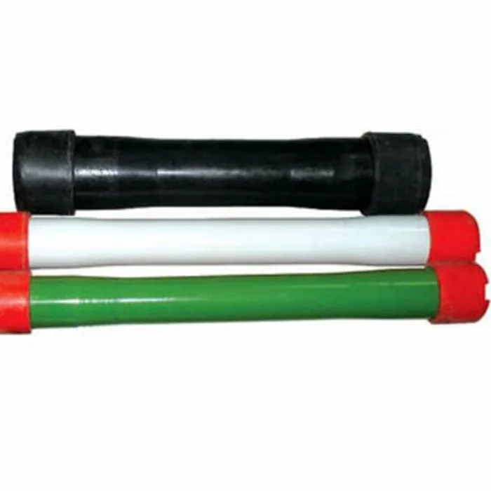
pup joint or upper nipple extensiom free sample
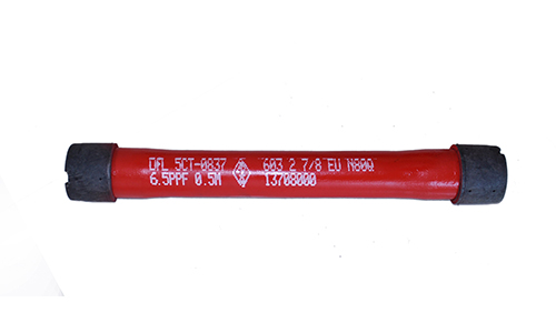
A pup joint is Casing, Pipe or Tubing shorter in length than a standard tubular string. This allows for the adjustment and installation of tools and various tubular components when placement downhole is critical for a specific project. A Spacer Pipe is another reference used to identify pup joints. Pup joint features consist of connections, lengths, weights and material grade.
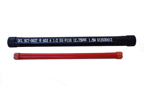
Crossover pup joints are manufactured from seamless mechanical tube. As with all Crossover products, each piece is marked with a distinctive job number and heat number that is fully traceable. A complete range of sizes (1" to 4.5"), weights (standard or heavy wall), and grades (J-55, N-80, L-80, and P-110) are commonly available from stock in 2", 3", 4", 6", 10", and 12" lengths. Lengths up to 20" are available upon request.
Manufactured according to API Spec 5CT using prime API monogrammed, seamless oil country tubing. Optional diameters, lengths, weights, and grades are available upon request.
Seamless pup joints with premium connections are available in API and exotic alloy grades. Premium ends are threaded by the manufacturer or authorized licensee.
Available with standard or special perforation spacings. Each joint has four rows of ⅜ inch holes drilled longitudinally along the tube. Optional patterns, hole size, and lengths furnished upon request.
Crossover, Inc. handles many types of API Couplings. As a rule, we stock enough of your common couplings which enable us to ship the same day if needed. We carry in stock J-55, L-80, N-80, and P-110. As for sizes, we carry 2 3/8”, 2 7/8” 3 ½”, 4 ½” tubing and some of the casing sizes up to 13 3/8”. Stock connections are EU 8 Rd., Nu 10 Rd., LTC, STC, and BTC. Our couplings are primarily of USA manufacture. If origin is not important, we can source other origins and sometimes beat the USA manufactured cost.
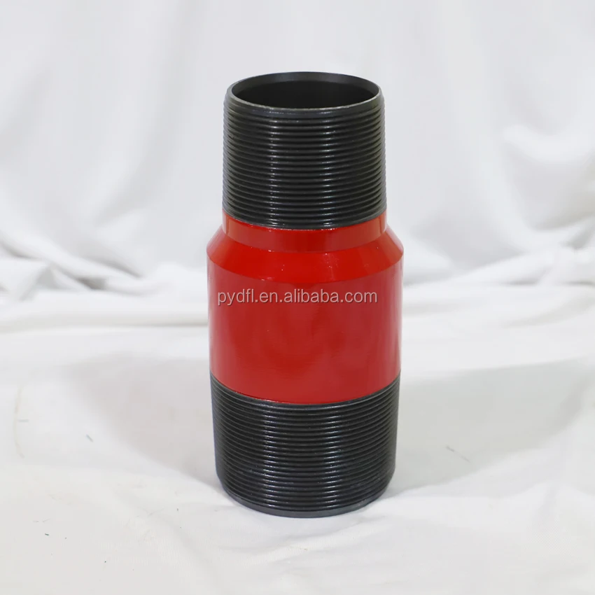
We manufacture a wide range of Crossover Couplings. Couplings are used to connect two sizes of pipes, or two different dissimilar threaded parts together. We offer special clearance couplings, special clearance couplings with bevels on both ends, and couplings with the API Seal Ring Modification.
Swages are generally Box x Pin with a transition on the outside diameter and the inside diameter of the swage to assure that there are no sharp corners to set up an area of stress risers. When stress risers occur, there is a chance that the part could fail due to the fact that the part would be prone to crack in these areas.
A blast joint is shorter in length than standard tubular joint. Built with a heavy wall pipe it is incorporated in the production string to facilitate production across any perforated interval and zone. Blast Joints are manufactured to the following specs connections, lengths, weights and material grade.
Crossover Blast Joints are heavy wall pin by box connectors used in tubing strings and are designed to minimize the effect of external erosive action caused by production fluids. Blast joints are located opposite the location of perforations in the production casing or just below the tubing hanger in sand frac designs. Crossover blast joints are manufactured from seamless mechanical tube in sizes ranging from 2 3/8” to 4 1/2” OD. Any length, grade of material, and threading is available at the customers request. Typical lengths are 10" and 20". Both API and Premium threads are available.
Crossover Flow Couplings are heavy wall box by box connectors used in tubing strings and are designed to minimize the effect of internal erosive action caused by production fluids. Flow couplings are located just above or below Landing Nipples, Safety Valves or Control Devices where turbulent flow problems are likely to occur. Crossover flow couplings are manufactured from seamless mechanical tube in sizes ranging from 2 3/8” to 4 1/2” OD. Any length, grade of material, and threading is available at the customers request. Typical lengths are 3" and 6". Both API and Premium threads are available.
Crossover Coarse Thread Tubing Safety Joint provides for emergency recovery of the major portion of the tubing string should it become necessary to abandon the equipment below. Precision left-hand threads facilitate the release of the joint by right-hand tubing rotation. Equipment requiring right-hand rotation should not be used below the Safety joint.
Crossover Straight-Pull/Shear-Out Safety Joint is used between packers in dual and triple completions and in selective completions using Hydrostatic Single-String Packers. It is also used when rotational releasing is not desired. When ran above the upper packer in a single-string completion, however, the shear value should be adjusted to compensate for any hydraulic conditions that exist when the string is landed, or that are created by well treating operations. They are available in keyed and non-keyed configurations.
Crossover Gas Anchor is an effective and simple design. It will increase oil and gas production, improve efficiency of the lift system, correct artificial lift problems caused by incomplete pump fillage due to gas interference and reduce operating cost.
Crossover can build these in any of the regular API Grades such as J-55, L-80, or P-110. These are usually only made going up or down one size in either direction such as ¾” to 1” or 1 ½” to 2”.
A saver sub falls under the drill string accessory tool category and a short pipe that is replaceable and expendable without a major investment. This accessory protects the Kelly or topdrive component threads and those components represent a significant capital cost and considerable downtime when replaced. Saver sub are manufactured to the following specs connections, lengths, weights and material grade.
A lift sub falls under the drill string accessory tool category and utilized to mobilize various tools during drilling or fishing operations. Lift Sub are manufactured to the following specs connections, lengths, weights and material grade.
A circulating sub falls under the downhole accessory tool category that regulates flow rates, especially drilling in slimhole wells or wellbore cleanout projects. Circulating sub is manufactured to the following specs connections, lengths, weights and material grade.
Crossover Drop Ball Circulating Subs are manufactured from AISI 4140/4145. The standard is pin by box. They are activated by dropping a chrome steel ball, which lands on a sleeve and as pressure increases, the pins in the sleeve are sheared. This causes the sleeve to move down and expose four ports in the side of the sub diverting the fluid flow.
A side-entry sub falls under the drilling tool accessory category to allow various drilling, fishing, wireline operations through drill pipe without interference from the rig"s top drive unit. Circulating sub is manufactured to the following specs connections, lengths, weights and material grade.
The style shown is built from one piece of 4145M bar stock and the excess material milled away and then threaded. There are also Lift Caps which are Cast Steel Castings and are threaded with the correct thread, but the rest of the plug is casts to create the bail.
Some customers request Lift Caps with Pad Eye for lifting. These are also made out 4145M and can be manufactured to fit any of several shackles. They can be built with either the pin or the box facing down.
These brushes are generally run on Rotary Shoulder Drill String to Brush the inside of Casing Down Hole. These brushes will remove rust, scale and other contaminates that build up on the inside diameter (ID) of the casing. Usually run in preparation of running a packer or some other piece of equipment that needs a fairly uniform ID to set.
Crossover Inside BOP Valves are manufactured from AISI 4145. Crossover"s one piece design is much more robust than the traditional two piece construction design. Crossover"s one piece design typically allows for standard connection OD"s and shorter overall length parts. This eliminates the service break which allows for quicker disassembly.
A washover pipe is Casing or Pipe shorter in length than a standard tubular string. Made of large-diameter pipe with a cutting surface at the tip, washover pipe is run in the well and then the cutting edge grinds the fish to a smooth surface and continues normal operations. Washover Pipe is manufactured to the following specs connections, lengths, weights and material grade.
Crossover rotary shoes are manufactured from specially tempered steel to provide the ultimate in toughness and durability. They are used to cut a clearance between the fish and the wall of the well bore. Each shoe is tailored to fit a particular downhole need and normally is run on the bottom of one or more joints of washover pipe. Shoe design is dictated by whether it cuts on the bottom, on the OD, on the ID, or any combination of these. When hole sizes permit, additional clearances can be cut using side ribs, thus providing greater circulation.
Pipe system involves various components, including pup joint nipple and are made from different materials. We offer wholesale pup joint nipple to create a smooth channel for the pipe systems in both commercial and residential areas.
The materials used depend on the type of fluids it will convey. One of the more commonly used types is PVC fittings. Features of the PVC pipe fittings that make an appropriate is the allowance for a smoother wall surface which decreases resistance to the flow. It is also lightweight and cost-effective.
On the other hand, copper fittings are corrosion-resistant. As such, they have a higher tolerance to external factors. That makes copper pipe fittings a good option to adopt for underground plumbing.
Apart from materials, there are also other components of the pipe fittings to note. P-traps prevent odor by retaining a small pool of water to stop sewer gases from entering the bathroom. Pipe caps cover the end of pipes to stop the fluid flow and protect pipe threads.
The usage of the pipes plays a crucial role in the materials suitable. For manufacturing, pipes will need to be able to withstand the fluids conveyed. We provide solutions from pipe bends to copper pipe compression fittings for any piping system required.

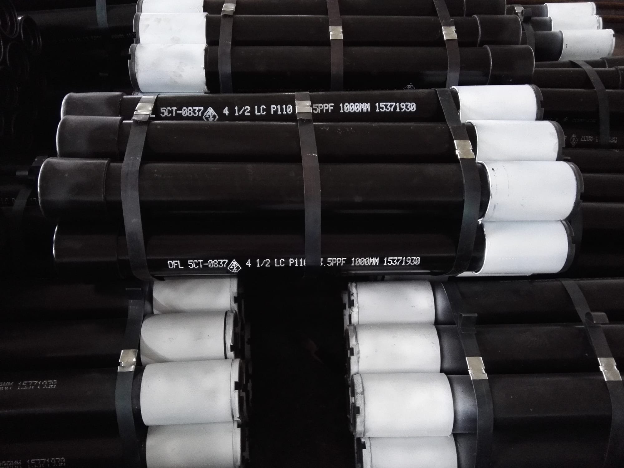
These J55, L80, N80Q & P110 pup joints are manufactured from seamless Grade J-55, L80 N80Q and P110 mechanical tubing. The API 5CT tubing pup joint is mainly used to adjust the height of the tubing strings. It is also used to adjust the depth of down-hole tools.
This website is using a security service to protect itself from online attacks. The action you just performed triggered the security solution. There are several actions that could trigger this block including submitting a certain word or phrase, a SQL command or malformed data.
This website is using a security service to protect itself from online attacks. The action you just performed triggered the security solution. There are several actions that could trigger this block including submitting a certain word or phrase, a SQL command or malformed data.
The RIG will be mobilized from XXX to XXX. The rig will be moored in approximately xxx’ water depth. A string of 36” x 1.5” and 1.0" wall structure pipe will be jetted to xxx’ TVD / MD (xxx’ BML). The shallow hazards survey indicates possible low risk shallow gas potential from the mudline to approx. xxx’ TVD (xxx’ BML) and negligible to moderate risk shallow water flow potential at xxx’ TVD / MD (xxx’ BML).
After jetting the 36” structure pipe to the desired depth, the Drill Ahead Tool (DAT) will be used to drill 26” hole to xxx’ TVD / MD (xxx’ BML) and 20” casing will be run and cemented. The shallow water flow study indicates only low to moderate potential for over-pressured sands through this interval. Should a shallow flow be encountered while drilling riserless, 16.0 ppg kill mud will be available on the rig to control any such flow. After running and cementing 20” casing, the subsea BOP stack and riser will be run and tested. Prior to drilling out of the 20” casing, the hole will be displaced with 10.0 ppg synthetic based mud. A LOT of 10.7 ppg is expected at the 20” casing shoe. LWD (GR/RES/APWD/DIR) will be utilized in this hole section.
A 17’’ x 20” hole will be drilled to xxx’ TVD / MD and 16” casing will be run and cemented. This casing string is being set at this depth based on pore pressure and frac gradient. The expected mud weight at casing point is 10.4 ppg and the expected LOT at the 16” casing shoe is 12.4 ppg EMW. LWD (GR/RES/APWD/DIR) will be utilized in this hole section.
A 14 1/2’’ x 17 1/2” hole will be drilled to xxx’ TVD / xxx’ MD. The KOP for the directional work is planned at 7300" TVD/MD. A major azimuth change while building hole angle will be accomplished in this section using rotary steerable tools. A full string of 13 5/8” casing will be set. The expected mud weight at casing point is 12.0 ppg and the expected LOT at the 13 5/8” casing shoe is 14.2 ppg EMW. LWD (GR/RES/APWD/DIR) will be utilized in this hole section.
Based on the formation evaluation results, either this hole section will be permanently abandoned and the cased hole temporarily abandon pending completion, or the entire well will be permanently abandoned.
DWOP exercises will be conducted with drilling contractor personnel, service company personnel, COMPANY drilling supervisors and engineering staff prior to spud.
The rig will be mobilized from XXX. The move is anticipated to take 8 hours. When rig reaches XXX, the rig will approach the location from the North. (Refer to FUGRO site survey for information on bottom conditions, hazards, etc.).
As the rig approaches the actual location, the AHV will begin placement of the 1st anchor. XXX will provide tools, equipment, crews for anchor handling operations, and contingency equipment.
While holding rig on station, the remaining anchors will be run per the mooring procedure and the placement confirmed by the surveyors on board. Once on location AHV will begin running anchors as per mooring procedures. Once the 4 primary anchors are run and pretension, the tug can be released.
Pretension anchor chains to Contractor’s specifications for the rig. The rig will then ballast to drilling draft, and storm tension the mooring system.
The COMPANY Drilling Supervisors, Logistics Coordinator and Drilling Superintendent will prepare an initial “Required Personnel and Equipment” load-out list.
Measure and inspect the 36” casing. Clean the 36” casing connectors (RL-4 RB). Vetco representative should inspect the connections for damage. Apply light oil to box and pin surfaces and re-install pin protectors.
Verify 36" casing and jetting assembly tallies to ensure bit is no more than 6-8" outside the casing shoe. Adjust BHA length by the use of drill pipe pup joints and/or by cutting the 36" beveled end to fit.
P/U joint with beveled end x Vetco RL-4RB pin and run through rotary. Clean threads and apply AP-5 grease or lead-free API modified casing dope. Do not use any use API or other metallic- base thread compound.
Run required joints to allow 280" of penetration BML with 12" of stick up with the gas/mud mat at the ML. Make up connection and torque to recommended optimum torque. (See detailed VETCO procedure in the specific casing program section) Clean threads and apply API modified casing dope.
Make up CADA on inner jetting assembly and land in wellhead housing. Confirm the tool is locked in the housing and the ports in the top of the tool are open.
Pull the two halves back to either side of the moon pool area so that they are positioned for sliding together. Secure the two halves with chains or tack weld to the deck.
Start pump at 200 gpm to keep bit nozzles from plugging when tagging mud line. Record string weight. Tag mud line and record depth. Record bull’s-eye angle and direction.
Reciprocate casing as required (30" - 40" stroke length recommended) to prevent packoffs inside casing, to reduce friction between the structural casing and jetted formation, and maintain jetting progress once resistance / soil friction begins increasing (recommend to be reciprocating by 100" BML at LATEST). Successful operations have reciprocated as often as every other 5" to avoid formation creep from sticking structural casing. Reciprocation and sweeps are key elements to a successful jetting operation. Past experience indicates that jetting to xxx"" to xxx" BML provides sufficient skin friction to support wellhead loads.
Record the following data on a basis: Time to jet 5", WOB, gpm, psi, comments, and notations on pipe reciprocation (when and how much the pipe was reciprocated) and the pumping of sweeps (volume and viscosity). Also note any overpull while working pipe.
Slack off weight and ensure casing is stable and remains straight. Record final bull"s eye level. Notify Drilling Superintendent if it is greater than 1.0o.
Pump 50 bbl (or slugging pit volume) hi-vis (FV > 100 sec) sweeps of seawater and prehydrated bentonite at each connection (more frequently if needed) and 50 bbl (or slugging pit volume) hi-vis pill at each half stand drilled.
Make a wiper trip to the structural casing shoe with seawater in the hole. Circulate hole clean and displace 150% hole volume with 13.5 ppg CaCl2 spotting mud. To prevent potential wellbore instability, DO NOT place freshwater mud in the hole.
Ensure MWD survey and bulls-eye indicates a wellbore angle of 1.0o or less. If 1.0o angle is exceeded, check the rig offset and consult with the Drilling Superintendent.
Post personnel to monitor water surface for gas bubbles and prepare to move rig into the current if gas bubble is present and in close proximity to the rig.
Utilize the blender to increase the mud weight from 12.0 to 14.0 ppg and circulate a minimum of two hole volumes. Circulate at max. rate during kill. Monitor ECD with the APWD readout.
Shut down pumping and monitor well for flow with ROV. If well is still flowing, continue mud weight increase to kill the flow. Once well is dead, options will be discussed with members of the extended drilling team.
If a water flow is encountered, attempt to determine relative severity of flow. If water flow is minimal, consideration will be made to continue drilling to the 20” casing point. If flow is severe, increasing the mud weight or a dynamic kill will be considered. In either case, contact the COMPANY drilling staff to discuss options.
In the event of encountering either shallow gas or shallow water flow, the cement loaded for the 20" casing is acceptable for and will be used for the 26" contingency.
Lost circulation could occur if high annular loading results in an EMW greater than fracture gradient. Monitor APWD to determine ECD. Control drill this section at <100 ft/hr using as high of flow rates as practicable. Close observation to return flow via ROV is the only way to qualitatively tell if partial or full losses happen to occur.
If hole conditions deteriorate, torque increases, or if fill is observed either on connections or a short trip, it may be necessary to increase the volume, frequency, and viscosity of the hole cleaning sweeps.
Make up WHRT to 20" WH joint (with nominal seat protector and sufficient inner cement stinger to protrude from WH extension joint). Lay out on pipe rack or catwalk.
NOTE: Make sure VETCO serviceman uses a VX protector on the wellhead in order to protect the metal-to-metal sealing area of the wellhead. Also check to make sure a VETCO VT/VX gasket is available on the rig should the VX sealing area become damaged.
Install 2 centralizers with 1 stop collar for each centralizer on each of the bottom 3 joints. Install 1 centralizer with 1 stop collar at mid-joint on each of the next 3 joints. A total of 9 centralizers are to be run.
Before making up WH joint, install a key-slot plate, bowl, and slips on top of the 20" casing. Pick up the 5 1/2" 21.90 ppf DP inner cementing string.
Pick up the 5 1/2" 38 ppf landing string and RIH. Lower the wellhead to the water and pump out all the air from the 20" x inner string annulus. Close the both vent valves on top of the running tool (vent valves should have double valves for redundancy).
Continue running the casing on drill pipe to the mud line, filling the drill pipe every 5 stands. See Figure No. 2 at the end of this section for running weights and tensile capacities.
Monitor 20" movement at the WH with the ROV. Ensure drill pipe movement at the rig floor is consistent with casing movement at the wellhead to avoid buckling the 20" casing.
Slowly slack off the weight of the casing string – monitor for settling with ROV. If settling is observed, hold with DP for 4 hours or until surface cement samples set (set surface samples in refrigerator to approximate seafloor temperature).
Adjust the heave compensator to support about 2,000–3,000 lbs more than running string, WHRT, and cementing stinger weight. Release WHRT per VETCO operations manual and on-site VETCO service technician. When the tool releases, the heave compensator will stroke closed lifting the tool free from the housing.
Hold pre-job safety meeting on handling and running procedures for BOP stack, LMRP, and marine riser with all parties involved. Adhere to weather limitations as per rig-specific operations manual supplement.
a) Install the methanol / glycol injection umbilical for the H-4 connector ROV quick stab. Stab umbilical into ROV port. Colored methanol / glycol will be pumped through the umbilical to flush connector cavity at ±7 day intervals. Glycol is preferable.
a) Record hook load every joint while running riser. Also record weights for the TDS/Traveling Block, riser running tool, tensioning ring (if not integral to telescopic joint), and diverter housing/upper flex joint. Send data to Drilling Engineer for review.
d) Pick up slip joint (closed) and landing joint and record buoyed weight of the BOPS and riser. Report weight of BOP and riser on daily drilling report. Notify office immediately if actual weight and estimated riser weight figures differ by more than 30 kips.
Test wellhead connector, shear rams, and casing to 250 / 3970 psi surface pressure while laying down the landing joint. Pressure must not decline by more than 10% in 30 minutes.
Note the % offset assumed for the minimum required tension. If this % offset is exceeded at any point, contact the office to obtain applicable top tension requirements for greater offsets.
Do not sacrifice hole maintenance for incremental reductions in overall time. Recent experience shows that shortcutting standard oilfield practices actually contributes to NPT.
20" - 25" for rat hole is sufficient below long strings of casing, and 5" is sufficient below the liners. This limits the length of oversized, open hole below casing shoes where cuttings can accumulate. It also prevents excessive cement slump that can detrimentally effect the shoe test upon drilling out that can be a problem given the recommended cement slurry densities vs. the planned section TD MWs.
Drill with a minimum of 120 rpm with the Baker Autotrack system. If possible increase to 150 – 180 rpm. Balance ECD with the higher RPM. Watch for vibrations at the higher RPM and backoff the rpm to remove excessive vibrations.
When circulating off bottom (hole conditions permitting) increase the rpm to ABOVE the on-bottom rpm for increased hole cleaning (ie at least 150-180 rpm). Watch for vibrations at the higher RPM and backoff the rpm to remove excessive vibrations.
When the bit is OFF BOTTOM, at the rig record the surface torque, rotating string weight, and pick up and slack off readings on every other connection. Baker will provide a predicted rotating torque plot off bottom. Plot the predicted vs actual on a graph (Y axis depth; x axis surface tension). Monitor hole cleaning using the chart. If the trend lines start diverging away from the predicted then hole cleaning problems are occurring.
When pumping a sweep pull the bit off bottom prior to the sweep exiting the bit. Ensure the drill string is at least 60 RPM while the sweep exits the bit. Increase the drill string rotation to a minimum of 120 RPM while pumping the maximum GPM while the sweep is moving up the annulus. Consider pumping piggyback sweeps by using a low vis then high vis sweep.
After circulating the hole clean, while POOH if a tight spot or swab is encountered, always first assume it is a cuttings bed problem (hole cleaning related). Steps for tight hole while tripping out:
If a tight spot is encountered, DO NOT TURN ON THE PUMPS OR ROTATE AT THE TIGHT SPOT. TIH to clear the BHA from the tight spot. Circulate at max GPM and max rpm for 30 minutes. Again POOH slow without the pumps or rotation. If the tight spot is gone, it was a cuttings bed problem and we just moved it up the hole. Stop and circulate at max GPM with max rpm at least bottoms up until the hole is clean. If the tight spot is still there, then carefully backream as required.
Pumping out of the hole without drill pipe rotation is generally unacceptable and leads to backreaming conditions which often leads to packoffs and lost circulation. Pumping out without rotation can cause a cuttings bed above the BHA. If pumping is needed consider TIH a few stands and maximize GPM and rpm while pumping. Circulate clean then POOH without the pumps or rotation.
Inspect NAF transfer hoses, clean out the mud pits. If more than 10-15 bbl of water remains in the pits, add 1-2 sacks of calcium chloride, and put 40-50 mesh screens on shale shakers for initial circulation of thick NAF.
Pump NAF at 1200 gpm. Reduce rate if pressures are increasing or if returns run over the shakers. Do not stop pumping once the displacement has commenced unless absolutely necessary.
When clean NAF returns are seen, record strokes, start shakers, and route NAF to pits. Calculate how much water was left in the hole from stroke count.
Begin remedial treatments as required. Add emulsifier and wetting agents at the shakers or at the suction (or both locations in case of severe contamination) as needed.
Before drilling the shoe, break circulation and circulate prior to taking slow pump rates. Check and record choke and kill line friction pressures. Perform power choke drill.
Once a LOT is obtained and drilling commences, pump 100 bbl x 200 vis supersweeps as necessary but at least prior to connections for 1st 300" of 17 ½" x 20" hole drilled.
Pump 100 bbl (or slugging pit volume) viscous and/or weighted NAF "supersweeps" every stand for the first 300" and at least every 2 stands thereafter.
At section TD, perform wiper trip only if warranted by hole conditions. Pump hi-vis weighted sweep and circulate hole clean with a minimum of 2 bottoms up.
Hold pre-job safety meeting on running casing with all parties involved. Verify the running string design provides adequate capacity for the planned use.
If casing length is greater than riser length, have casing x running string crossover(s) on rig floor. Also have full-opening safety valve for running string in open position and ready to stab, if needed.
Protech/Centerform composite centralizers will be Installed on the 3 joints to run as the shoe track and the 2 joints immediately above. 2 backup joints will also have the centralizers.
Apply light coat of AP-5 grease or lead-free API-modified thread compound to each connection, but do not use API or other metallic-base thread compound.
After landing in the casing hanger, makeup the ATC Cement head on drillpipe and begin pumping to close the diverter. The 2 1/4" ball will be on the seat in the Diverter Sub, pressure up to 1000 psi and hold same for 2 to 3 minutes. Continue to increase pump pressure until the ball yields the seat at 2200 to 2600 psi.
Approximately 5-10 barrels prior before the bottom DP dart reaching the ATC Diverter Sub slow the pump rate to 5 BPM. The pressure required to yield the seat in the Diverter with the pump down plug should range from 500-800 psi above the circulating rate.
When the Bottom ATC Casing Wiper Plug reaches the ATC WPI, 700-1000 psi pressure should be applied to activate the Plug Circulating system. The plug will shift to the open position and displacement can be resumed at normal pumping rates.
Approximately 5-10 barrels prior before the Top DP dart reaching the ATC Diverter Sub slow the pump rate to 5 BPM. The pressure required to yield the seat in the Diverter with the pump down plug should range from 500-800 psi above the circulating rate.
Continue with displacement. Approximately 5-10 barrels prior to the calculated Top Plug displacement to the WPI, slow the pump rate to 3 bbls per minute.
Before drilling the shoe, break circulation and circulate prior to taking slow pump rates. Check and record choke and kill line friction pressures. Perform power choke drill.
Once a LOT is obtained and drilling commences, pump 100 bbl x 200 vis supersweeps as necessary but at least prior to connections for 1st 300" of 14 1/2" x 17" hole drilled.
Use 6 1/4" or 6" mud pump liners and sufficiently large mesh shaker screens to ensure ability to sweep the hole and handle the increased amount of cuttings at the surface.
Pump 100 bbl (or slugging pit volume) viscous and/or weighted NAF "supersweeps" every stand for the first 300" and at least every 2 stands thereafter.
Drill hole to fit casing tally with 20" - 25" of rat hole below casing shoe. Do not drill more than 50" beyond APD shoe depth, 9600" TVD / 9692" MD RKB.
At section TD, perform wiper trip only if warranted by hole conditions. Pump hi-vis weighted sweep and circulate hole clean with a minimum of 2 bottoms up.
Ream undergauge portion of the hole to eliminate excessive rat hole. This will leave approx. 3" of undergauge hole due to bit-NBR spacing. If casing is to be run without logging or another trip for mud conditioning, condition/thin mud properties for casing running.
Hold pre-job safety meeting on running casing with all parties involved. Verify the running string design provides adequate capacity for the planned use.
If casing length is greater than riser length, have casing x running string crossover(s) on rig floor. Also have full-openg safety valve for running string in open position and ready to stab, if needed.
Protech/Centerform composite centralizers will be Installed on the 3 joints to run as the shoe track and the 2 joints immediately above. 2 joints to be run below the casing hanger will also have the centralizers installed. 2 backup joints will also have the centralizers.
After landing in the casing hanger, makeup the ATC Cement head on drillpipe and begin pumping to close the diverter. The 2 1/4" ball will be on the seat in the Diverter Sub, pressure up to 1000 psi and hold same for 2 to 3 minutes. Continue to increase pump pressure until the ball yields the seat at 2200 to 2600 psi.
Approximately 5-10 barrels prior before the bottom DP dart reaching the ATC Diverter Sub slow the pump rate to 5 BPM. The pressure required to yield the seat in the Diverter with the pump down plug should range from 500-800 psi above the circulating rate.
When the Bottom ATC Casing Wiper Plug reaches the ATC WPI, 700-1000 psi pressure should be applied to activate the Plug Circulating system. The plug will shift to the open position and displacement can be resumed at normal pumping rates.
Approximately 5-10 barrels prior before the Top DP dart reaching the ATC Diverter Sub slow the pump rate to 5 BPM. The pressure required to yield the seat in the Diverter with the pump down plug should range from 500-800 psi above the circulating rate.
Continue with displacement. Approximately 5-10 barrels prior to the calculated Top Plug displacement to the WPI, slow the pump rate to 3 bbls per minute.
Flow rate: 800 - 1025 gpm. Boost riser. Sands may be highly unconsolidated. Do not exceed the specified flow rates when close to sand reservoirs. Do not perform extended circulation with bit across sands (circulate bottoms up, then pick up above sand to complete circulation).
Pump 50 bbl viscous and/or weighted NAF sweeps (FV > 100 sec) every stand for the first 100m and at least every 2 stands thereafter. Occasional sweeps should be pumped to check for cuttings buildup in the hole.
Take MWD directional survey readings every stand. Ensure MWD is set to operate in the volume range to correspond to the programmed bit hydraulics requirements for this hole section.
Ream undergauge portion of the hole to eliminate excessive rat hole. This will leave approx. 3" of undergauge hole due to bit-NBR spacing.Condition/thin mud properties for casing running.
POOH SLM and rabbit the DP using a 2 5/8” or greater OD drill pipe drift with +-120’ of wire attached and recover drift. Lay out any joints of drill pipe that do not drift. Compare to previous tally.
Have Weatherford service personnel on location. Inventory all liner equipment and tools prior to running. Double-check all lengths, OD’s, and ID’s, with Weatherford Stab Up Drawing. Verify that all dimensions are compatible with the casing and well bore.
After logging, depending on logging duration and hole conditions, a complete wiper trip to TD (may need to stage into the hole after a long logging job) should be performed.
Pump hi-vis weighted sweep and circulate hole clean with a minimum of 2 bottoms up. Condition the mud – DO NOT POOH until mud properties are within required specifications for running casing. Mud rheology may be thinned to below program specs prior to running casing.
If casing length is greater than riser length, have casing x running string crossover(s) on rig floor. Also have full-opENIng safety valve for running string in open position and ready to stab, if needed.
Make up and stand back the liner hanger/running tool and cementing plug assembly per instructions of cementing and Weatherford service personnel and their respective Field Service Manuals.
a) Protech/Centerform composite centralizers will be Installed on the 3 joints to run as the shoe track and the 2 joints immediately above. 2 backup joints will also have the centralizers.
g) If necessary, place one pup joint with a radioactive tag approximately 300" above each reservoir to flag the sands. Pup joint placement should specified in the program addendum.
Make up liner hanger assembly. LEAVING ROTARY SLIPS SET ON LINER JOINT, pick up approximately 3 feet to verify that the setting tool and all connections are properly torqued up. Once this has been done, pull slips, slack off until PBR sleeve is accessible from the rig floor. Fill the Floating Junk Bonnet with clean water. DO NOT SET SLIPS ON SETTING SLEEVE / PBR. SET DRILL PIPE SLIPS ON SETTING TOOL LIFT SUB. Make up stand of drill pipe to the liner hanger assembly running tool and lower assembly into well. Record liner weight.
When the 11 7/8” guide shoe reaches the 13 5/8” casing shoe, screw the top drive into the last stand before going out to open hole and get slow pump rates at 15 – 25 – 35 spm through the ATC Diverter Sub. After recording these pressures continue running the liner. Also record liner pick up, slack off, and static weights.
If Liner rotation is anticipated being required in open hole, calculate maximum drill down torque. Liner thread maximum make-up torque, plus rotating torque established at the casing shoe on last trip out of the hole (Step 15 above) minus 20% safety factor = maximum drill down torque. (Rotate slowly at the shoe prior to entering open hole and record minimum torque required to maintain sustained rotation. This torque to be used as reference.
When the liner is one stand off bottom, screw the Top Drive in and start pumping slowly to close the ATC Diverter Sub. Keep the pipe moving down hole during this operation. The 1 3/4" ball will be on the seat so pressure up to 600 psi slowly and hold the same for 2 or 3 minutes. Then continue to increase the pump pressure until the ball yields the seat (1500-1800 psi). Note: You will be TIH very slowly when you perform these steps.
After blowing the ball through the seat go back to circulating at 15 spm and record the pump pressure once the returns have stabilized (Do not exceed 800 psi during this operations – the nominal setting pressure of the WCS liner hanger is 1600 psi). The 1 3/4" ball will drop into the ATC Liner Plug System and rest on top of the 3 1/2” ball.
Calculate amount of slack off required to transfer all the liner weight plus 30,000 lbs. of drill pipe weight onto the liner hanger. Space out drill string to put the Cementing Head a minimum of that distance from the rig floor once hanger is hung off and weight slacked off.
After reaching total depth with the liner, pick up ATC Cement Head and make up same. Start circulating at 30 spm, and record the pump pressure once the returns have stabilized.
Establish pick up and slack off weights. Reciprocate liner while circulating and conditioning mud / hole. (If well conditions permit, and operator has given approval, it is recommended that the pipe be reciprocated during the mud / hole conditioning. Ensure that the reciprocation stroke is not long enough to uncover any formation that must be isolated. This will ensure that inadvertently sticking pipe will not leave that formation uncovered. (It is imperative that the driller understand that the reciprocation stroke be a slow steady movement to prevent harmful pressure surges.)
After blowing the ball through the seat the 2 3/8" ball will drop to the ATC Liner Plug System where the ball will land in a yieldable seat. At that time the WCS rep will pressure up in stages to set the hanger (hydraulic hanger set pressure = 1,600 psi). Hold the pressure while the WCS rep works the liner to check and determine if the Hydraulic Hanger is set.
Shut down circulation. With 10-20,000 lb. of drill string weight down on liner hanger, rotate 6-8 torque free turns to the right to release setting tool from the liner. Pick up stretch in pipe plus 5"-10" to see liner weight loss ensuring that setting tool is released from the liner. Note: Ensure that setting tool is not picked up high enough to remove packer actuator sub from the PBR extension. (Double check pick up on slick joint and Floating Junk Bonnet polish nipple)
Set 30,000 lb. of drill string weight back down on liner hanger, to prevent pump out forces of cement job from inadvertently pumping the setting tool out of the liner. Prepare to cement. (Note: Slack off weight will vary from job to job. The Weatherford serviceman will figure his pump out forces on setting tool and set down sufficient weight to overcome those pump out forces)
Circulate and condition the drilling fluid for the upcoming cement job. Recommend not circulating above 30 strokes per minute until the thick mud is above the liner assembly. Circulate bottoms up (minimum 2 x bottoms up from TD to liner top). Boost riser.
Displacement will be with mud. NOTE: IF SYNTHETIC DRILLING FLUIDS ARE BEING USED COMPRESSIBILITY FACTORS, IF APPLICABLE, MUST BE ENTERED INTO DISPLACEMENT FIGURES. CONSULT WITH OPERATOR RIG SUPERINTENDENT AND /OR MUD ENGINEER TO OBTAIN THIS INFORMATION.
Approximately 5 barrels prior to the drillpipe dart reaching the ATC Diverter Sub slow the pump rate to 5 bpm . The pressure required to yield the seat with the drillpipe dart should range from 1500 - 2000 psi (above the circulating pressure). After yielding the seat the drillpipe dart will latch the liner wiper plug. The pressure required to release the liner wiper plug will range from 1500 - 2000 psi (above the circulating pressure). Record pressure required to shear the plug. Continue with the displacement.
When the ATC Liner Wiper Plug reaches the WPI, 700 to 1000 psi (above the circulating pressure) should be applied to activate the WPI system. Resume the displacement making appropriate corrections to the total liner displacement if necessary. An additional 150 psi circulating pressure may be seen during this final displacement.
Set down minimum of 40000 lbs. (at liner top) to shear pins and energize the TSP packer (The packer actuator sub has rotational capability. Rotate drill string slowly to the right to change friction points and work weight down to the packer. Up to 100000 lbs. can be used to set packer if necessary.
Close rams, and put a quick test on liner top packer (800 – 1,000 psi). Hold test no longer than 3- 5 minutes if cement was calculated to reach up into lap of liner. (NOTE: Verify test procedures with Operator"s rig superintendent. Some operators prefer to reverse out cement prior to putting a test on Liner Top Packer.)
Pick up setting string leaving the end of the setting tool right at the liner top Begin reversing out slowly. Once returns are obtained, pick up slowly until the end of the running tool is approximately 5 feet above the liner top. Increase pump rate and continue to pick up slowly until the end of the running tool is 10-15’ above the liner top. Once sufficient fluid has been reversed out to ensure that all excess cement (Calculated Volume) is out of annulus and either at surface or at least 2,000’ from the end of the setting tool (inside drill pipe), slow pump rate to 1-2 barrels per minute. Slowly slack off setting string inserting the end of slick stinger back into the end of the PBR tie- back extension at least 5-7 ft. Continue circulating for 3-5 minutes and then slowly pick up leaving the slick stinger 5-10 ft above the liner top. Increase pump to desired rate and complete reversing out. Reverse out two drill pipe volumes or until no cement returns are observed. Limit circulating pressure to psi while reversing out to prevent overloading the liner hanger. PRIOR TO JOB VERIFY WITH OPERATOR’S HOUSTON OFFICE THE INTENT TO REVERSE OUT EXCESS CEMENT. VERIFY WITH WEATHERFORD SERVICEMAN LIMITING CIRCULATION PRESSURES.
If liner top did not test (if test was performed), and/or attempts to reverse out results in lost returns and/or pressure loss, or, if TSP packer was not set, DO NOT REVERSE OUT CEMENT AT LINER TOP. PULL 5-10 STANDS THEN REVERSE OUT.
MONITOR REMAINING CEMENT PUMPING TIME AS JOB PROGRESSES. IF LESS THAN 1 HOUR OF CEMENT PUMPING TIME REMAINS (INCLUDE ANTICIPATED REVERSE OUT TIME) WHEN LINER WIPER PLUG BUMPS AND PACKER IS SET, POOH WITHOUT REVERSING OUT CEMENT.
Pick up and RIH with jet sub, WBRT, and test-type 9 5/8" wear bushing. Wash WH thoroughly with jet sub and jet nozzle joint. Install wear bushing. If seawater was used to displace cement: Circulate out NAF mud from the upper wellhead, BOPS, riser, and choke, kill and booster lines with seawater.
Flow rate: 550 - 650 gpm. Boost riser. Sands may be highly unconsolidated. Do not exceed the specified flow rates when close to sand reservoirs. Do not perform extended circulation with bit across sands (circulate bottoms up, then pick up above sand to complete circulation).
Pump 50 bbl viscous and/or weighted NAF sweeps (FV > 100 sec) every stand for the first 100m and at least every 2 stands thereafter. Occasional sweeps should be pumped to check for cuttings buildup in the hole.
Take MWD directional survey readings every stand. Ensure MWD is set to operate in the volume range to correspond to the programmed bit hydraulics requirements for this hole section.
At section TD, perform wiper trip only if warranted by hole conditions. Pump hi-vis weighted sweep and circulate hole clean with a minimum of 2 bottoms up.
POOH SLM and rabbit the DP using a 2 5/8” or greater OD drill pipe drift with +-120’ of wire attached and recover drift. Lay out any joints of drill pipe that do not drift. Compare to previous tally.
Have Weatherford service personnel on location. Inventory all liner equipment and tools prior to running. Double-check all lengths, OD’s, and ID’s, with Weatherford Stab Up Drawing. Verify that all dimensions are compatible with the casing and well bore.
After logging, depending on logging duration and hole conditions, a complete wiper trip to TD (may need to stage into the hole after a long logging job) should be performed.
Pump hi-vis weighted sweep and circulate hole clean with a minimum of 2 bottoms up. Condition the mud – DO NOT POOH until mud properties are within required specifications for running casing. Mud rheology may be thinned to below program specs prior to running casing.
If casing length is greater than riser length, have casing x running string crossover(s) on rig floor. Also have full-opCOMPANYng safety valve for running string in open position and ready to stab, if needed.
Make up and stand back the liner hanger/running tool and cementing plug assembly per instructions of cementing and Weatherford service personnel and their respective Field Service Manuals.
Protech/Centerform composite centralizers will be Installed on each joint on each joint of casing at an interval of 1 per joint from the shoe track to 500" above the top of Galt 70 target.
Place one pup joint with a radioactive tag approximately 300" above each reservoir to flag the sands. Pup joint placement should specified in the program addendum.
Make up liner hanger assembly. LEAVING ROTARY SLIPS SET ON LINER JOINT, pick up approximately 3 feet to verify that the setting tool and all connections are properly torqued up. Once this has been done, pull slips, slack off until PBR sleeve is accessible from the rig floor. Fill the Floating Junk Bonnet with clean water. DO NOT SET SLIPS ON SETTING SLEEVE / PBR. SET DRILL PIPE SLIPS ON SETTING TOOL LIFT SUB. Make up stand of drill pipe to the liner hanger assembly running tool and lower assembly into well. Record liner weight.
When the9 7/8” guide shoe reaches the 11 7/8” casing shoe, screw the top drive into the last stand before going out to open hole and get slow pump rates at 15 – 25 – 35 spm through the ATC Diverter Sub. After recording these pressures continue running the liner. Also record liner pick up, slack off, and static weights.
If Liner rotation is anticipated being required in open hole, calculate maximum drill down torque. Liner thread maximum make-up torque, plus rotating torque established at the casing shoe on last trip out of the hole (Step 15 above) minus 20% safety factor = maximum drill down torque. (Rotate slowly at the shoe prior to entering open hole and record minimum torque required to maintain sustained rotation. This torque to be used as reference.
When the liner is one stand off bottom, screw the Top Drive in and start pumping slowly to close the ATC Diverter Sub. Keep the pipe moving down hole during this operation. The 1 3/4" ball will be on the seat so pressure up to 600 psi slowly and hold the same for 2 or 3 minutes. Then continue to increase the pump pressure until the ball yields the seat (1500-1800 psi). Note: You will be TIH very slowly when you perform these steps.
After blowing the ball through the seat go back to circulating at 15 spm and record the pump pressure once the returns have stabilized (Do not exceed 800 psi during this operations – the nominal setting pressure of the WCS liner hanger is 1600 psi). The 1 3/4" ball will drop into the ATC Liner Plug System and rest on top of the 3 1/2” ball.
Calculate amount of slack off required to transfer all the liner weight plus 30,000 lbs. of drill pipe weight onto the liner hanger. Space out drill string to put the Cementing Head a minimum of that distance from the rig floor once hanger is hung off and weight slacked off.
After reaching total depth with the liner, pick up ATC Cement Head and make up same. Start circulating at 30 spm, and record the pump pressure once the returns have stabilized.
Establish pick up and slack off weights. Reciprocate liner while circulating and conditioning mud / hole. (If well conditions permit, and operator has given approval, it is recommended that the pipe be reciprocated during the mud / hole conditioning. Ensure that the reciprocation stroke is not long enough to uncover any formation that must be isolated. This will ensure that inadvertently sticking pipe will not leave that formation uncovered. (It is imperative that the driller understand that the reciprocation stroke be a slow steady movement to prevent harmful pressure surges.)
After blowing the ball through the seat the 2 3/8" ball will drop to the ATC Liner Plug System where the ball will land in a yieldable seat. At that time the WCS rep will pressure up in stages to set the hanger (hydraulic hanger set pressure = 1,600 psi). Hold the pressure while the WCS rep works the liner to check and determine if the Hydraulic Hanger is set.
Shut down circulation. With 10-20,000 lb. of drill string weight down on liner hanger, rotate 6-8 torque free turns to the right to release setting tool from the liner. Pick up stretch in pipe plus 5"-10" to see liner weight loss ensuring that setting tool is released from the liner. Note: Ensure that setting tool is not picked up high enough to remove packer actuator sub from the PBR extension. (Double check pick up on slick joint and Floating Junk Bonnet polish nipple)
Set 30,000 lb. of drill string weight back down on liner hanger, to prevent pump out forces of cement job from inadvertently pumping the setting tool out of the liner. Prepare to cement. (Note: Slack off weight will vary from job to job. The Weatherford serviceman will figure his pump out forces on setting tool and set down sufficient weight to overcome those pump out forces)
Circulate and condition the drilling fluid for the upcoming cement job. Recommend not circulating above 30 strokes per minute until the thick mud is above the liner assembly. Circulate bottoms up (minimum 2 x bottoms up from TD to liner top). Boost riser.
Displacement will be with mud. NOTE: IF SYNTHETIC DRILLING FLUIDS ARE BEING USED COMPRESSIBILITY FACTORS, IF APPLICABLE, MUST BE ENTERED INTO DISPLACEMENT FIGURES. CONSULT WITH OPERATOR RIG SUPERINTENDENT AND /OR MUD ENGINEER TO OBTAIN THIS INFORMATION.
Approximately 5 barrels prior to the drillpipe dart reaching the ATC Diverter Sub slow the pump rate to 5 bpm . The pressure required to yield the seat with the drillpipe dart should range from 1500 - 2000 psi (above the circulating pressure). After yielding the seat the drillpipe dart will latch the liner wiper plug. The pressure required to release the liner wiper plug will range from 1500 - 2000 psi (above the circulating pressure). Record pressure required to shear the plug. Continue with the displacement.
When the ATC Liner Wiper Plug reaches the WPI, 700 to 1000 psi (above the circulating pressure) should be applied to activate the WPI system. Resume the displacement making appropriate corrections to the total liner displacement if necessary. An additional 150 psi circulating pressure may be seen during this final displacement.
Set down minimum of 40000 lbs. (at liner top) to shear pins and energize the TSP packer (The packer actuator sub has rotational capability. Rotate drill string slowly to the right to change friction points and work weight down to the packer. Up to 100000 lbs. can be used to set packer if necessary.
Close rams, and put a quick test on liner top packer (800 – 1,000 psi). Hold test no longer than 3- 5 minutes if cement was calculated to reach up into lap of liner. (NOTE: Verify test procedures with Operator"s rig superintendent. Some operators prefer to reverse out cement prior to putting a test on Liner Top Packer.)
Pick up setting string leaving the end of the setting tool right at the liner top Begin reversing out slowly. Once returns are obtained, pick up slowly until the end of the running tool is approximately 5 feet above the liner top. Increase pump rate and continue to pick up slowly until the end of the running tool is 10-15’ above the liner top. Once sufficient fluid has been reversed out to ensure that all excess cement (Calculated Volume) is out of annulus and either at surface or at least 2,000’ from the end of the setting tool (inside drill pipe), slow pump rate to 1-2 barrels per minute. Slowly slack off setting string inserting the end of slick stinger back into the end of the PBR tie- back extension at least 5-7 ft. Continue circulating for 3-5 minutes and then slowly pick up leaving the slick stinger 5-10 ft above the liner top. Increase pump to desired rate and complete reversing out. Reverse out two drill pipe volumes or until no cement returns are observed. Limit circulating pressure to psi while reversing out to prevent overloading the liner hanger. PRIOR TO JOB VERIFY WITH OPERATOR’S HOUSTON OFFICE THE INTENT TO REVERSE OUT EXCESS CEMENT. VERIFY WITH WEATHERFORD SERVICEMAN LIMITING CIRCULATION PRESSURES.
If liner top did not test (if test was performed), and/or attempts to reverse out results in lost returns and/or pressure loss, or, if TSP packer was not set, DO NOT REVERSE OUT CEMENT AT LINER TOP. PULL 5-10 STANDS THEN REVERSE OUT.
MONITOR REMAINING CEMENT PUMPING TIME AS JOB PROGRESSES. IF LESS THAN 1 HOUR OF CEMENT PUMPING TIME REMAINS (INCLUDE ANTICIPATED REVERSE OUT TIME) WHEN LINER WIPER PLUG BUMPS AND PACKER IS SET, POOH WITHOUT REVERSING OUT CEMENT.
Flow rate: 650 - 800 gpm. Boost riser. Do not exceed the specified flow rates when close to sand reservoirs. Do not perform extended circulation with bit across sands (circulate bottoms up, then pick up above sand to complete circulation).
Pump 50 bbl viscous and/or weighted NAF sweeps (FV > 100 sec) every stand for the first 100m and at least every 2 stands thereafter. Occasional sweeps should be pumped to check for cuttings buildup in the hole.
Take MWD directional survey readings every stand. Ensure MWD is set to operate in the volume range to correspond to the programmed bit hydraulics requirements for this hole section.


 8613371530291