
arduino rotary table free sample

The stepper motor will have to be sized for your application. I used a small 3 rotary table and dont plan on using it for anything other than indexing so a high torque NEMA17 did the job. If youre working with a larger rotary table or want to be able to use it as a 4th axis in the mill you will want at least a NEMA23 size motor. You will have to reach out to the forum for help with selection.
Youll have to install the Arduino software (IDE) on your computer. Spark Fun has a good step by step tutorial for completing the install. https://learn.sparkfun.com/tutorials/installing-arduino-ide

I used a scrap riser to mill a custom knob with 17 flutes as an example, because most traditional manual rotary tables and dividing heads struggle with dividing prime numbers.
I needed two large holes in plates, 46mm and 40mm. I mounted the plates on the rotary table, set the indexer to continuous run and slowly lowered the cutting bit. This saved me from having to buy 2 different size hole saws that I might never use again.

CNCR turns a stepper motor controlled rotary table into a CNC controlled device. It makes it easy to accurately set the position, rotate an index step back and forth, move between two positions or run at a constant speed. An automated lock signal can lock the rotary table when it is not moving. Place the rotary table on the cross slide of a lathe and you can change tools by pressing a button.
CNCR is optimized to run on a small 7" touch screen. The supported controller is GRBL version 1.1 (or compatible grblHAL, grbl_ESP32), a free open source controller based on affordable Arduino hardware. The controller can be connected by USB, Bluetooth or a (wireless) network. If you ever wanted to CNC your rotary table, this is the easy and affordable way to do it.

I"ve actually used Arduino"s for a number of projects over the last few years (and PIC"s, but that"s another story) but never used stepper motors, so I"m keen to play with this and see what it will do.
Garth, if you download from the DM link you will find three versions of the software in the zip file. The latest (I believe) is ver 2.3. If you open the sketch in the Arduino IDE the first line gives you the version number in confirmation.
Hi i wonder if any one can help i have tried two Arduino Uno boards and two different DF Robot keypads and get the same result that the up and down left keypads go through the menu but pressing select makes no difference they just show the menus .I have downloaded the software on two different computers and get the same result.

After writing the "conventional" Rotary Table Control program below (final version of the Arduino_Rotary_Table_Control_2019_Rev7 series), I decided to write a completely new program which would enable stepper motor control with acceleration and deceleration, as well as a number of additional features. For a link to this program, as well as additional related information, see this link:
[3-35-2019] Beeper Test programThis is a simple Arduino sketch which can be used to test whether a piezo beeper is working, and also to find the loudest (or otherwise most desirable) tone.
The code changes were made so that when stepper motor and rotary table parameters are entered into the program, calculations will be made in two ways:
The determination of the required number of steps to move is in all cases based on the theoretical steps, which are then converted to actual steps. This method provides the best approximation (typically with an error less than 0.01%), and enables the easy use of gear and table ratios which do not divide exactly into 360.

In this tutorial we will learn how rotary encoder works and how to use it with Arduino. You can watch the following video or read the written tutorial below.
A rotary encoder is a type of position sensor which is used for determining the angular position of a rotating shaft. It generates an electrical signal, either analog or digital, according to the rotational movement.
There are many different types of rotary encoders which are classified by either Output Signal or Sensing Technology. The particular rotary encoder that we will use in this tutorial is an incremental rotary encoder and it’s the simplest position sensor to measure rotation.
Let’s make a practical example of it using the Arduino. The particular module that I will use for this example comes on a breakout board and it has five pins. The first pin is the output A, the second pin is the output B, the third pin is the Button pin and of course the other two pins are the VCC and the GND pin.

Arduino based IR remote control code checker. ... Novice - experience. Working on downsizing the photos so they can be added. Find and display hex code for remotes to use the code in Arduino sketches.
For makers who are interested in electronics and coding for arduino, this is the code for Plant watering automation. The code is specifically made to be a timer and to set the temperature and humidity as well. Works with the ESP 8266 electronic...
800°C - OLED SSD 1306 128x32 - module - 4 screws M3 x 10 up to M3 x 20 will work The files of this thing include the Arduino code I used; basically a copy pasted merge of the library examples from Adafruit, which come along when installing the...
800°C OLED SSD 1306 128x32 - module 4 screws M3 x 10 up to M3 x 20 will work The files of this thing include the Arduino code I used; basically a copy pasted merge of the library examples from Adafruit, which come along when installing the libraries...
It is Arduino powered Morse Code Forwarder.The whole thing is 90 mm in width, 60mm in depth, and 51mm in height.You will need these parts: 1x Arduino Nano1x 400pin breadboard2x 5mm LED (one green, one red)2x resistors (don´t know, which I...
I ask 2 things of anyone who uses this: Give credit when possible to those who help you Improve and share code to better the experience for everyone Updated code an instructions:http://blog.mkme.org/index.php/arduino-sainsmart-4wd-robot/...
a spool holder bar that stores a weight bar inside (arduino based) shows live display of remaining material in weight or length, metric or imperial. auto reduces the spool"s weight, stores 6 common spool brands.
This is a fancy table, containing all letters of the Morse code, my friends and I have to learn to pass the German amateur radio licence. You can print it, or, as we did it. engrave it inside a piece of wood with a laser. ...I also included the original...
This thing is knob for rotary switch for arduino projects **Please, If you download my model - **click on Like button**. And if you found some problem let me know in comment section please....
i have also attached the arduino code i used to run the tank via bluetooth. the android app i used is Arduino_Control_Car. i used the wiring diagram form here for the motors...
... and less tilted. Changed arms for 5mm NeoPixels. Included small amp for louder beep and changed the knob a bit. Arduino code is included as is. On the back I made the speaker part a bit thicker and the hole for the charging port a bit larger....
For the entire project on which this is based, please visithttp://www.inmoov.fr/ Arduino FSR code This is not the best place to post this but in order to make it easy to find (A lot of InMoov discussions are taking place on this platform) I also post...
A good video to show how to wire everything up can be found here.. https://www.youtube.com/watch?v=8Kuf-MG-nYY&list=LL&index=28 The arduino code uploaded can be edited to change colors/patterns
I don"t advise to take the 5V from the ARDUINO for the HR LEDs and supply the Arduino with its small 7,5 to 9V power supply, especially if you put 3 to 4 Red Eyes boxes !!!
... and an arduino, you can feed your fish for up to 10 days while you"re out on vacation. Get the code for it Here! Unzip into your Arduino folder, and in the arduino IDE you can find the sketch under Sketches → RobotGeekSketches → Demos → FishFeeder
If wanted, a basic example of the Arduino code can be found here. If the countersinks on the face are a bit small due to elephants foot or bad supports, then heat-setting the washers that come with the WH148 units provides a really nice and...
... led lights. ... The Arduino code includes a loop within a loop logic. ... This code flashes each side of the crossing cross (one yellow and one blue) then flashes the red internal light 5 times in the internal loop, then repeats the original flashing.
Arduino code is in thing files Instructions I used a 2004 LCD display, 2 DS 18B20 temp sensors, 1 AC-712 5 amp sensor,1 AS-GY-712 20 amp sensor, a Moderndevices RBBB UNO clone, 2 voltage dividers made of 1-10k resistor & 1- 20k trim pot, 2 LEDS...
Arduino code is in thing files Instructions I used a 2004 LCD display, 2 DS 18B20 temp sensors, 1 AC-712 5 amp sensor,1 AS-GY-712 20 amp sensor, a Moderndevices RBBB UNO clone, 2 voltage dividers made of 1-10k resistor & 1- 20k trim pot, 2 LEDS and a...
... Filament i used: - Fillamentum PLA Extrafill Wizard’s Voodoo - Geeetech PLA Glow in the Dark Green DOWNLOAD ARDUINO CODE: https://www.printables.com/de/model/256660-rgb-double-helix-lamp-micro-usb-socket-closed-bott >> There are 4 Lists of effects.
I did dabble in updating the Arduino code as (which is a first for me) Something that wasnt obvious until i assembled the base was that you need to switch the input wires the other way round on one of the stepper controllers otherwise they are both...

Along 3 years I have been trying several leg mechanism, at first I decided to do a simple desing with tibial motor where placed on femur joint.This design had several problems, like it wasn"t very robust and the most importat is that having the motor (with big mass) that far from the rotating axis, caused that in some movements it generate unwanted dynamics to the robot body, making controlability worse.New version have both motors of femur/tibial limb at coxa frame, this ends with a very simple setup and at the same time, the heaviest masses of the mechanism are centered to the rotating axis of coxa limb, so even though the leg do fast movements, inertias won"t be strong enough to affect the hole robot mass, achieving more agility.Inverse Kinematics of the mechanismAfter building it I notice that this mechanism was very special for another reason, at the domain the leg normally moves, it acts as a diferential mecanism, this means that torque is almost all the time shared between both motor of the longer limbs. That was an improvent since with the old mechanism tibial motor had to hold most of the weight and it was more forced than the one for femur.To visualize this, for the same movement, we can see how tibial motor must travel more arc of angel that the one on the new version.In order to solve this mechanism, just some trigonometry is needed. Combining both cosine and sine laws, we can obtain desired angle (the one between femur and tibia) with respect to the angle the motor must achieve.Observing these equations, with can notice that this angle (the one between femur and tibia) depends on both servos angles, which means both motors are contributing to the movement of the tibia.Calibration of servosAnother useful thing to do if we want to control servo precisely is to print a calibration tool for our set up. As shown in the image below, in order to know where real angles are located, angle protactor is placer just in the origin of the rotating joint, and choosing 2 know angles we can match PWM signal to the real angles we want to manipulate simply doing a lineal relation between angles and PWM pulse length.Then a simple program in the serial console can be wrtten to let the user move the motor to the desired angle. This way the calibration process is only about placing motor at certain position and everything is done and we won"t need to manually introduce random values that can be a very tedious task.With this I have achieved very good calibrations on motors, which cause the robot to be very simetrial making the hole system more predictable. Also the calibration procedure now is very easy to do, as all calculations are done automatically. Check Section 1 for the example code for calibration.More about this can be seen in the video below, where all the building process is shown as well as the new leg in action.SECTION 1:In the example code below, you can see how calibration protocol works, it is just a function called calibrationSecuence() which do all the work until calibration is finished. So you only need to call it one time to enter calibration loop, for example by sending a "c" character thought the serial console.Also some useful function are used, like moving motor directly with analogWrite functions which all the calculations involved, this is a good point since no interrupts are used.This code also have the feature to calibrate the potentiometer coming from each motor.#define MAX_PULSE 2500 #define MIN_PULSE 560 /*---------------SERVO PIN DEFINITION------------------------*/ int m1 = 6;//FR int m2 = 5; int m3 = 4; int m4 = 28;//FL int m5 = 29; int m6 = 36; int m7 = 3;//BR int m8 = 2; int m9 = 1; int m10 = 7;//BL int m11 = 24; int m12 = 25; int m13 = 0;//BODY /*----------------- CALIBRATION PARAMETERS OF EACH SERVO -----------------*/ double lowLim[13] = {50, 30, 30, 50, 30, 30, 50, 30, 30, 50, 30, 30, 70}; double highLim[13] = {130, 150, 150, 130, 150, 150, 130, 150, 150, 130, 150, 150, 110}; double a[13] = { -1.08333, -1.06667, -1.07778, //FR -1.03333, 0.97778, 1.01111, //FL 1.03333, 1.05556, 1.07778, //BR 1.07500, -1.07778, -1.00000, //BL 1.06250 }; double b[13] = {179.0, 192.0, 194.5, //FR 193.0, 5.5, -7.5, //FL 7.0, -17.0, -16.0, //BR -13.5, 191.5, 157.0, //BL -0.875 }; double ae[13] = {0.20292, 0.20317, 0.19904 , 0.21256, -0.22492, -0.21321, -0.21047, -0.20355, -0.20095, -0.20265, 0.19904, 0.20337, -0.20226 }; double be[13] = { -18.59717, -5.70512, -2.51697, -5.75856, 197.29411, 202.72169, 185.96931, 204.11902, 199.38663, 197.89534, -5.33768, -32.23424, 187.48058 }; /*--------Corresponding angles you want to meassure at in your system-----------*/ double x1[13] = {120, 135, 90, 60, 135 , 90, 120, 135, 90, 60, 135, 90, 110}; //this will be the first angle you will meassure double x2[13] = {60, 90, 135, 120, 90, 135, 60, 90, 135, 120, 90, 135, 70};//this will be the second angle you will meassure for calibration /*--------You can define a motor tag for each servo--------*/ String motorTag[13] = {"FR coxa", "FR femur", "FR tibia", "FL coxa", "FL femur", "FL tibia", "BR coxa", "BR femur", "BR tibia", "BL coxa", "BL femur", "BL tibia", "Body angle" }; double ang1[13] = {0, 0, 0, 0, 0, 0, 0, 0, 0, 0, 0, 0, 0}; double ang2[13] = {0, 0, 0, 0, 0, 0, 0, 0, 0, 0, 0, 0, 0}; float xi[500]; float yi[500]; float fineAngle; float fineL; float fineH; int motorPin; int motor = 0; float calibrationAngle; float res = 1.0; float ares = 0.5; float bres = 1.0; float cres = 4.0; float rawAngle; float orawAngle; char cm; char answer; bool interp = false; bool question = true; bool swing = false; int i; double eang; int freq = 100; // PWM frecuency can be choosen here. void connectServos() { analogWriteFrequency(m1, freq); //FR coxa digitalWrite(m1, LOW); pinMode(m1, OUTPUT); analogWriteFrequency(m2, freq); //femur digitalWrite(m2, LOW); pinMode(m2, OUTPUT); analogWriteFrequency(m3, freq); //tibia digitalWrite(m3, LOW); pinMode(m3, OUTPUT); analogWriteFrequency(m4, freq); //FL coxa digitalWrite(m4, LOW); pinMode(m4, OUTPUT); analogWriteFrequency(m5, freq); //femur digitalWrite(m5, LOW); pinMode(m5, OUTPUT); analogWriteFrequency(m6, freq); //tibia digitalWrite(m6, LOW); pinMode(m6, OUTPUT); analogWriteFrequency(m7, freq); //FR coxa digitalWrite(m7, LOW); pinMode(m7, OUTPUT); analogWriteFrequency(m8, freq); //femur digitalWrite(m8, LOW); pinMode(m8, OUTPUT); analogWriteFrequency(m9, freq); //tibia digitalWrite(m9, LOW); pinMode(m9, OUTPUT); analogWriteFrequency(m10, freq); //FR coxa digitalWrite(m10, LOW); pinMode(m10, OUTPUT); analogWriteFrequency(m11, freq); //femur digitalWrite(m11, LOW); pinMode(m11, OUTPUT); analogWriteFrequency(m12, freq); //tibia digitalWrite(m12, LOW); pinMode(m12, OUTPUT); analogWriteFrequency(m13, freq); //body digitalWrite(m13, LOW); pinMode(m13, OUTPUT); } void servoWrite(int pin , double angle) { float T = 1000000.0f / freq; float usec = float(MAX_PULSE - MIN_PULSE) * (angle / 180.0) + (float)MIN_PULSE; uint32_t duty = int(usec / T * 4096.0f); analogWrite(pin , duty); } double checkLimits(double angle , double lowLim , double highLim) { if ( angle >= highLim ) { angle = highLim; } if ( angle <= lowLim ) { angle = lowLim; } return angle; } int motorInfo(int i) { enc1 , enc2 , enc3 , enc4 , enc5 , enc6 , enc7 , enc8 , enc9 , enc10 , enc11 , enc12 , enc13 = readEncoders(); if (i == 0) { rawAngle = enc1; motorPin = m1; } else if (i == 1) { rawAngle = enc2; motorPin = m2; } else if (i == 2) { rawAngle = enc3; motorPin = m3; } else if (i == 3) { rawAngle = enc4; motorPin = m4; } else if (i == 4) { rawAngle = enc5; motorPin = m5; } else if (i == 5) { rawAngle = enc6; motorPin = m6; } else if (i == 6) { rawAngle = enc7; motorPin = m7; } else if (i == 7) { rawAngle = enc8; motorPin = m8; } else if (i == 8) { rawAngle = enc9; motorPin = m9; } else if (i == 9) { rawAngle = enc10; motorPin = m10; } else if (i == 10) { rawAngle = enc11; motorPin = m11; } else if (i == 11) { rawAngle = enc12; motorPin = m12; } else if (i == 12) { rawAngle = enc13; motorPin = m13; } return rawAngle , motorPin; } void moveServos(double angleBody , struct vector anglesServoFR , struct vector anglesServoFL , struct vector anglesServoBR , struct vector anglesServoBL) { //FR anglesServoFR.tetta = checkLimits(anglesServoFR.tetta , lowLim[0] , highLim[0]); fineAngle = a[0] * anglesServoFR.tetta + b[0]; servoWrite(m1 , fineAngle); anglesServoFR.alpha = checkLimits(anglesServoFR.alpha , lowLim[1] , highLim[1]); fineAngle = a[1] * anglesServoFR.alpha + b[1]; servoWrite(m2 , fineAngle); anglesServoFR.gamma = checkLimits(anglesServoFR.gamma , lowLim[2] , highLim[2]); fineAngle = a[2] * anglesServoFR.gamma + b[2]; servoWrite(m3 , fineAngle); //FL anglesServoFL.tetta = checkLimits(anglesServoFL.tetta , lowLim[3] , highLim[3]); fineAngle = a[3] * anglesServoFL.tetta + b[3]; servoWrite(m4 , fineAngle); anglesServoFL.alpha = checkLimits(anglesServoFL.alpha , lowLim[4] , highLim[4]); fineAngle = a[4] * anglesServoFL.alpha + b[4]; servoWrite(m5 , fineAngle); anglesServoFL.gamma = checkLimits(anglesServoFL.gamma , lowLim[5] , highLim[5]); fineAngle = a[5] * anglesServoFL.gamma + b[5]; servoWrite(m6 , fineAngle); //BR anglesServoBR.tetta = checkLimits(anglesServoBR.tetta , lowLim[6] , highLim[6]); fineAngle = a[6] * anglesServoBR.tetta + b[6]; servoWrite(m7 , fineAngle); anglesServoBR.alpha = checkLimits(anglesServoBR.alpha , lowLim[7] , highLim[7]); fineAngle = a[7] * anglesServoBR.alpha + b[7]; servoWrite(m8 , fineAngle); anglesServoBR.gamma = checkLimits(anglesServoBR.gamma , lowLim[8] , highLim[8]); fineAngle = a[8] * anglesServoBR.gamma + b[8]; servoWrite(m9 , fineAngle); //BL anglesServoBL.tetta = checkLimits(anglesServoBL.tetta , lowLim[9] , highLim[9]); fineAngle = a[9] * anglesServoBL.tetta + b[9]; servoWrite(m10 , fineAngle); anglesServoBL.alpha = checkLimits(anglesServoBL.alpha , lowLim[10] , highLim[10]); fineAngle = a[10] * anglesServoBL.alpha + b[10]; servoWrite(m11 , fineAngle); anglesServoBL.gamma = checkLimits(anglesServoBL.gamma , lowLim[11] , highLim[11]); fineAngle = a[11] * anglesServoBL.gamma + b[11]; servoWrite(m12 , fineAngle); //BODY angleBody = checkLimits(angleBody , lowLim[12] , highLim[12]); fineAngle = a[12] * angleBody + b[12]; servoWrite(m13 , fineAngle); } double readEncoderAngles() { enc1 , enc2 , enc3 , enc4 , enc5 , enc6 , enc7 , enc8 , enc9 , enc10 , enc11 , enc12 , enc13 = readEncoders(); eang1 = ae[0] * enc1 + be[0]; eang2 = ae[1] * enc2 + be[1]; eang3 = ae[2] * enc3 + be[2]; eang4 = ae[3] * enc4 + be[3]; eang5 = ae[4] * enc5 + be[4]; eang6 = ae[5] * enc6 + be[5]; eang7 = ae[6] * enc7 + be[6]; eang8 = ae[7] * enc8 + be[7]; eang9 = ae[8] * enc9 + be[8]; eang10 = ae[9] * enc10 + be[9]; eang11 = ae[10] * enc11 + be[10]; eang12 = ae[11] * enc12 + be[11]; eang13 = ae[12] * enc13 + be[12]; return eang1 , eang2 , eang3 , eang4 , eang5 , eang6 , eang7 , eang8 , eang9 , eang10 , eang11 , eang12 , eang13; } void calibrationSecuence( ) { //set servos at their middle position at firstt for (int i = 0; i <= 12; i++) { rawAngle , motorPin = motorInfo(i); servoWrite(motorPin , 90); } // sensorOffset0 = calibrateContacts(); Serial.println(" "); Serial.println("_________________________________SERVO CALIBRATION ROUTINE_________________________________"); Serial.println("___________________________________________________________________________________________"); Serial.println("(*) Don"t send several caracter at the same time."); delay(500); Serial.println(" "); Serial.println("Keyboard: "x"-> EXIT CALIBRATION. "c"-> ENTER CALIBRATION."); Serial.println(" "i"-> PRINT INFORMATION. "); Serial.println(" "); Serial.println(" "n"-> CHANGE MOTOR (+). "b" -> CHANGE MOTOR (-)."); Serial.println(" "m"-> START CALIBRATION."); Serial.println(" "q"-> STOP CALIBRATION."); Serial.println(" "); Serial.println(" "r"-> CHANGE RESOLUTION."); Serial.println(" "p"-> ADD ANGLE. "o"-> SUBTRACT ANGLE. "); Serial.println(" "s"-> SAVE ANGLE."); delay(500); Serial.println(" "); Serial.println("---------------------------------------------------------------------------------------------------"); Serial.print("SELECTED MOTOR: "); Serial.print(motorTag[motor]); Serial.print(". SELECTED RESOLUTION: "); Serial.println(res); while (CAL == true) { if (Serial.available() > 0) { cm = Serial.read(); if (cm == "x") { Serial.println("Closing CALIBRATION program..."); CAL = false; secuence = false; startDisplay(PAGE); angleBody = 90; anglesIKFR.tetta = 0.0; anglesIKFR.alpha = -45.0; anglesIKFR.gamma = 90.0; anglesIKFL.tetta = 0.0; anglesIKFL.alpha = -45.0; anglesIKFL.gamma = 90.0; anglesIKBR.tetta = 0.0; anglesIKBR.alpha = 45.0; anglesIKBR.gamma = -90.0; anglesIKBL.tetta = 0.0; anglesIKBL.alpha = 45.0; anglesIKBL.gamma = -90.0; } else if (cm == "i") { // + Serial.println(" "); Serial.println("---------------------------------------------------------------------------------------------------"); Serial.println("---------------------------------------------------------------------------------------------------"); Serial.println("(*) Don"t send several caracter at the same time."); delay(500); Serial.println(" "); Serial.println("Keyboard: "x"-> EXIT CALIBRATION. "c"-> ENTER CALIBRATION."); Serial.println(" "i"-> PRINT INFORMATION. "); Serial.println(" "); Serial.println(" "n"-> CHANGE MOTOR (+). "b" -> CHANGE MOTOR (-)."); Serial.println(" "m"-> START CALIBRATION."); Serial.println(" "q"-> STOP CALIBRATION."); Serial.println(" "); Serial.println(" "r"-> CHANGE RESOLUTION."); Serial.println(" "p"-> ADD ANGLE. "o"-> SUBTRACT ANGLE. "s"-> SAVE ANGLE."); Serial.println(" "); delay(500); Serial.println(" "); Serial.println("---------------------------------------------------------------------------------------------------"); Serial.println(" "); Serial.print("SELECTED MOTOR: "); Serial.print(motorTag[motor]); Serial.print(". SELECTED RESOLUTION: "); Serial.println(res); Serial.println("Actual parameters of the motor: "); Serial.print("High limit: "); Serial.print(highLim[motor]); Serial.print(" Low limit: "); Serial.print(lowLim[motor]); Serial.print(" Angle 1: "); Serial.print(ang1[motor]); Serial.print(" Angle 2: "); Serial.println(ang2[motor]); Serial.println("---------------------------------------------------------------------------------------------------"); } else if (cm == "m") { // + secuence = true; } else if (cm == "s") { // + } else if (cm == "n") { // + motor++; if (motor >= 13) { motor = 0; } Serial.print("SELECTED MOTOR: "); Serial.println(motorTag[motor]); } else if (cm == "b") { // + motor--; if (motor < 0) { motor = 13 - 1; } Serial.print("SELECTED MOTOR: "); Serial.println(motorTag[motor]); } else if (cm == "r") { // + if (res == ares) { res = bres; } else if (res == bres) { res = cres; } else if (res == cres) { res = ares; } Serial.print("SELECTED RESOLUTION: "); Serial.println(res); } } if (secuence == true) { Serial.print("Starting secuence for motor: "); Serial.println(motorTag[motor]); for (int i = 0; i <= 30; i++) { delay(20); Serial.print("."); } Serial.println("."); while (question == true) { unsigned long currentMicros = micros(); if (currentMicros - previousMicros >= 100000) { previousMicros = currentMicros; if (Serial.available() > 0) { answer = Serial.read(); if (answer == "y") { question = false; interp = true; secuence = true; } else if (answer == "n") { question = false; interp = false; secuence = true; } else { Serial.println("Please, select Yes(y) or No(n)."); } } } } answer = "t"; question = true; if (interp == false) { Serial.println("___"); Serial.println(" | Place motor at 1ts position and save angle"); Serial.println(" | This position can be the higher one"); rawAngle , motorPin = motorInfo(motor); calibrationAngle = 90; //start calibration at aproximate middle position of the servo. while (secuence == true) { /* find first calibration angle */ if (Serial.available() > 0) { cm = Serial.read(); if (cm == "p") { // + Serial.print(" | +"); Serial.print(res); Serial.print(" : "); calibrationAngle = calibrationAngle + res; servoWrite(motorPin , calibrationAngle); Serial.println(calibrationAngle); } else if (cm == "o") { // - Serial.print(" | -"); Serial.print(res); Serial.print(" : "); calibrationAngle = calibrationAngle - res; servoWrite(motorPin , calibrationAngle); Serial.println(calibrationAngle); } else if (cm == "r") { // + if (res == ares) { res = bres; } else if (res == bres) { res = cres; } else if (res == cres) { res = ares; } Serial.print("SELECTED RESOLUTION: "); Serial.println(res); } else if (cm == "q") { // quit secuence secuence = false; Serial.println(" | Calibration interrupted!!"); } else if (cm == "s") { // save angle ang1[motor] = calibrationAngle; secuence = false; Serial.print(" | Angle saved at "); Serial.println(calibrationAngle); } } } if (cm == "q") { Serial.println(" |"); } else { secuence = true; Serial.println("___"); Serial.println(" | Place motor at 2nd position and save angle"); Serial.println(" | This position can be the lower one"); } while (secuence == true) { /* find second calibration angle */ if (Serial.available() > 0) { cm = Serial.read(); if (cm == "p") { // + Serial.print(" | +"); Serial.print(res); Serial.print(" : "); calibrationAngle = calibrationAngle + res; servoWrite(motorPin , calibrationAngle); Serial.println(calibrationAngle); } else if (cm == "o") { // - Serial.print(" | -"); Serial.print(res); Serial.print(" : "); calibrationAngle = calibrationAngle - res; servoWrite(motorPin , calibrationAngle); Serial.println(calibrationAngle); } else if (cm == "r") { // + if (res == ares) { res = bres; } else if (res == bres) { res = cres; } else if (res == cres) { res = ares; } Serial.print("SELECTED RESOLUTION: "); Serial.println(res); } else if (cm == "q") { // quit secuence secuence = false; Serial.println(" | Calibration interrupted!!"); } else if (cm == "s") { // save angle ang2[motor] = calibrationAngle; secuence = false; Serial.print(" | Angle saved at "); Serial.println(calibrationAngle); } } } /*--------------------start calibration calculations------------------*/ if (cm == "q") { Serial.println("___|"); Serial.println("Calibration finished unespected."); Serial.println(" Select another motor."); Serial.print("SELECTED MOTOR: "); Serial.print(motorTag[motor]); Serial.print(". SELECTED RESOLUTION: "); Serial.println(res); } else { Serial.println("___"); Serial.println(" |___"); Serial.print( " | | Interpolating for motor: "); Serial.println(motorTag[motor]); secuence = true; //real angle is calculated interpolating both angles to a linear relation. a[motor] = (ang2[motor] - ang1[motor]) / (x2[motor] - x1[motor]); b[motor] = ang1[motor] - x1[motor] * (ang2[motor] - ang1[motor]) / (x2[motor] - x1[motor]); Serial.println(" | |"); } interp = true; } /*---------------------------make swing movement to interpolate motor encoder-----*/ if (interp == true and secuence == true) { delay(200); double x; int k = 0; int stp = 180; swing = true; i = 0; orawAngle , motorPin = motorInfo(motor); previousMicros = 0; while (swing == true) { // FIRST unsigned long currentMicros = micros(); if (currentMicros - previousMicros >= 10000) { // save the last time you blinked the LED previousMicros = currentMicros; x = x2[motor]; calibrationAngle = a[motor] * x + b[motor]; servoWrite(motorPin , calibrationAngle); rawAngle , motorPin = motorInfo(motor); if ((i % 3) == 0) { yi[k+1] = x; xi[k] = rawAngle; Serial.print(" | | Real ang: "); Serial.print(x); Serial.print(" -> Servo ang: "); Serial.print(calibrationAngle); Serial.print(" Enc: "); Serial.println(rawAngle); k++; } if (i >= stp) { swing = false; } i++; } } swing = true; i = 0; while (swing == true) { // moving unsigned long currentMicros = micros(); if (currentMicros - previousMicros >= 10000) { // save the last time you blinked the LED previousMicros = currentMicros; x = x2[motor] + float(i) * (x1[motor] - x2[motor]) / stp; calibrationAngle = a[motor] * x + b[motor]; servoWrite(motorPin , calibrationAngle); rawAngle , motorPin = motorInfo(motor); if ((i % 6) == 0) { yi[k+1] = x; xi[k] = rawAngle; Serial.print(" | | Real ang: "); Serial.print(x); Serial.print(" -> Servo ang: "); Serial.print(calibrationAngle); Serial.print(" Enc: "); Serial.println(rawAngle); k++; } if (i >= stp) { swing = false; } i++; } } swing = true; i = 0; while (swing == true) { // SECOND unsigned long currentMicros = micros(); if (currentMicros - previousMicros >= 10000) { // save the last time you blinked the LED previousMicros = currentMicros; x = x1[motor]; calibrationAngle = a[motor] * x + b[motor]; servoWrite(motorPin , calibrationAngle); rawAngle , motorPin = motorInfo(motor); if ((i % 3) == 0) { yi[k+1] = x; xi[k] = rawAngle; Serial.print(" | | Real ang: "); Serial.print(x); Serial.print(" -> Servo ang: "); Serial.print(calibrationAngle); Serial.print(" Enc: "); Serial.println(rawAngle); k++; } if (i >= stp) { swing = false; } i++; } } swing = true; i = 0; while (swing == true) { // moving unsigned long currentMicros = micros(); if (currentMicros - previousMicros >= 10000) { // save the last time you blinked the LED previousMicros = currentMicros; x = x1[motor] + float(i) * (x2[motor] - x1[motor]) / stp; calibrationAngle = a[motor] * x + b[motor]; servoWrite(motorPin , calibrationAngle); rawAngle , motorPin = motorInfo(motor); if ((i % 6) == 0) { yi[k+1] = x; xi[k] = rawAngle; Serial.print(" | | Real ang: "); Serial.print(x); Serial.print(" -> Servo ang: "); Serial.print(calibrationAngle); Serial.print(" Enc: "); Serial.println(rawAngle); k++; } if (i >= stp) { swing = false; } i++; } } swing = true; i = 0; while (swing == true) { // FIRST unsigned long currentMicros = micros(); if (currentMicros - previousMicros >= 10000) { // save the last time you blinked the LED previousMicros = currentMicros; x = x2[motor]; calibrationAngle = a[motor] * x + b[motor]; servoWrite(motorPin , calibrationAngle); rawAngle , motorPin = motorInfo(motor); if ((i % 3) == 0) { yi[k+1] = x; xi[k] = rawAngle; Serial.print(" | | Real ang: "); Serial.print(x); Serial.print(" -> Servo ang: "); Serial.print(calibrationAngle); Serial.print(" Enc: "); Serial.println(rawAngle); k++; } if (i >= stp) { swing = false; } i++; } } swing = true; i = 0; while (swing == true) { // moving unsigned long currentMicros = micros(); if (currentMicros - previousMicros >= 10000) { // save the last time you blinked the LED previousMicros = currentMicros; x = x2[motor] + float(i) * (x1[motor] - x2[motor]) / stp; calibrationAngle = a[motor] * x + b[motor]; servoWrite(motorPin , calibrationAngle); rawAngle , motorPin = motorInfo(motor); if ((i % 6) == 0) { yi[k+1] = x; xi[k] = rawAngle; Serial.print(" | | Real ang: "); Serial.print(x); Serial.print(" -> Servo ang: "); Serial.print(calibrationAngle); Serial.print(" Enc: "); Serial.println(rawAngle); k++; } if (i >= stp) { swing = false; } i++; } } swing = true; i = 0; while (swing == true) { // SECOND unsigned long currentMicros = micros(); if (currentMicros - previousMicros >= 10000) { // save the last time you blinked the LED previousMicros = currentMicros; x = x1[motor]; calibrationAngle = a[motor] * x + b[motor]; servoWrite(motorPin , calibrationAngle); rawAngle , motorPin = motorInfo(motor); if ((i % 3) == 0) { yi[k+1] = x; xi[k] = rawAngle; Serial.print(" | | Real ang: "); Serial.print(x); Serial.print(" -> Servo ang: "); Serial.print(calibrationAngle); Serial.print(" Enc: "); Serial.println(rawAngle); k++; } if (i >= stp) { swing = false; } i++; } } Serial.println(" | | Interpolation finished!"); /*-------Calculate linear interpolation of the encoder from 60 meassures done in swing------*/ double sx = 0; double sy = 0; double sx2 = 0; double sy2 = 0; double sxy = 0; double xmean = 0; double ymean = 0; int n = 300; for (int i = 0 ; i < n ; i++) { sx += xi[i+10]; sy += yi[i+10]; sx2 += xi[i+10] * xi[i+10]; sy2 += yi[i+10] * yi[i+10]; sxy += xi[i+10] * yi[i+10]; } ae[motor] = (n * sxy - sx * sy) / (n * sx2 - sx * sx); //sxy / sx2; // be[motor] = (sy - ae[motor] * sx) / n; //ymean - ae[motor] * xmean; Serial.println(" | | Moving back to ZERO position."); // turn the motor back to middle position swing = true; i = 0; while (swing == true) { unsigned long currentMicros = micros(); if (currentMicros - previousMicros >= 10000) { // save the last time you blinked the LED previousMicros = currentMicros; x = x1[motor] + float(i) * (90 - x1[motor]) / 60; calibrationAngle = a[motor] * x + b[motor]; servoWrite(motorPin , calibrationAngle); rawAngle , motorPin = motorInfo(motor); eang = ae[motor] * rawAngle + be[motor]; if ((i % 4) == 0) { Serial.print(" | | Servo ang: "); Serial.print(calibrationAngle); Serial.print(" -> Real ang: "); Serial.print(x); Serial.print(" -> Encoder ang: "); Serial.println(eang); } if (i >= 60) { swing = false; } i++; } } Serial.println("___|___|"); Serial.println(" | "); Serial.println("___"); Serial.println(" | Calibration finished satisfactory. Results data:"); Serial.print(" | HIGH lim: "); Serial.print(highLim[motor]); Serial.print(" LOW lim: "); Serial.println(lowLim[motor]); Serial.print(" | angle 1: "); Serial.print(ang1[motor]); Serial.print(" angle 2 "); Serial.println(ang2[motor]); Serial.print(" | Regression Motor a: "); Serial.print(a[motor], 5); Serial.print(" b: "); Serial.println(b[motor], 5); Serial.print(" | Regression Encoder a: "); Serial.print(ae[motor], 5); Serial.print(" b: "); Serial.println(be[motor], 5); Serial.println(" |"); Serial.println(" | ______________________________________________________________"); Serial.println(" | | |"); Serial.println(" | | This code won"t be able to save the updated parameters |"); Serial.println(" | | once the robot is shutted down. |"); Serial.println(" | | |"); Serial.println(" | | Please, write down the results |"); Serial.println(" | | and save them in the definition of each variable. |"); Serial.println(" | |_____________________________________________________________|"); Serial.println(" |"); Serial.println("___|"); Serial.println(" Select another motor."); Serial.print("SELECTED MOTOR: "); Serial.print(motorTag[motor]); Serial.print(". SELECTED RESOLUTION: "); Serial.println(res); } interp = false; secuence = false; } } SAFE = false; Serial.println("Calibration killed"); } // END OF CALIBRATION
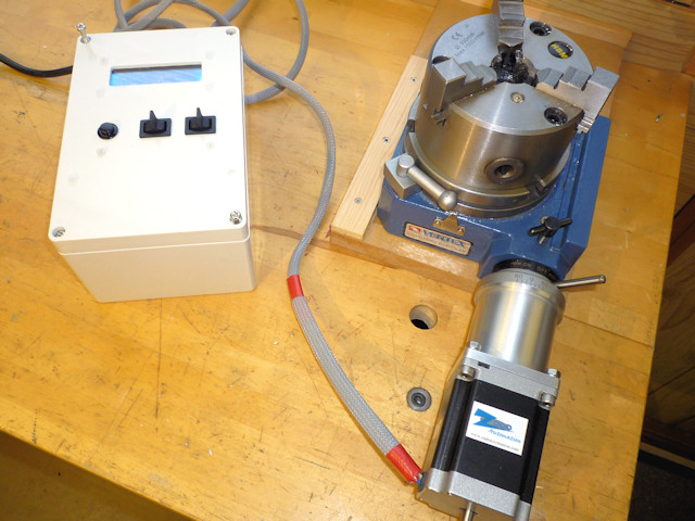
Image-based modeling is the process of reconstructing the three-dimensional geometry and the surface appearance of a real object from its two-dimensional images. In typical applications [1] images are acquired in a controlled environment. In order to achieve a 360° view of a complex object, the scanning must be repeated from different perspectives. Then, acquisition performed from different viewpoints needs to be registered, to reconstruct the full object geometry. The easiest solution to this issue is the manual point cloud registration, which is generally based on the 3-2-1 procedure: the first rough registration is manually provided by selecting three or more corresponding points on the clouds. Then, an iterative closest-point algorithm is run to refine the manual registration [2]. This procedure is robust and versatile, and it does not impose any constraints in terms of scanning perspective, but it requires long processing times. The procedure can be accelerated by gluing markers on the target surface, which can help the user to manually select the corresponding points, or can even allow for automatic algorithms [3]. Nevertheless, the marker placement may be cumbersome and also impossible to use where the surface cannot be altered. An alternative solution to this problem is represented by the use of turntables, which have proven to be effective in the reconstruction of complex shapes [4,5]. The object to be scanned can be placed on a turntable, and a stereo-camera system acquires images, while both orientation and placement of the item are changed within the work space by rotating the table by known angles. The use of a rotary table imposes a constraint to the possible scanning orientations, which can help the development of automatic algorithms to register the point clouds [6,7]. In addition, knowing the precise position and orientation of the turntable axis can further improve the registration step [8,9,10]. To this extent, a proper calibration of the acquisition system is necessary to obtain satisfying results.
Although technical literature well addresses the camera calibration problem, the extraction of the rotation axis of the turntable with reference to the fixed camera coordinate frame still deserves attention. Many different approaches have been found dealing with single-axis calibration: Mülayim et al. [23] proposed a multi-image approach capable of extracting the rotation axis of a single-axis turntable with respect to the camera coordinate frame. Li et al. [24] calibrated the rotation axis by means of a test sphere with a known diameter mounted on the turntable, similarly to [25]. Bi et al. [26] used a cuboid block and edge detection to assess the rotation axis. Langming et al. [27] developed a procedure based on the scanning of a cylindrical specimen. Ye et al. [28] used a planar specimen acquired in different orientations, basing the calibration on the intersection lines between subsequent planar surfaces. Chen et al. [29] formalized the problem as a constrained global optimization problem. However, these techniques do not generalize when a multi-axis turntable is considered, since each axis has to be calibrated separately, one after the other. Furthermore, no strict information about the placement of the calibration target as well as the number of images to be acquired is given in order to obtain acceptable results.
In this study, a novel approach for the calibration of a two-axis turntable is proposed. At first, a mathematical model for the rotation of a point attached to the turntable has been formalized and exploited in order to provide a minimum least-squares estimation of the two rotation axes as well as their distance with respect to the reference camera. Afterwards, a further analysis, based on optimal conditions to calibrate the rotary table, was conducted in order to optimize the estimates of the calibration process. Optimal conditions are considered to be the number and the orientation of placements of the calibration board with respect to the stereo-camera system. Qualitative criteria are finally provided based on experimental results.
The idea of an inexpensive, compact yet expandable platform for the polar measurement of electroacoustic devices has been in our minds for a long time. The aim of this project is not to replace commercially available products such as the industry-standard Outline ET250-3D turntable which we do recommend for the polar measurement of loudspeaker boxes. Nevertheless, we always found a market niche void in the polar measurement applications of small and light electro-acoustical devices.
Development of such turntable devices in the past required significant investment. Specific mechanical and motor control design skills were needed, leading to both costly and time-consuming processes. Recent developments in mechatronics and 3D printing allow to design and build a cost-effective solution. Our aim is to create a device that can be easily built with off-the-shelf parts, and at the same time can be tailored to specific customer’s needs using minimal modifications. This can be achieved using a ball-bearing swivel plate driven by a stepper motor controlled by an Arduino microcontroller running Grbl firmware.
In our build, we decided to use a small yet inexpensive swivel bearing plate that can be easily found in online shops. Everything in our design turns around, literally, to this choice. These plates can be found online using the keywords “Lazy Susan Hardware” (https://en.wikipedia.org/wiki/Lazy_Susan) and are commonly used for kitchen turntables and rotating stools. Among all possibilities we chose a small and compact “3-inch” model, which can withstand a weight up to 60 kg.:
The driver can be connected using few components to the Arduino board, but we wanted to reduce the burden of soldering to a minimum, thus we found two possible solutions with Arduino shields. Using Arduino Uno a possible solution is found on the market as “Arduino CNC shield V3”, this is a shield that can host up to 4 A4988 motor drivers:
We liked most the compactness and sleek elegance of Arduino Nano and we were able to find a motor shield for it. This can be found as “Arduino CNC shield V4”:
To reduce the time-to-market and reuse all possible components available we decided to not write a custom firmware for the Arduino board and instead use the widely adopted Grbl firmware. This allows sending commands to the turntable using standard CNC G-code and Grbl specific features. Both Arduino CNC shields shown here are compatible with Grbl.
Following the above choices, we designed a structure to hold together the swivel plate and the motor, providing a belt mechanism to drive the table rotation.
Since we want the turntable to be used on a bench and also mounted on a loudspeaker stand with a standard diameter of 35 mm, we designed a part that fits into the structure and also acts as a base to mount the swivel plate:
To complete the turntable we designed a lightweight plate that is bolted on top of the swivel plate pulley. This allows for easier placement of the loudspeaker to be measured.
1. Create your own shield, instruction on how to connect an A4988 driver to the Arduino board are very easy to find on the Internet. You will need only to add a capacitor and provide the connections.
Note: The .stl collection features also a spacer.stl part which is a 14 mm ring to be eventually placed between pulley and tabletop. In this case you will need 30 mm screws. This part move away the tabletop from the motor shaft and belt, in some cases it can be useful such when you have loudspeaker boxes with foots that can jam into the belt.
Tension the belt by sliding the motor plate to the left, do not overtight the belt. Once the tension is correct, tighten the motor plate screws to the beam structure. The belt tension can be optimized later during turntable testing.
First of all the Arduino should be loaded with Grbl firmware. At the time of writing the latest Grbl version is 1.1 and we carried out our tests using this version.
Follow the instruction to compile and load Grbl to the Arduino (there are also Grbl .ino binary files available on the Internet which you can load to the board using a binary sketch uploader).
The remaining electronics assembly is straightforward, just put the Arduino Nano onto the CNC Shield V4 and an A4988 motor driver onto the x-axis plug.
The motor connector has no polarity, thus there is a 50% chance to plug it correctly. By correctly we mean that a positive value of the x-axis in Grbl should match a clockwise rotation of the turntable.
Be careful as we actually blew out two Arduinos and one A4988 driver in this way during development. If you need to change the motor connector polarity, power off the CNC Board before.
Now we can try to move the first steps with our turntable. With the electronics powered up and connected to the PC, we can open the Serial Monitor tool of the Arduino IDE and send the first moving command to the turntable.
Notice that there is a little hysteresis at the end of the rotation due to the swivel plate tolerance and belt tension, this is clearly visible when the table is unloaded but disappears when under load. We think this is related to the swivel plate’s simple mechanical structure. The unloaded top plate, which is connected to the pulley, tends to flex when the belt tensions it. When loaded the weight tends to counteract the belt tension force.
We can send back the turntable to the starting position using a G1X0F360 command and try a complete revolution with higher speed by sending a G1X360F720 command followed by a G1X0F720 command. Check again for the smoothness of movement and eventually adjust belt tension and motor shaft pulley position if needed. Check also that the swivel plate bearing is free to move.
This control method and auto-save procedure are outdated since now CLIO software can directly control the turntable, nevertheless we will leave the following examples here as a future reference and to show a different approach.
The following Scilab code connects to the turntable and CLIO QC TCP/IP, and then runs a set of 73 measurements from -180 to 180 with 5 degrees step saving each measurement with the CLIO polar naming scheme:
The second function is GOTOangle(). This function sends the G1 movement command to the turntable using writeserial() and then polls the turntable Grbl status about each 0.1 s until the table is ‘Idle’, i.e. is not moving anymore. This function then release the control only when the table movement is complete.
CLIO 12.62 and CLIO Pocket 2.2 software both supports the Audiomatica Open Source Turntable. In fact, in this way, we support control for any device using Grbl (plus our practice to consider degrees instead of millimeters in Grbl settings).
The turntable can be also controlled using Serial Communication via CLIO QC scripting, or it is possible to create software (Or a MATLAB, Scilab or Phyton script) that can control both the turntable and CLIO QC using TCP/IP protocol. Examples of both approaches are provided.

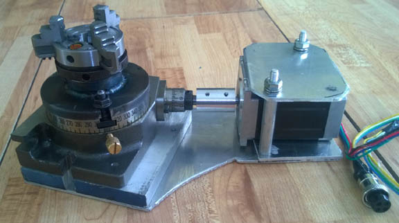
I was searching around on eBay and came across an interesting little trunnion table, link below. I had seen similar units, but they all used belt drive reductions, which from experience will not have enough reduction, and will likely be chatter with any real cutting, not to mention the belt is exposed. This unit however uses a harmonic drive to get a 50:1 reduction, with essentially zero detectable backlash. on top of that, it actually back drives the stepper motor. Harmonic drives are also sometimes called wave strain drives or flex spline drives. Anyways, the trunnion uses a couple of nema 23 steppers, and the holding torque is fantastic, even with a cheap stepper driver. For simplicity I"m using an arduino based controller that runs grbl 1.1f, and a couple of 5-30v inductive switches, links below. The controller can be controlled by sending gcode over the rx and tx pins, aka rs-232. The trunnion unit itself is very beefy for what it is, and has what look to be waterproof seals around all the bearings, so with a bit more sealing on the motors it can probably handle coolant usage.
Link to buy on ebay, although I got mine through aliexpress for cheaper. CNC Rotary axis Harmonic Gearbox Dividing Head 5th 4th Axis 50:1 reduction ratio | eBay

This library enables you to use Hardware-based PWM channels on Arduino AVR ATtiny-based boards (ATtiny3217, etc.), using megaTinyCore, to create and output PWM to pins.
This library enables you to use ISR-based PWM channels on Arduino AVR ATtiny-based boards (ATtiny3217, etc.), using megaTinyCore, to create and output PWM any GPIO pin.
Small low-level classes and functions for Arduino: incrementMod(), decToBcd(). strcmp_PP(), PrintStr, PrintStrN, printPad{N}To(), printIntAsFloat(), TimingStats, formUrlEncode(), FCString, KString, hashDjb2(), binarySearch(), linearSearch(), isSorted(), reverse(), and so on.
Cyclic Redundancy Check (CRC) algorithms (crc8, crc16ccitt, crc32) programmatically converted from C99 code generated by pycrc (https://pycrc.org) to Arduino C++ using namespaces and PROGMEM flash memory.
Various sorting algorithms for Arduino, including Bubble Sort, Insertion Sort, Selection Sort, Shell Sort (3 versions), Comb Sort (4 versions), Quick Sort (3 versions).
Date, time, timezone classes for Arduino supporting the full IANA TZ Database to convert epoch seconds to date and time components in different time zones.
Clock classes for Arduino that provides an auto-incrementing count of seconds since a known epoch which can be synchronized from external sources such as an NTP server, a DS3231 RTC chip, or an STM32 RTC chip.
Useful Arduino utilities which are too small as separate libraries, but complex enough to be shared among multiple projects, and often have external dependencies to other libraries.
Fast and compact software I2C implementations (SimpleWireInterface, SimpleWireFastInterface) on Arduino platforms. Also provides adapter classes to allow the use of third party I2C libraries using the same API.
Enables Bluetooth® Low Energy connectivity on the Arduino MKR WiFi 1010, Arduino UNO WiFi Rev.2, Arduino Nano 33 IoT, Arduino Nano 33 BLE and Nicla Sense ME.
Fully Asynchronous UDP Library for RASPBERRY_PI_PICO_W using CYW43439 WiFi with arduino-pico core. The library is easy to use and includes support for Unicast, Broadcast and Multicast environments.
The last hope for the desperate AVR programmer. A small (344 bytes) Arduino library to have real program traces and to find the place where your program hangs.
An Arduino library that takes input in degrees and output a string or integer for the 4, 8, 16, or 32 compass headings (like North, South, East, and West).
AS7341 is a 11 channel visible light sensor, which can measure 8 wavelengths of visible light, suitable for color detection, light color temperature detection and other scenes(SKU:SEN0365)
Directly interface Arduino, esp8266, and esp32 to DSC PowerSeries and Classic security systems for integration with home automation, remote control apps, notifications on alarm events, and emulating DSC panels to connect DSC keypads.
This library enables you to use Hardware-based PWM channels on Arduino AVRDx-based boards (AVR128Dx, AVR64Dx, AVR32Dx, etc.), using DxCore, to create and output PWM.
This library enables you to use ISR-based PWM channels on Arduino AVRDx-based boards (AVR128Dx, AVR64Dx, AVR32Dx, etc.), using DxCore, to create and output PWM any GPIO pin.
Small and easy to use Arduino library for using push buttons at INT0/pin2 and / or any PinChangeInterrupt pin.Functions for long and double press detection are included.Just connect buttons between ground and any pin of your Arduino - that"s itNo call of begin() or polling function like update() required. No blocking debouncing delay.
Arduino library for controlling standard LEDs in an easy way. EasyLed provides simple logical methods like led.on(), led.toggle(), led.flash(), led.isOff() and more.
OpenTherm Library to control Central Heating (CH), HVAC (Heating, Ventilation, Air Conditioning) or Solar systems by creating a thermostat using Arduino IDE and ESP32 / ESP8266 hardware.
WizFi360/ESP8266/ESP32-AT library for Arduino providing an easy-to-use way to control WizFi360/ESP8266-AT/ESP32-AT WiFi shields using AT-commands. For AVR, Teensy, SAM DUE, SAMD21, SAMD51, STM32, nRF52, SIPEED_MAIX_DUINO and RP2040-based (Nano_RP2040_Connect, RASPBERRY_PI_PICO, etc.) boards using WizFi360/ESP8266/ESP32 AT-command shields.
ezTime - pronounced "Easy Time" - is a very easy to use Arduino time and date library that provides NTP network time lookups, extensive timezone support, formatted time and date strings, user events, millisecond precision and more.
A library for implementing fixed-point in-place Fast Fourier Transform on Arduino. It sacrifices precision and instead it is way faster than floating-point implementations.
The GCodeParser library is a lightweight G-Code parser for the Arduino using only a single character buffer to first collect a line of code (also called a "block") from a serial or file input and then parse that line into a code block and comments.
Arduino library for the Flysky/Turnigy RC iBUS protocol - servo (receive) and sensors/telemetry (send) using hardware UART (AVR, ESP32 and STM32 architectures)
An Arduino library to control the Iowa Scaled Engineering I2C-IRSENSE ( https://www.iascaled.com/store/I2C-IRSENSE ) reflective infrared proximity sensor.
Treat PCF8574, MCP23017 and Shift registers like pins, matrix keypad, touch screen handler, button press and rotary encoder management (switches) on any supported IO (including DfRobot & Joysticks) with event handling, interchangable AVR/I2C(AT24) EEPROMs.
Convinient way to map a push-button to a keyboard key. This library utilize the ability of 32u4-based Arduino-compatible boards to emulate USB-keyboard.
This library allows you to easily create light animations from an Arduino board or an ATtiny microcontroller (traffic lights, chaser, shopkeeper sign, etc.)
LiquidCrystal fork for displays based on HD44780. Uses the IOAbstraction library to work with i2c, PCF8574, MCP23017, Shift registers, Arduino pins and ports interchangably.
This library enables you to use ISR-based PWM channels on RP2040-based boards, such as Nano_RP2040_Connect, RASPBERRY_PI_PICO, with Arduino-mbed (mbed_nano or mbed_rp2040) core to create and output PWM any GPIO pin.
Arduino library for MCP4728 quad channel, 12-bit voltage output Digital-to-Analog Convertor with non-volatile memory and I2C compatible Serial Interface
This library enables you to use ISR-based PWM channels on an Arduino megaAVR board, such as UNO WiFi Rev2, AVR_Nano_Every, etc., to create and output PWM any GPIO pin.
Replace Arduino methods with mocked versions and let you develop code without the hardware. Run parallel hardware and system development for greater efficiency.
A library package for ARDUINO acting as ModBus slave communicating through UART-to-RS485 converter. Originally written by Geabong github user. Improved by Łukasz Ślusarczyk.
This library enables you to use ISR-based PWM channels on an nRF52-based board using Arduino-mbed mbed_nano core such as Nano-33-BLE to create and output PWM any GPIO pin.
This library enables you to use ISR-based PWM channels on an nRF52-based board using Adafruit_nRF52_Arduino core such as Itsy-Bitsy nRF52840 to create and output PWM any GPIO pin.
An Arduino library for the Nano 33 BLE Sense that leverages Mbed OS to automatically place sensor measurements in a ring buffer that can be integrated into programs in a simple manner.
his library enables you to use Hardware-based PWM channels on RP2040-based boards, such as Nano_RP2040_Connect, RASPBERRY_PI_PICO, with either Arduino-mbed (mbed_nano or mbed_rp2040) or arduino-pico core to create and output PWM to any GPIO pin.
This library enables you to use SPI SD cards with RP2040-based boards such as Nano_RP2040_Connect, RASPBERRY_PI_PICO using either RP2040 Arduino-mbed or arduino-pico core.
This library enables you to use ISR-based PWM channels on RP2040-based boards, such as ADAFRUIT_FEATHER_RP2040, RASPBERRY_PI_PICO, etc., with arduino-pico core to create and output PWM any GPIO pin.
The most powerful and popular available library for using 7/14/16 segment display, supporting daisy chaining so you can control mass amounts from your Arduino!
Provides methods to retrieve instant and peak values from the ADC input. The Arduino library SensorWLED splits the input from a varying analog signal from the ADC into components, i.e., provides the capability of a sample-and-hold circuit.
Enables smooth servo movement. Linear as well as other (Cubic, Circular, Bounce, etc.) ease movements for servos are provided. The Arduino Servo library or PCA9685 servo expanders are supported.
Enables reading and writing on SD card using SD card slot connected to the SDIO/SDMMC-hardware of the STM32 MCU. For slots connected to SPI-hardware use the standard Arduino SD library.
Menu library for Arduino with IoT capabilities that supports many input and display devices with a designer UI, code generator, CLI, and strong remote control capability.
A library for creating Tickers which can call repeating functions. Replaces delay() with non-blocking functions. Recommanded for ESP and Arduino boards with mbed behind.
This library enables you to use Interrupt from H


 8613371530291