
rotary table chuck adapter plate free sample

6" base adapter plate is ideal to use on 6" rotary tables of either 3 or 4 slots to mount either 4" , 5" 3-jaw ,6-jaw or 4-jaw self-centering lathe chucks.

My situation is slightly different. I bought an indexing head that can swivel from parallel with the base or table to being at right angles to the base or table. The indexing head I bought specifically because it had a threaded spigot the same as my lathe"s chucks. I can easily transfer either my 3 or 4-jaw chuck from the lathe to the mill in a couple of minutes... while never removing the work from the chuck.
What you need to make is a spigot with the same thread pitch and OD as the spindle on your lathe. Make it as carefully as possible so that it is a close fit paying the most attention to reference surfaces. If there is a center reference on your rotab (blind hole in the center) make the spigot so that it will fit in there and center itself WRT axis of the rotab. Provide some means of clamping it to the rotab table such as a flange with 4 bolt holes. Keep this adapter as short as possible.

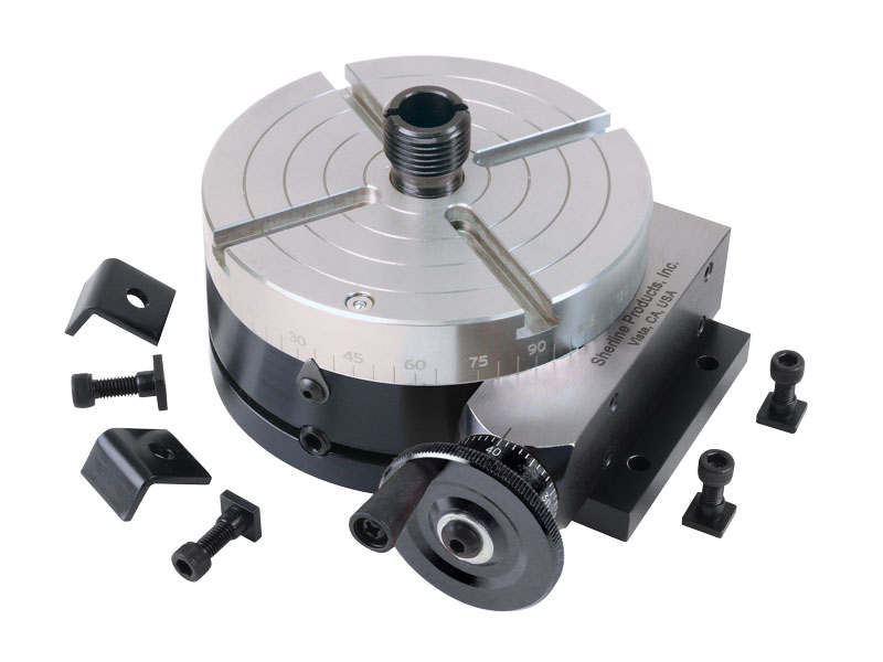
This is a modification of our 4″ Manual Rotary Table. This modification came about after requests from our laser engraving customers. They wanted a rotary table that had a larger through-hole to which they could mount our chucks.
This version of the Sherline rotary table has a Nickel-Teflon plating on the tabletop because it was designed to be used in an everyday production environment. This gives the table a rust-resistant surface that is hard and has added lubrication qualities.
The table is 2″ high and 4″ (100mm) in diameter. The main components have been machined from solid bar stock steel, and the complete unit weighs seven pounds. The table has been engraved with a laser, giving sharp and precise lines every 5°, numbered every 15°. These lines are calibrated with the 72-tooth worm gear that is driven by the handwheel or stepper motor. The handwheel is divided into 50 parts, making each line on the handwheel 1/10°. This allows a circle to be divided into 3600 increments without interpolation. Seventy-two revolutions of the handwheel rotate the table one revolution.
NOTE: You can have your manual rotary table upgraded to CNC-ready, but this is done as a factory-only replacement. You will need to ship your manual rotary table back to our factory for the conversion.

Years ago, before I learned CNC, I owned a Phase II 8″ horizontal/vertical rotary table that I purchased from Kap Pullen’s Getmachinetools.com store. He has them at a good price, BTW, and he’s a darned nice fellow to deal with as well as being a frequent HSM contributor. Anyway, its a nice little table, but I hadn’t done a whole lot with it for quite a while after purchasing it. As is so often the case, one day, a project landed on my doorstep and I was glad to have it.
Before I could get started, however, I had to make some accessories for it. Basically, I needed some T-Nuts to fit the table, as well as a little fixture that makes it easy to hold a plate up off the table through a hole in the center so you can machine it. The latter, what I call a “plate machining fixture”, was inspired by something similar I saw the Widgitmaster of CNCZone fame using to make Dremel clamps for his mini-router:
The Plate Maching Fixture and 3 Homemade T-Nuts. T-Nuts are easy to make: square a block to the proper dimensions, mill the side reliefs, drill, and tap. These are much smaller than the mill’s Bridgeport standard T-slots, so I made them myself and I’m using 1/4-20 bolts with them. They’re made of mild steel.
I turned the round spigot using the 4-jaw on the lathe. I’m making the fixture out of MIC-6 aluminum plate, which is pre-ground very flat on the sides. This is a 5 inch by 3 inch piece. I’ve clamped it to the rotab using my T-nuts and the regular mill clamps and step blocks. It is sitting on parallels to make sure I don’t cut into the table. You can also see how I’ve clamped the rotary table to the mill table using a big cast iron V-block I have. You can never have to many blocks with precision faces hanging around!
Having a 4-jaw chuck on your rotary table is mighty handy! Because it’s a 4-jaw, you can dial in the workpiece by adjusting the jaws until it is perfectly concentric with the table’s axis of rotation. The best way is to make an adapter plate that attaches to the back of the chuck in the same way that your lathe does so you can exchange lathe tooling with the rotab. Here is an example:
For the example, the chuck is threaded onto the adaptor plate, and then the holes in the adapter plate’s flange are used to bolt down to T-nuts on the table.
In my case, I bought a 4-jaw from Shars brand new, and simply drilled some through-holes in the chuck to mount to the table directly without an adapter plate:
First, you want to make sure your part is properly centered on the table. To do that, I clamp the table down on the mill table (no special place is needed), put my Indicol indicator holder on the mill spindle, and find some round feature on the part to indicate on. For example, on the plate milling fixture above, indicate on the round boss, or on the center hole. Spin the table and bump the part in until spinning the table doesn’t move the indicator.
Second, locate the center of rotation directly under the mill spindle. You can simply use the X and Y table handwheels to do this. Use that Indicol to indicate off of a circular feature you want centered under the spindle. Turn the indicol around on the spindle and adjust the handwheels until the indicator stays put relative to the spindle position. A Blake Coaxial indicator will make this last even simpler.
When you’re rounding partially by cranking a part around on the rotary table, it’s really easy to go a little too far and screw things up. The answer is to drill the end points to make the exact stopping point on the rotab a lot less sensitive:
Centering with a Blake indicator is really fast, but what if you don’t have a Blake, or worse, what if your mill is too small to accomodate one? Here is a nice solution I found on a German site. This fellow has made an ER collect fixture for his rotary table, and has taken care that when installed on the table, the axis of the collet is aligned with the table’s axis. He can then place a dowel or other straight pin in the collet and line up until it will go into a similarly sized collet on the spindle. Nice trick! It’s similar to how Widgitmaster showed me to align a drill chuck on a QCTP to the lathe centerline with a dowel pin held in the lathe chuck.
I"m a wanna-be machinist newbie. I have a small mill (no lathe). I obtained this small 6" rotary table (a Griz product). I would like to get a small 3-jaw chuck mounted to it, but have NO CLUE as to how to choose a chuck that will be compatible with this RoTab. Am I looking for a 6" chuck? Or 4"? I can"t go too "tall" or I waste all my Z axis. I don"t even know how the chuck would mount to the RoTab. The hole in the center is a MT#2, would a chuck use the MT? Or attached how?
Can someone guide me to some options regarding how to get a chuck on here, where to find the components needed? I am not looking for gold-plated accuracy. (It"s just an inexpensive $900 ChiCom mill with an inexpensive $250 ChiCom RoTab. Not proud of it, but I"m lucky to have it, and it works good enough.) In fact I"d love to buy a chuck used if possible and save some coin. Ideas?
More info on my intended useage of chuck-on-rotab, if you are interested: This RoTab will mount horizontal or vertical. With the RoTab in the vertical position, with its associated tailstock, I believe you can "fake" some lathe operations on a mill. I need to do some small lathe operations with it, which will entail bringing down an endmill to the work and then slowly turning the RoTab. So sort of reverse of a lathe, in this setup the bit is powered and the work is being turned slowly by hand. Yeah, I wish had a lathe but in this obanomy, you make do with what you got.
Alternately, I think I can do some vertical lathing without the RoTab. If the stock is small enough to go into the mill"s chuck (5/8 max) and stout enough to hang free, some lathing can be done by clamping a lathe bit in the vise and running it up and down the work using the Z axis. For small work only.
I suppose you could also chuck a larger round piece in the rotab/chuck (with the rotab/chuck in the horizontal position, and the work sticking up vertically), and use an endmill to make bushings, and other short, squat round work, etc. by spinning the work in the rotab/chuck against the endmill.

I have a 5" 4 jaw that I use on the 9x20. I also have a nice Phase II 6" rotary table. I was going to buy another 6" 4 jaw for the rotary table and just drill it between the jaws and run socket head screws through it to T-nuts. I may still do that, just because the plain back 4 jaw 6" chucks are cheap.
Then I thought, why not just use the 5". I haven"t done it yet, but the idea I had was to use a 6" chuck adapter threaded for the 9x20 (have it already) and turn the register to catch the back of the 5" chuck - basically, make a regular lathe chuck mount. With the check mounted and checked out, turn the diameter of the adapter to match the rotary table as required. Then remove the chuck, mount the adapter on a faceplate backwards and face off the back of the plate to make it flat all the way across. Alternately, I could just mill the threaded mounting boss off the back side. Take what"s now a chuck mounting "puck" and punch 4 holes in the outer diameter clear of where the chuck mounts to catch some t-nuts on the rotary. Mount chuck to puck, puck to table and done. If the chuck is needed on the lathe, it"s just put back on its old 5" adapter and mounted on the lathe. One chuck doing double duty. More engineering, but hey - I need practice.

I"d like to be able to put my 10" & 12" A (not sure which one, but short tapered nose, four bolts) series 3 & 4 jaw chucks on my 10" Phase II rotary table for doing bolt holes, gears; I don"t happen to have any smaller chucks. The center of the table has a MT2 taper I believe, which might serve to indicate where the center is but isn"t strong enough to coerce the chuck into the right position, even sitting free on the table. I guess the 4 jaw doesn"t need to be centered - only the work held by the chuck does - but since many things that need bolt patterns are already round, I could save some time by using the 3 jaw.

A chuck is a specialized type of clamp used to hold an object with radial symmetry, especially a cylinder. In a drill, a mill and a transmission, a chuck holds the rotating tool; in a lathe, it holds the rotating workpiece.
Chucks commonly use jaws to hold the tool or workpiece. The jaws (sometimes called dogs) are typically arranged in a radially symmetrical pattern like the points of a star. Jawed chucks may require a wrench-like device called a chuck key to be tightened or loosened, but other jawed chucks may be tightened or loosened by hand force alone, offering convenience at the expense of gripping force. Chucks on some lathes have jaws that move independently, allowing them to hold irregularly shaped objects. More complex designs might include specially shaped jaws, greater numbers of jaws, or quick-release mechanisms.
Instead of jaws, a chuck may use magnetism, vacuum, or collets, which are flexible collars or sleeves that fit closely around the tool or workpiece and grip it when squeezed.
Self-centering three-jaw chuck and key with one jaw removed and inverted showing the teeth that engage in the scroll plate. The scroll plate is rotated within the chuck body by the key, the scroll engages the teeth on the underside of the jaws which moves the three jaws in unison, to tighten or release the workpiece.
A self-centering chuck, also known as a scroll chuck,dogs (usually called jaws), interconnected via a scroll gear (scroll plate), to hold onto a tool or workpiece. Because they most often have three jaws, the term three-jaw chuck without other qualification is understood by machinists to mean a self-centering three-jaw chuck. The term universal chuck also refers to this type. These chucks are best suited to grip circular or hexagonal cross-sections when very fast, reasonably accurate (±0.005 inch [0.125 mm] TIR) centering is desired.
Sometimes this type of chuck has four or six jaws instead of three. Four-jawed chucks are primarily useful for gripping square or octagon material, while six-jawed chucks hold thin-walled tubing and plastic materials with minimum distortion.
There are hybrid self-centering chucks that have adjustment screws that can be used to further improve the concentricity after the workpiece has been gripped by the scroll jaws. This feature is meant to combine the speed and ease of the scroll plate"s self-centering with the run-out eliminating controllability of an independent-jaw chuck. The most commonly used name for this type is a brand name, Set-Tru. To avoid undue genericization of that brand name, suggestions for a generic name have included "exact-adjust".
Top: an assembled keyless chuck. This type of chuck is tightened by twisting the body using firm hand pressure only. While convenient, this feature can cause the chuck to tighten too much when high torque is applied. Bottom: the widely used keyed type of drill chuck with its key. The arbor is shown separately to the right. These chucks require a toothed key to provide the necessary torque to tighten and loosen the jaws. When the key is turned its teeth mate with teeth on the chuck, turning an internal screw which in turn moves the threaded jaws in or out along a tapered surface. The taper allows the jaws to clamp drill shanks of a range of diameters. The end view shows the three small jaws that slide within the body.
A drill chuck is a specialised self-centering, three-jaw chuck, usually with capacity of 0.5 in (13 mm) or less, and rarely greater than 1 in (25 mm), used to hold drill bits or other rotary tools. This type of chuck is used on tools ranging from professional equipment to inexpensive hand and power drills for domestic use.
Some high-precision chucks use ball thrust bearings to reduce friction in the closing mechanism and maximize drilling torque. One brand name for this type of chuck, which is often genericized in colloquial use although not in catalogs, is Super Chuck.
A pin chuck is a specialized chuck designed to hold small drills (less than 1 mm (0.039 in) in diameter) that could not be held securely in a normal drill chuck. The drill is inserted into the pin chuck and tightened; the pin chuck has a shaft which is then inserted into the larger drill chuck to hold the drill securely. Pin chucks are also used with high-speed rotary tools other than drills, such as die grinders and jig grinders.
An older and larger 4 jaw chuck. Note how it is able to grip an irregularly cut piece of used metal. Though not found on small chucks it is common for larger chucks (the one in the second photo was made around 1900 and is 24" in diameter) to have many of the features of a faceplate. The jaws are stepped on one side and full height for gripping on the other and are reversible. Generally the jaws are usable for holding either outside as shown here, or inside as in gripping the inside of a pipe.
On an independent-jaw chuck, each jaw can be moved independently. Because they most often have four jaws, the term four-jaw chuck without other qualification is understood by machinists to mean a chuck with four independent jaws. The independence of the jaws makes these chucks ideal for (a) gripping non-circular cross sections and (b) gripping circular cross sections with extreme precision (when the last few hundredths of a millimeter [or thousandths of an inch] of runout must be manually eliminated). The non-self-centering action of the independent jaws makes centering highly controllable (for an experienced user), but at the expense of speed and ease. Four-jaw chucks are almost never used for tool holding. Four-jaw chucks can be found on lathes and indexing heads.
Self-centering chucks with four jaws also can be obtained. Although these are often said to suffer from two disadvantages: inability to hold hex stock, and poor gripping on stock which is oval, only the latter is true. Even with three jaw self centering chucks, work which is not of uniform section along the work (and which is not free of spiral or "wind") should not be gripped, as the jaws can be strained and the accuracy permanently impaired.
A spider is a simple, relatively inexpensive, limited-capability version of an independent-jaw chuck. It typically consists of a ring of metal with screw threads tapped radially into it, in which screws (hex cap, socket hex cap, or set screws) serve as independent jaws. Spiders can serve various purposes:
For special purposes, chucks are available with six or eight jaws. These are usually of the self-centering design, and may be built to very high standards of accuracy. However, it is a misconception that such chucks necessarily offer more precision in holding solid workpieces than conventional three-jawed self-centering chucks. Indeed, hot-rolled or other imperfectly round workpieces may "teeter" insecurely between opposing jaws of scroll chucks having even numbers of jaws, in the same manner that a four-legged stool teeters on a rough floor while a three-legged stool never does. The primary purpose of six- and eight-jawed chucks is to hold thin-walled tubing with minimum deformation. By having twice as many clamping points, a six-jaw chuck induces less than half as much clamping distortion in a thin-walled workpiece, compared to a three-jawed chuck.
Two-jaw chucks are available and can be used with soft jaws (typically an aluminium alloy) that can be machined to conform to a particular workpiece. It is a short conceptual leap from these to faceplates holding custom fixtures, wherein the part is located against fixed stops and held there with toggle clamps or toe clamps.
Many chucks have removable jaws (often the top part is removable leaving the base or "master jaw" assembled with the scroll), which allows the user to replace them with new jaws, specialised jaws, or soft jaws. Soft jaws are made of soft materials such as soft (unhardened) metal, plastic, or wood. They can be machined as needed for particular setups. The typical interface between the master jaw and the removable jaw is a matching pair of serrated surfaces, which, once clamped by the mounting screws, cannot allow relative slipping between the two parts.
A collet, one type of chuck, is a sleeve with a (normally) cylindrical inner surface and a conical outer surface. The collet can be squeezed against a matching taper such that its inner surface contracts to a slightly smaller diameter, squeezing the tool or workpiece whose secure holding is desired. Most often this is achieved with a spring collet, made of spring steel, with one or more kerf cuts along its length to allow it to expand and contract. An alternative collet design is one that has several tapered steel blocks (essentially tapered gauge blocks) held in circular position (like the points of a star, or indeed the jaws of a jawed chuck) by a flexible binding medium (typically synthetic or natural rubber). The Jacobs Rubber-Flex brand is a name that most machinists would recognize for this type of collet chuck system.
Regardless of the collet design, the operating principle is the same: squeeze the collet radially against the tool or workpiece to be held, resulting in high static friction. Under correct conditions, it holds quite securely. Almost all collet chucks achieve the radial squeezing motion via moving one or more male-female pairs of tapered (conical) surfaces axially, which produces the radial squeezing in a highly concentric manner. Depending on the collet design, it can be either pulled (via a threaded section at the rear of the collet) or pushed (via a threaded cap with a second taper) into a matching conical socket to achieve the clamping action. As the collet is forced into the tapered socket, the collet will contract, gripping the contents of the inner cylinder. (The axial movement of cones is not mandatory, however; a split bushing squeezed radially with a linear force—e.g., set screw, solenoid, spring clamp, pneumatic or hydraulic cylinder—achieves the same principle without the cones; but concentricity can only be had to the extent that the bushing"s diameters are perfect for the particular object being held. Thus only in toolroom contexts, such as machine tool tooling creation and setup, is this common.)
One of the corollaries of the conical action is that collets may draw the work axially a slight amount as they close. Collet chuck systems that make no provision to prevent this draw-in are often called draw-in collet chucks, in contrast to systems which circumvent this movement, usually by pushing the tapered closing ring toward the collet rather than pulling the collet into the ring. Such non-draw-in types are often called "dead-length" or "non-draw-in" collet chucks. Draw-in is not always a problem, but avoiding it can be helpful on some work where failing to account for it might result in inaccuracy on part overall length, shoulder lengths, etc.
Collets are most commonly found on milling machines, lathes, wood routers, precision grinders, and certain handheld power tools such as die grinders and rotary tools. There are many different systems, common examples being the ER, 5C, and R8 systems. Collets can also be obtained to fit Morse or Brown and Sharpe taper sockets.
Typically collets offer higher levels of precision and accuracy than self-centering chucks, and have a shorter setting up time than independent-jaw chucks. The penalty is that most collets can only accommodate a single size of workpiece. An exception is the ER collet which typically has a working range of 1 mm (about 0.04 in).
Developed by Bosch in 1975 for hammer drills, the SDS System uses an SDS Shank which is a cylindrical shank with indentations to be held by the chuck.
A 10 mm shank with two open grooves interacting with the driving wedges and two closed grooves held by locking balls. This is the most common size and takes a hammer up to 4 kg. The wedges grip an area of 75 mm2 (0.116 sq in) and the shank is inserted 40 mm into the chuck.
Commercial production machining now makes use of increasingly advanced chucks which have not only indexable positioning but also indexable clamping.hydraulically controlled. The clamping is often done with each pair of jaws consisting of one fixed jaw and one movable jaw (hydraulically actuated), thematically similar to advanced milling vises. This method of clamping brings the high precision and repeatability of such vises to a chucking application. Such chucks offer the centering precision of traditional independent-jaw chucks with the chucking speed and ease of traditional three-jaw self-centering scroll chucks. They have expensive initial cost (compared with traditional chucks), but such initial cost pays for itself and then lowers ongoing marginal costs in commercial production-run environments.
It is also possible nowadays to build CNC chucks in which the position and clamping pressure of each jaw can be precisely controlled with CNC, via closed-loop positioning and load monitoring. In essence, each jaw is one independent CNC axis, a machine slide with a leadscrew, and all four or six of them can act in concert with each other. Although this idea is conceptually interesting, the simpler chucking systems mentioned in the previous paragraph are probably a marketplace winner over this alternative for most applications, because they supply the same capabilities via a simpler, less expensive solution.
Used for holding ferromagnetic workpieces, a magnetic chuck consists of an accurately centred permanent magnet face. Electromagnets or permanent magnets are brought into contact with fixed ferrous plates, or pole pieces, contained within a housing. These pole pieces are usually flush with the housing surface. The part (workpiece) to be held forms the closing of the magnetic loop or path, onto those fixed plates, providing a secure anchor for the workpiece.
Commonly used for holding silicon wafers during lithography processes, an electrostatic chuck comprises a metal base-plate and a thin dielectric layer; the metal base-plate is maintained at a high-voltage relative to the wafer, and so an electrostatic force clamps the wafer to it. Electrostatic chucks may have pins, or mesas, the height of which is included in the reported dielectric thickness; a design by Sandia National Laboratory uses a patterned silicon-dioxide dielectric to form the pins.
A vacuum chuck is primarily used on non-ferrous materials, such as copper, bronze, aluminium, titanium, plastics, and stone. In a vacuum chuck, air is pumped from a cavity behind the workpiece, and atmospheric pressure provides the holding force. Vacuum produces a hold down pressure of 14.7 psi (101 kPa) at sea level, decreasing at higher elevations where the atmospheric pressure is lower. The decrease in holding pressure is roughly 0.5 psi per 1000" above sea level.
Tools: vise (especially with a wooden jig or soft jaw made for this purpose); hammer (especially nonmarring hammer or rubber mallet); arbor press or shop press (the latter two require skill to avoid damaging the chuck).
A backplate with threads may screw onto a threaded spindle nose (for lathe work) or onto an adapter plate with the same nose, to be mounted on the table of milling machines or surface grinding machines. This "threaded spindle nose" type of mounting was the typical method in the 19th century through 1930s. It is simple and useful, but the degree of control of concentricity is not quite good enough to be foolproof for high-speed, high-precision work (high precision can be achieved, but the time and skill involved in the setups makes it a poor choice now that better options exist, such as the cam-lock spindle noses described below). Threaded spindle noses are still built on new machine tools, but only of the low-end variety (hobbyist, least-expense MRO, etc.). High-capital manufacturing (where high upfront expense yields lowest possible unit expense for mid- to high-volume part counts of high-precision parts) has moved away from this type of mounting. The exact-adjust (Set-Tru) concept is one way to chase high concentricity on threaded spindle noses with some relative degree of ease.
A common solution on smaller lathes is a broad flanged end to the spindle with a concentric raised circular register matching a recess in the chuck or its backplate. The register is normally shallow and parallel sided and a light push fit in the female register of the chuck. The chuck is held in place with bolts through clearance holes that do not affect the alignment which is entirely provided by the register. This arrangement has excellent repeatability but is slow in a production situation.
A backplate with a female (self-releasing) taper may seat on the matching male taper of the tapered spindle nose (for lathe work) or of an adapter plate with the same nose, to be mounted on a table. This system improves the repeatability of the mounting concentricity down to a very small total indicated runout (TIR) value. Subtypes:
The chuck may be held against the taper with a threaded retainer ring (large thin nut), typically wrenched with a spanner wrench of the pin or hook variety. The peak of popularity for building this type of spindle nose was the 1940s and 1950s.
The chuck may be held against the taper with cam-lock posts that wedge into a stuck-fast position. Industry-standard spindle nose designs allow wide interchangeability. This cam lock spindle nose system replaced the earlier systems on most machine tools in the 1960s.
Many lathes that run collet chucks have dedicated collet-closer setups whereby there is no backplate, and the spindle nose contains the female taper for either the collet"s male outer taper, or a sleeve that will hold it. A hollow drawbar passes back through the headstock to its back side, where a closer mechanism is mounted. The latter allows easy, rapid opening and closing of the collet. The drawbar"s inner diameter determines the through-the-spindle bar diameter capacity of the lathe. Some collet-closer systems even allow opening and closing without stopping the spindle rotation. The closer on a manual lathe is either lever-style or handwheel-style. The closer on a CNC lathe is powered (electric, hydraulic, or pneumatic), and it may be controlled by various means: a foot pedal that the operator steps on when desired; a line in the program (for opening and closing under program control); or a button on the control panel.
The Jacobs type chuck, with three converging splines or jaws, is perhaps the most usual design. This one is tightened with a key, but some types may be sufficiently tightened by hand
The original forms of workholding on lathes were between-centers holding and ad hoc fastenings to the headstock spindle.Ad hoc fastening methods in centuries past included anything from pinning with clenching or wedging; nailing; lashing with cords of leather or fiber; dogging down (again involving pinning/wedging/clenching); or other types. Faceplates have probably been around at least since the era of medieval clock-makers.
Tooling similar to today"s chucks seems likely to have evolved from faceplate work, as workers using faceplates for repetitive work began to envision types of clamps or dogs for the faceplate that could be opened and closed in more convenient ways than repeated total disassembly and reassembly.
A chock was originally just a lump of wood. However, by 1703 it could be "… Chocks, belonging to the Screw-Mandrel".chuck: "On the end of the spindle … is screwed … a universal Chuck for holding any kind of work".
It is not clear how they were moved "equably" whether by a scroll or some other means.Simon Fairman (1792–1857) developed a recognisable modern scroll chuck as used on lathes.Austin F. Cushman (1830–1914) developed the ideas and sold chucks through his business, Cushman Industries.
At the start of the 20th century, Arthur Irving Jacobs developed the modern drill chuck. After bruising his knuckles on one of the old-fashioned spanner adjusted drill chucks, he developed a chuck in which the jaws moved axially in inclined slots. His drill chuck clearly did not originate with him, but his new type of drill chuck long ago displaced any earlier types that lacked the angled jaw movement and outer sleeve now found on all common drill chucks.
National and international standards are used to standardize the definitions, requirements, and test methods used for the performance evaluation of chucks. Selection of the standard to be used is an agreement between the supplier and the user and has some significance in the design of the chuck. In the United States, ASME has developed the B5.60 Standard entitled Workholding Chucks: Jaw-Type Chucks, which establishes requirements and methods for specifying and testing the performance of workholding chucks used primarily in turning operations.


 8613371530291