
little machine shop rotary table free sample
I have a mill made by Little Machine Shop. It is very similar to others such as those offered by Micro Mark, Harbor Freight and Grizzly, and - perhaps not in the same class - the Proxxon FF230. But just the same: they all have one thing in common: they use metric threads and that can cause some problems when interchanging accessories with those made on the basis of the US standard threads (for example Sherline).
After looking at the various options offered by Grizzly (their ‘two inch self-centering vise’), and the rotary table sold by Micro Mark at a much higher price, I went with the 4 inch rotary table and tilting table made by Sherline. The rotary table is a high quality tool and the tilting table is ok, but nothing fancy. However, the combination of the two gives me a lot of possible machining options.
I need to use metric bolts and T-nuts to hold the tilting table to my mill bed. But since the holes in the tilting base are US standard and don’t align with the mill table slots, I had to drill new holes in the tilting table base so it would. The four new holes are clearance holes for 6 mm cap screws and are spaced 1.78 inches apart.
The rotary table is designed to clamp to the tilting table, so now I can use it without having to make new adapters to mount it to my mill table. So, far so good.
How about chucks for the rotary table. You can buy them from Sherline, but I also have a mini lathe that has a three and a four jaw chuck. Again they are metric and that is where the rub lies. I don’t use the four jaw chuck very often and decided to make an adapter plate that would allow me to bolt the chuck to the rotary table. I used a ¼ inch thick aluminum plate and drilled the holes as shown in the drawing below.
The reason for the slots is that the hole-pattern in the Sherline table is all screwy and not spaced uniformly across the base plate. The two threaded holes used for the brackets to the rotary table could have been moved to 1.29 inches from center (the same as those to the right) instead of the 1.16 inch as it appears now.
·Mount the rotary table and tilting table along with one of the two chucks (three or four jaws). This is where the adapter plate comes into the picture.
·To machine horizontal slots in shafts, spars or other parts I can take the tilting table (with chuck mounted) and tilt it to 90 degrees. Sherline makes a tailstock for their mill to do just that (it mounts on their mill bed, not mine). I like to keep my 4 inch vise where it is and I think I can make an adapter to serve as the ‘tailstock’ using wood. Besides, how often would I need that?
Years ago, before I learned CNC, I owned a Phase II 8″ horizontal/vertical rotary table that I purchased from Kap Pullen’s Getmachinetools.com store. He has them at a good price, BTW, and he’s a darned nice fellow to deal with as well as being a frequent HSM contributor. Anyway, its a nice little table, but I hadn’t done a whole lot with it for quite a while after purchasing it. As is so often the case, one day, a project landed on my doorstep and I was glad to have it.
Before I could get started, however, I had to make some accessories for it. Basically, I needed some T-Nuts to fit the table, as well as a little fixture that makes it easy to hold a plate up off the table through a hole in the center so you can machine it. The latter, what I call a “plate machining fixture”, was inspired by something similar I saw the Widgitmaster of CNCZone fame using to make Dremel clamps for his mini-router:
I turned the round spigot using the 4-jaw on the lathe. I’m making the fixture out of MIC-6 aluminum plate, which is pre-ground very flat on the sides. This is a 5 inch by 3 inch piece. I’ve clamped it to the rotab using my T-nuts and the regular mill clamps and step blocks. It is sitting on parallels to make sure I don’t cut into the table. You can also see how I’ve clamped the rotary table to the mill table using a big cast iron V-block I have. You can never have to many blocks with precision faces hanging around!
Having a 4-jaw chuck on your rotary table is mighty handy! Because it’s a 4-jaw, you can dial in the workpiece by adjusting the jaws until it is perfectly concentric with the table’s axis of rotation. The best way is to make an adapter plate that attaches to the back of the chuck in the same way that your lathe does so you can exchange lathe tooling with the rotab. Here is an example:
For the example, the chuck is threaded onto the adaptor plate, and then the holes in the adapter plate’s flange are used to bolt down to T-nuts on the table.
In my case, I bought a 4-jaw from Shars brand new, and simply drilled some through-holes in the chuck to mount to the table directly without an adapter plate:
First, you want to make sure your part is properly centered on the table. To do that, I clamp the table down on the mill table (no special place is needed), put my Indicol indicator holder on the mill spindle, and find some round feature on the part to indicate on. For example, on the plate milling fixture above, indicate on the round boss, or on the center hole. Spin the table and bump the part in until spinning the table doesn’t move the indicator.
Second, locate the center of rotation directly under the mill spindle. You can simply use the X and Y table handwheels to do this. Use that Indicol to indicate off of a circular feature you want centered under the spindle. Turn the indicol around on the spindle and adjust the handwheels until the indicator stays put relative to the spindle position. A Blake Coaxial indicator will make this last even simpler.
When you’re rounding partially by cranking a part around on the rotary table, it’s really easy to go a little too far and screw things up. The answer is to drill the end points to make the exact stopping point on the rotab a lot less sensitive:
Centering with a Blake indicator is really fast, but what if you don’t have a Blake, or worse, what if your mill is too small to accomodate one? Here is a nice solution I found on a German site. This fellow has made an ER collect fixture for his rotary table, and has taken care that when installed on the table, the axis of the collet is aligned with the table’s axis. He can then place a dowel or other straight pin in the collet and line up until it will go into a similarly sized collet on the spindle. Nice trick! It’s similar to how Widgitmaster showed me to align a drill chuck on a QCTP to the lathe centerline with a dowel pin held in the lathe chuck.
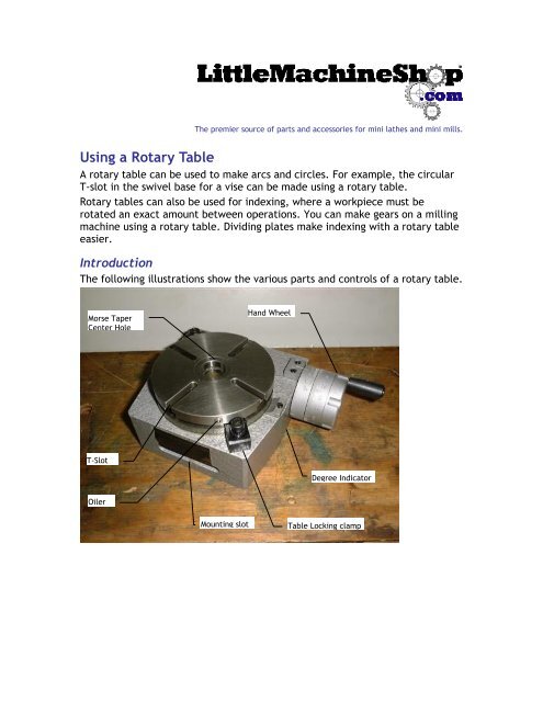
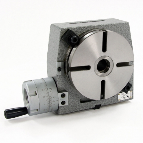
A rotary table used in conjunction with a mill allows a machinist to produce virtually any part they can design. Sherline’s rotary table is a precision piece of equipment that has been designed to work with their vertical milling machines. However, it can be used on any mill whenever the small 4-inch size would be an advantage. The only limits are size, not complexity.
The table is 2″ high and 4″ (100mm) in diameter. The main components have been machined from solid bar stock steel, and the complete unit weighs seven pounds. The table has been engraved with a laser, giving sharp and precise lines every 5°, numbered every 15°. These lines are calibrated with the 72-tooth worm gear that is driven by the handwheel. The handwheel is divided into 50 parts, making each line on the handwheel 1/10°. This allows a circle to be divided into 3600 increments without interpolation. Seventy-two revolutions of the handwheel rotate the table one revolution.
The rotary tables can hold more weight when they are not under a continuous load. Click on the Video tab above to see examples of different weights and uses for our rotary tables.
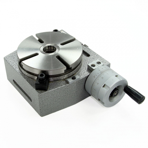
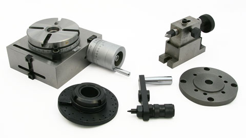
The table T-slots are identical to those used on the Sherline mill and lathe, making the vast line of Sherline tooling available for use with this product. Two hold-down clamps and T-nuts are provided with the table. Also included is an adapter that allows Sherline’s 3- and 4-jaw chucks to be screwed directly to the rotary table. An optional right-angle attachment is available (P/N 3701) to mount the table in the vertical position to increase its versatility further. With the table mounted vertically, an optional adjustable right-angle tailstock (P/N 3702) can be mounted to the mill table. It is used to support and stabilize the other end of long work held in a chuck or otherwise attached to the rotary table.

Not sure I agree with you folks that claim that one needs a rotab in order to make a rotab. However, depending on the size of table you want to make you will need a lathe with a swing at least as large as the rotab. IOW your rotab will be a teensy one.
Home Shop Machinist magazine is full of such projects. Look in the Periodicals/Crafts section of your local Barnes & Noble or Borders book store. You may have to dig a bit to find it behind all the wood working mags.
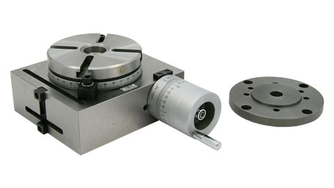
The mill rotary table is one of the main accessories of milling machine. As a precision work positioning device, it is widely used for indexing drilling, milling, circumferential cutting, boring, etc. The rotary turn table for milling machine is made from casting with high quality, can work with a set of dividing plate.
Both vertical and horizontal with two functions. Circle cutting, indexing drilling, milling and more complicated work are possible when the vertical position of the table is used together with the tail part.
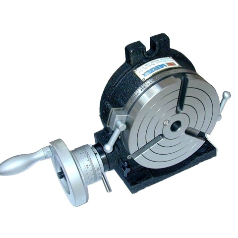
A rotary table is a precision work positioning device used in metalworking. It enables the operator to drill or cut work at exact intervals around a fixed (usually horizontal or vertical) axis. Some rotary tables allow the use of index plates for indexing operations, and some can also be fitted with dividing plates that enable regular work positioning at divisions for which indexing plates are not available. A rotary fixture used in this fashion is more appropriately called a dividing head (indexing head).
The table shown is a manually operated type. Powered tables under the control of CNC machines are now available, and provide a fourth axis to CNC milling machines. Rotary tables are made with a solid base, which has provision for clamping onto another table or fixture. The actual table is a precision-machined disc to which the work piece is clamped (T slots are generally provided for this purpose). This disc can rotate freely, for indexing, or under the control of a worm (handwheel), with the worm wheel portion being made part of the actual table. High precision tables are driven by backlash compensating duplex worms.
The ratio between worm and table is generally 40:1, 72:1 or 90:1 but may be any ratio that can be easily divided exactly into 360°. This is for ease of use when indexing plates are available. A graduated dial and, often, a vernier scale enable the operator to position the table, and thus the work affixed to it with great accuracy.
Rotary tables are most commonly mounted "flat", with the table rotating around a vertical axis, in the same plane as the cutter of a vertical milling machine. An alternate setup is to mount the rotary table on its end (or mount it "flat" on a 90° angle plate), so that it rotates about a horizontal axis. In this configuration a tailstock can also be used, thus holding the workpiece "between centers."
With the table mounted on a secondary table, the workpiece is accurately centered on the rotary table"s axis, which in turn is centered on the cutting tool"s axis. All three axes are thus coaxial. From this point, the secondary table can be offset in either the X or Y direction to set the cutter the desired distance from the workpiece"s center. This allows concentric machining operations on the workpiece. Placing the workpiece eccentrically a set distance from the center permits more complex curves to be cut. As with other setups on a vertical mill, the milling operation can be either drilling a series of concentric, and possibly equidistant holes, or face or end milling either circular or semicircular shapes and contours.
To create large-diameter holes, via milling in a circular toolpath, on small milling machines that don"t have the power to drive large twist drills (>0.500"/>13 mm)
with the addition of a compound table on top of the rotary table, the user can move the center of rotation to anywhere on the part being cut. This enables an arc to be cut at any place on the part.
Additionally, if converted to stepper motor operation, with a CNC milling machine and a tailstock, a rotary table allows many parts to be made on a mill that otherwise would require a lathe.
Rotary tables have many applications, including being used in the manufacture and inspection process of important elements in aerospace, automation and scientific industries. The use of rotary tables stretches as far as the film and animation industry, being used to obtain accuracy and precision in filming and photography.
Can any of you recommend a good online source of information on buying, setting up and using a Rotary Table. I don’t yet have one but I have a few projects in mind that will require one. TIA.
A Rotary Table that can be set on the milling machine table in either horizontal or vertical mode can be used in lieu of a Dividing Head (Especially if Division plates are available )
In my case this involves using adaptor sleeves in the lathe, which are then removed to mount the chuck, complete with workpiece, into the Rotary Table on the mill to cut the teeth. (Again, in my case, a small Myford fitting chuck is mounted on a 2MT arbor. In the lathe a drawbar holds it in place, and in the R T, an Allen capscrew and top hat bush pull it into the taper.
I fitted the Tailstock with two dowels to locate in the T slots of the mill table. They may need to be stepped. . I bored a 2MT stub arbor to a very close fit on the Tailstock arbor. In this way the Tailstock can be adjusted to exactly the centre height of the Rotary table, and the Tailstock, being located on the mill table, aligns the Rotary table along and across the mill table.
Hi Vic I bought a rotary table and three jaw chuck of the same diamiter to mount on top. The one thing I forgot to take into account was the chuck had three equally spaced mounting holes and the rotary table had four equal T slots so I had to make a mounting adaptor plate to go between the two. It wasn"t a problem but just another job and it slightly reduces the usable height under the spindle.
Vic - As a regular user of R/T"s the only thing I would add is look to a vertical and horizontal mountable version if possible and definitely choose a four slot table as opposed to a three. The four slot are much easier to set up on if the table area is small.
Here"s an example (though smaller in diameter than the table) on the MES but the same principle. BTW a set of small clamps using cap heads for bolts are invaluable on RT set ups where space is at a premium
It’s a bit of a minefield out there. Some RT tables say in the description the gear ration is 90:1 or 36:1 but some don’t mention it at all. Is there a clue of what the ratio might be by looking at the division markings on the hand wheel collar?
Vic, i hope you started by reading the dozens of threads on this forum for both rotary tables and dividing heads as the replies tend to intermingle subjects. Now I notice you are a major participant on here so I am probably preaching to the converted of course.
If you plan to do small jobs a grid of tapped holes adapter plate makes setting up vastly easier. The common import strap and stepped packing blocks are cumbersome at the ebst of times and, frankly, way too big for the samller breed of table.
Alloy tooling plate is probably the best material. On a 100 mm table M5 holes on a repeating 20 mm square with one in the middle 5 spot dice pattern would probably work well. My tables are bigger so I bought aluminium breadboards from Thor Labs, an optical laboratory equipment supplier, having M6 holes on a 25 mm 5 spot pattern which work well. Not cheap cheap but sufficiently inexpensive to outweigh the tedium of drilling and tapping lots of holes. If you make one best to machine tap with a good spiral point tap.
Tug shows some nice, compact clamps. My version is a little posher with a knurled thumb screw to set the height at the back having a free running pad at the bottom to protect the table or hole plate. More work for more swank but no realistic gain in function.
Vic, i hope you started by reading the dozens of threads on this forum for both rotary tables and dividing heads as the replies tend to intermingle subjects. Now I notice you are a major participant on here so I am probably preaching to the converted of course.
Buy the largest r/table that you can afford/lift/ and will fit your mill, small ,r/tables are ok when fitted with chucks but when it comes to clamping work direct to the table a lot of space is required for clamps,though extra space can be achieved by fitting a subplate to the table,secured by countersunk screws fitting into the t nuts,and then drilling and tapping the subplate with a suitable pattern of tapped holes. when I could no longer lift a very heavy French Dufor 12 inch table I swapped it for an industrial Taylor Hobson 10 inch table , I now use it on my Elliott 00 omnimill and though its a little large for the mill it will take most jobs and clamps,my small far eastern 6 inch r/table has not been used for many years ,generally too small ,
Re rotary tables, I have an HV6 clone from Warco. Many variants around, the word on the street being Vertex are better made than most. Mine"s OK. It has a 90:1 worm, does horizontal and vertical, and came with a dividing set of hole wheels and fingers. They"re important because most of us lack the memory, concentration and intellectual horse power needed to twirl a rotary table handle correctly for anything other than straightforward integer degree work. Hex head cutting is easy, but the operator needs mechanical help to do most gears. (An even better answer is a computer driven stepper motor.)
One reservation. The table is on the delicate side, fine for turning an angle, locking, and taking a cut. Using it to feed metal into a cutter, as when spoking a wheel, is likely to cause severe wear if done frequently and over-enthusiastically. If needed for that type of work, might be better to look for an industrial table. But beware, they"re expensive and although they take more abuse, they can be wrecked in this mode too. Nothing like busting a Bison to ruin your day!
Thanks for the tip Dave, yes that search is so much better! Sorry, another question. Folks have said four slots are better but how do you fit a scroll chuck with three studs to a table with four slots? I’ve seen a simple way of mounting on a three slot table without any adapters etc, just using studs and round nuts with holes for a Tommy bar.
I have two 3 Jaw chucks mounted on backplates that are a bit larger than the chuck body which allows the backplate to be held to the table with tee nuts, a spigot on the backplate to locate in the table"s central hole make sfor easier set up.
Yep - Jason beat me to it but my set up is the same - chuck to plate, plate to table. Plate has locating spigot to fit table bore, chuck has locating spigot to fit a recess in the plate and the chuck bore.
Ditto with the four versus three slots - four allows more versatile clamping of parts when using table alone. Buying a three slot just so the chuck can be mounted is limiting the versatility for something that is not used that often - well not on the R/T in the fashion shown. Both Jason and I have R/T"s larger than the chuck body but you can still have a plate interposed even if the diameters are the same.
Those large tee slots however were cast in originally - anything but smooth so took a fair bit to clean up. I later added the degree ring and the stops - if there is one thing to improve an R/T it is to fit some kind of adjustable stop set up as they take all the worry of, and potential for, over movement to occur, something that"s easily done on a R/T
I have H/V rotary table and followed an article in MEW, making a stepper motor controller using an Arduino, not easy for me, got there with a lot of help from folks on "here" thank you chaps. How good it is when cutting a gear, NO losing count, or thin tooth, so after the purchase, I suggest you consider making a controller. John
Obviously, being a screw fit chuck, if using for radius cutting, the direction of table rotation / cutting forces need to taken into account, to prevent the chuck coming loose...
So far, with Tailstock support, have had no problems with unwanted movement when cutting gears (Table face vertical, axis horizontal ) Since gear cutting involves a full depth cut with SLOW feed , this seems to have worked, so far!


 8613371530291