
precision rotary table free sample
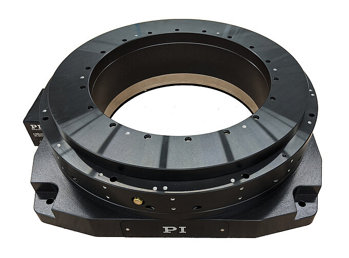
PI’s direct-drive rotary tables with frictionless, brushless, closed-loop torque motors provide the best combination of high accuracy, high velocity, and maximum service life. PI provides closed-loop direct drive rotary tables with both mechanical bearings and air bearings. Stage models with large apertures and low profile are available. The stage design is optimized for high speed, stiffness, and high load capacity. If completely friction-free and maintenance free motion with virtually unlimited lifetime is required, air bearing rotation tables are recommended. These ultra-precision, high-speed rotary tables provide vibration-free motion with extremely high accuracy and negligible runout, wobble and eccentricity errors. The lack of lubricants makes these also clean room compatible and ideal for any high-performance metrology application in optics, photonics, and semiconductor manufacturing, test and metrology related projects.
In contrast to worm gear driven rotary stages or belt-drive rotation stages, torque-motor direct drive stages eliminate play in gears, couplings or flex in drive belts, providing motion with zero backlash and excellent constancy of velocity, while achieving higher speed than worm-gear drives.
PI’s precision direct-drive, positioning tables can be used in high performance factory automation, research, semiconductor, and laser processing applications. Due to the use of brushless high-torque, motors with direct metrology position feedback, backlash is completely eliminated, and reliability is greatly improved.
With modern direct-metrology rotary encoders, sensor resolution down to 1/100th of a microrad is available on select models with large rotary table platforms, using the high interpolation factors
Based on the high encoder resolution and powerful servo controllers, the direct-drive rotary tables also provide excellent velocity control, which is required in automation applications including high-speed laser processing, indexing, and semiconductor wafer inspection.
Most Direct Drive Rotation stages can be mounted horizontally and vertically, and with combinations all 3 rotary degrees of freedom (3DOF, pitch, yaw, and roll) can be addressed.
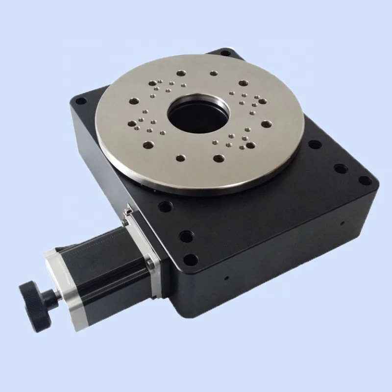
Our direct drive rotary tables provide high torque and are easy to integrate. They contain high-energy magnets in a simplified mechanical design and drive loads directly without the need for a transmission mechanism or gearbox. It allows customers to build them right into a drive system for flexible placement and integration with cooling pipes and cables, for example.
We supply a wide range of frameless motors, and our adjustable motors include an optical encoder, scale, bearing and housing. Given our selection, it can be challenging to choose the best direct drive motor for your project. Our engineers prefer to help you find the right rotary table for your requirements.
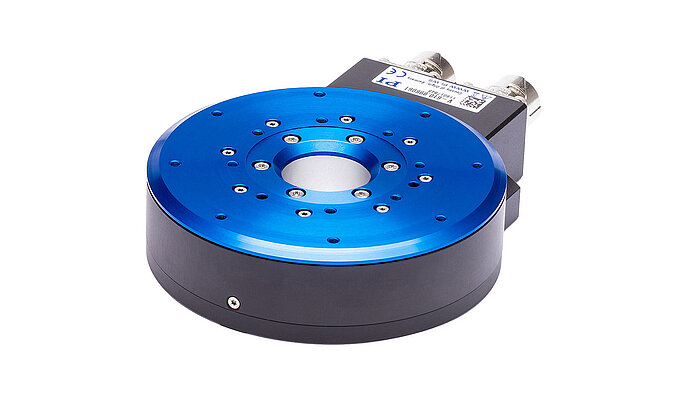
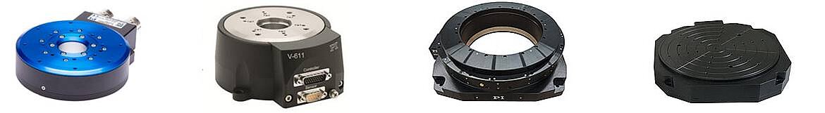
Our most popular rotary motor, the AXD series is characterized by a slim, compact "pancake" design with high peak and continuous torque despite the motor"s quite small form factor.Direct drive and brushless motor
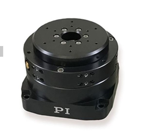
The ACD series is a set of ironless rotary tables. This motor is cogging-free and features high-resolution optical encoder feedback and low speed variability. This permanent magnet motor is equally suited for either low or high speed applications.Zero cogging coreless motor
The ACW series features a cogless construction and lean design, with high-precision coding and ultra-precision bearings. Together, this results in our highest performing motor in terms of repeatability and smooth motion.Direct drive brushless motor
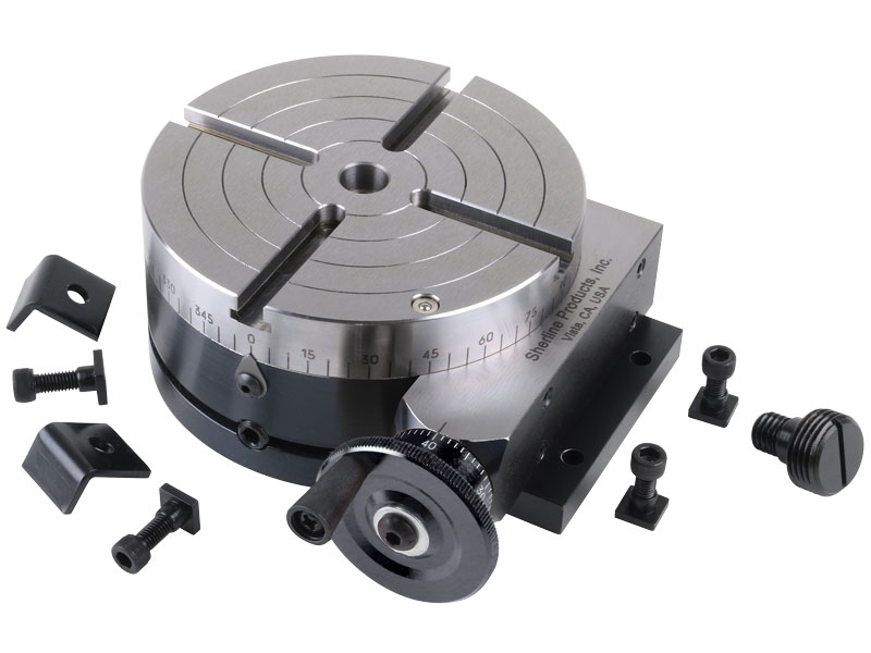
The H2677 manual was written by our U.S. based Technical Documentation Department and is packed with useful information. The complete and easy-to-read manual makes it easier to assemble and maintain your rotary table.
The Grizzly Customer Service and Technical Support Teams are U.S. based. Parts for the rotary table may be available online and shipped from the Grizzly parts warehouse in Springfield, MO.

Linear Motors can be used in cleanroom environments. In fact, many front-end semiconductor applications have linear motors in use. In wafer manufacturing plants, high-precision lithography machines, for example, use linear motors in XY positioning tables with very high accuracy (nanometer resolution) and submicron accuracy in cleanroom classes according to ISO 2.
The assembly tables with reciprocating movement rotate on the horizontal plane. They are used to equip semi-automatic or automatic loading stations. Incorporated fine pitch stop screws made of hardened ...
... SA conceived these electric rotating tables for an integration in automatic rotating machines, for transport and assembly where precision and dynamism are asked.
... X-RSW-E Series products are motorized rotary stages with built-in controllers. Rated for 2.25 N-m of torque, speed up to 75 rpm, and a load capacity of up to 20 kg, these stages are ...
RTGA Series motorized rotation stages provide precision angular positioning accuracy combined with high load capacity. There are three stage sizes with center aperture ...
Velmex Rotating Tables deliver precise, continuous rotating motion for scanning, assembly, testing and production. They are a convenient, accurate method of quickly positioning or rotating ...
For the past fifty years, TRT has been the most frequently used rotary table. TRTs are electric, driven by fully CNC Brushless motor with precision reducer. Position and rigidity are ...
Jenaer Antriebstechnik GmbH"s HRT-100 Series of hollow-shaft rotational tables feature n x 360° rates, mechanical and electrical connection readiness, and integrated ES Series motors. They feature hole ...
The Rotating rotary table DSH-S Series is manufactured by Isel Germany. The product has a compact and durable design; it is made of stainless steel that has protection class of IP 65. ...
The RT series of our precision rotation stages is used where rotation-symmetric components and assemblies are measured with highest accuracy or for positioning. The free from float pre-stressed ball bearings ...
... Drive Rotary Table is a kind of rotary table used to the continuous operation which is several times more agile and accurate than conventional face gear or rack and pinion ...
... acoustics Remote-operated Turntable HRT I is used for automated orientation-dependent acoustic measurements, allowing to rotate the device under test to specific angles in the measurement field.
This is the Hollow Rotary Table model number GSN60-05K-SV with table size 60mm gear ratio 1:5 for servo motor. GIGAGER Hollow Rotary Table also called ...

Kaka Industrial HV-8, 8”Horizontal Vertical Rotary Table Rotary table TSL Vertical & Horizontal MT3 Center Sleeve Rotary Table 4 slot Precision Milling Table 360 Degrees Precision Rotary Table
Kaka Industrial HV-8, 8”Horizontal Vertical Rotary Table Rotary table TSL Vertical & Horizontal MT3 Center Sleeve Rotary Table 4 slot Precision Milling Table 360 Degrees Precision Rotary Table

PRECISION ROTARY TABLE Filed July 14, 1969 2 Sheets-Sheet 2 INVENTOR 17/?771? ED515727 ATTORNEY United States Patent 3,615,068 PRECISION RUTARY TABLE Arthur Edelstein, Jamaica, N.Y., assignor to Ardel Instrument Co., Inc., Jamaica, N.Y. Filed July 14, 1969, Ser. No. 841,417 Int. Cl. A47b 95/00, 91/00 US. Cl. 248-349 17 Claims ABSTRACT OF THE DISCLOSURE A precision rotary table for use in electro-optical research includes a stationary base member and a movable support part operatively connected to the base member and rotatable relative thereto. Precise positioning of the movable part in response to actuation of a manually operated means is effected by employing gearing mechanism in which the various rotating parts are continuously subjected to a constant force in a direction such that the meshing gears are placed in back-lash-free engagement with each other. An attachment device may be rotatably connected to the movable part, that device including mechanism which permits quick movement of the attachment device between two preselected positions.
A wide variety of rotary tables are currently used for research purposes. These tables are employed to rotate prisms, crystals, pol-arizers and the like to desired rotative positions. It is imperative in most applications that such positioning be carried out with great precision. Furthermore, it is extremely important that the rotary table be capable of repeatedly positioning the device with the same precision. Unfortunately, manufacturing tolerances which occur in the normal manufacture of the several movable parts in a rotary table render it virtually impossible to achieve a positioning :accuracy of better than a certain lower limit. Thus, far, increased accuracy in rotary tables of this type have been attempted by careful manufacture of the various parts, but even parts made by special techniques still include variations in dimensions which adversely affect the preciseness with which the device can be operated.
The subject invention provides a solution to the aforementioned difficulties by the inclusion of a means so positioned and structured that the various rotating parts in a rotary table are held under constant pressure in close contact with each other. In this manner, lost motion between the rotating parts is prevented and the accuracy of the rotary table is greatly increased.
Broadly, the rotary table of the invention comprises a stationary base member, a ring-like support part operatively connected to the base member and rotatable relative thereto, first means operatively connected to the support part for rotating the part, and means effective to continuously force the first means into a tight engagement with the support part during the operation of the device so that lost motion between these rotating members is prevented.
In one embodiment of the invention, the first means includes a pinion which is mounted on a shaft carried in bearings. The pinion meshes with a gear which is integrally secured to the support part and drives the part through the gear engagement. In the preferred embodiment a driving means for rotating the first means is included and comprises a worm afiixed to a second shaft and a worm wheel secured to the pinion shaft in a position to mesh with the worm. A manually rotatable means such as a knurled knob is secured at one end of the second 3,615,068 Patented Oct. 26, 1971 "ice shaft so that motion of the rotating components may be manually effected.
If properly located, the resilient member may provide still another force component along the axis of the pinion shaft. In the preferred embodiment this is accomplished by wedging the resilient member between a shoulder on the bearing and a flange on the base member, both the shoulder and flange being extended substantially laterally relative to the "aXis of the shaft and being spaced from one another substantially axially of the shaft. With this construction, the worm wheel and the pinion are axially positioned relative to their respective mating gears due to the resilient member being compressed axially in the space. In order to ensure the permanency of the gear location during the operation of the rotary table, the lower portion of the pinion shaft engages a non-resilient device such as a washer or the like, which rests on the base member. Still another resilient member may be placed below the lower bearing in order to provide a further radial force to the shaft so that additional radial pressure on the pinion and worm wheel may be provided.
Because a high degree of accuracy is desired, the manually rotatable means in the preferred embodiment is turned only one revolution for every arc degree traversed by the circular part. With this arrangement, the position of the circular part may be monitored at intervals of one are minute. However, it will be appreciated that with such a fine accuracy the manually operated means must be rotated many times for the circular part to traverse any considerable distance. Thus, if it is desired to rotate the table 90 turns will be required. Many times during the use of a rotary table such as in polarizer experiments, a particular angle must be repeatedly traversed. A rotary attachment device is therefore provided to enable the operator of the rotary table to repeatedly traverse a large distance in a short period of time. The attachment device is preferably mounted on the previously described rotatable part. It includes a lower element which is secured to the rotatable part and an upper element rotatably mounted on the lower element. The upper element functions as a rotary table itself once the attachment device is mounted in position, that is, it carries an optical device to a position along the arc of the circle over which the upper element is moved. Positive stops may be provided on the stationary base member and on the lower element of the attachment device between which the upper element of the attachment device is freely movable, thus providing for rapid but accurate positioning of that upper element in either of two predetermined positions. The rotative spacing between those positions can be accurately adjusted and varied by rotating the rotatable part of the device proper, which carries the lower element of the attachment device.
To the accomplishment of the above, and to such other objects as may hereinafter appear, the present invention relates to the construction of a rotary table device as defined in the appended claims, and as described in this specification, taken together with the accompanying drawings, in which:
Referring to FIG. 1, a rotary table is designated generally by the numeral or frame 10. The table 10 includes a base member -12 and a cover 14 secured to the base member by means of bolts 16. A ring-like support part 18 (on which the optical device or the like is adapted to be mounted) is rotatably positioned in one area of the cover 14, and includes a series of markings 20 which indicate in degrees the circumferential position of the support part 18. For this purpose an index pin -22 is mounted in the cover 14 and positioned adjacent the markings 20 .on the part 1-8. The cover "14 is also provided with a plurality of holes 24, continuing into base member 12, which may be used for mounting the table to a support. Holes 27 in the part 18 may be used for mounting other devices to hold prisms, crystals and other optical components. A large opening 25 is also provided in the central portion of part .18 so that the optical component may be rotated on its axis, that is, sothat light may enter from below the optical component. A manually rotatable member generally designated 26 includes a knurled knob section 28 and a section 30" which is provided with a plurality of index marks. The section 30 is positioned adjacent a bushing 32 fixed in base member 12 which is also provided with index marks. As illustrated more clearly in FIG. 2, the member 26 is spaced from the bushing 32 as shown at 34 and is rotatable relative thereto. In the actual operation of the device, the part 18 is driven in rotation by the rotation of the member 26. An indication of the specific amount of movement is obtained by reading the position of part 18 at the markings 20 and the position of the markings on section 30, the latter constituting a Vernier or fine indication and the former constituting a coarse indication.
The coupling mechanism between the manually rotatable member 26 and the part 18 is more clearly illustrated in FIG. 2. As there shown, the member 26 is tightly connected to a shaft 36 by means of a screw 38. The connection between member 26 and the shaft 36 is a rigid one since it is highly desirable that there be no motion between these parts when the member 26 is rotated. Worm 40 is pinned to shaft 36, and is constrained axially of the shaft 36 by spring washer 41. Worm 40 in turn meshes with worm wheel 42. The worm wheel 42 is mounted on a shaft 44 (see FIG. 4). The pinion gear 46 is also securely mounted on shaft 44 directly above the worm wheel 42. The ring-like part 18 is integrally formed with a gear 48, which meshes with and is driven by the pinion 46.
It has been determined that a preferred gear reduction ratio between the part 18 and the manually rotatable member is in the order of 360:1. In one embodiment, the gear ratio between gear 48 and the pinion 46 may be 12:1, while the ratio between the worm wheel 42 and the worm 40 is approximately 30:1. With this high ratio, one turn of the member 26 will move the circular part 18 only one arc degree. The index marks on the section 30 of the member 26 can therefore be graduated to increments of as low as one are minute, which is lower than most precise devices currently in use.
FIGS. 6 through 8 illustrate a rotary attachment device 86 which may be mounted on the rotary table device 10 shown in FIG. 1. Referring to FIG. 6, it will be seen that the attachment device is generally designated by the numeral 86 and comprises a lower part 88 which is secured to the inside surface of the gear 48 by means of a set screw 90. An upper part 92 is operatively connected to lower part 88, and is rotatable relative thereto. In order to effect the rotation a plurality of bearing balls 94 are interposed between the parts 88 and 92, the balls sliding in the V groove 96 in part 88 and are secured in position by set screws 98 in part 92. A projecting tab 100 is secured to the upper rotary part 92 by screw 102. A similar projecting tab 104 is secured to the stationary part 88 by means of screw 106. This tab 104 is provided with an extending button 108 which projects upwardly a distance such that it extends into the path of movement of projecting tab 100.
FIGS. 7 and 8 illustrate by means of plan views the relative positions of the several tabs 100 and 104 during the operation of the device. As shown in FIG. 7 a stop member 110 is pressed into the cover 14 on the rotary device 10 and extends upwardly therefrom. The tab 100 is initially positioned in contact with stop member 110 and the tab 104 is positioned initially such that the extended button 108 engages the edge 112 of the tab 100. This alignment of members represents the starting position for the device. Since tab 104 is fastened to the stationary part 88, and the stationary part 88 is fastened to the gear 48 on the rotary device 10, the manually operated member 26 controls the position of the stationary part 88. Therefore, when the member 26 is rotated part 88 is carried with part 18 to a desired position. The tab 104 is carried with part 88 while the part 92 and its tab 100 are also rotated to the new position. The new position is illustrated in FIG. 8, and by way of example represents a 90 movement of the parts 18 and 88. This position is marked by the extended button 108. As noted, the tab 100 and the upper part 92, to which it is affixed, are rotatable relative to the lower part 88 and the tab 104 which is connected to it, and are shown after rotation back to stop 110. Thus, if the optical device which is to be positioned is joined to the attachment device 86 after the desired position represented by the position of button 108 is achieved, then the optical device can be accurately and quickly rotated 90 by rotating tab 100 and part 92 between the button 108 and stop member 110, those elements representing two accurately positioned stops between which an optical device may be quickly and repeatedly maneuvered with no sacrifice in accuracy.
From the foregoing it will be appreciated that a rotary device of the invention is capable of precise positioning of an optical device or the like about an arc of 360. The prevention of lost motion between rotary parts enables the rotation to be effected with an accuracy heretofore not readily achieved. In addition, an attachment device enables any position to be accurately repeated without the necessity of tedious manipulation of the various parts.
1. A rotary device effective for precisely locating a rotative position comprising a frame, a support part operatively connected to said frame and rotatable relative thereto, first means operatively connected to said support part and said frame for rotating said part, said first means comprising at least two rotatable means operatively connected in driving relationship, and forcing means effective to apply a pressure on at least one of said rotatable means in a direction perpendicular to its axis of rotation to forcefully maintain driving engagement between said rotatable means during the operation of said rotary device, such that there is substantially no lost motion between said rotatable means during the operation of said rotary device even after considerable wear of the meshing gear surfaces.
2. The device of claim 1, in which said rotatable means comprises first and second gearing means operatively connected to said support part and said frame respectively, said forcing means being effective to positively maintain said first and second gearing means forcefully meshed in operative driving engagement.
3. The device of claim. 2, wherein said first gearing means is fast on said support part and said second gearing means is fast on a shaft, means rotatably mounting said shaft on said frame, said forcing means comprising means disposed between said shaft and said frame and effective to apply a positive radial pressure on said rotatable mounting means in a direction to forcefully mesh said second gearing means with said first gearing means.
5. In the device of claim 3, driving means for rotating said second gearing means, said driving means comprising third and fourth gearing means operatively meshed together, said third gearing means being fast to said shaft and said fourth gearing means being operatively drivingly connected to a manually rotatable member, whereupon when said manually rotatable member is rotated the rotative motion thereof is transmitted to said support part to rotate the same, said forcing means being effective to simultaneously apply a pressure to said first and third gearing means in a direction to forcefully maintain them in operative meshing engagement with said second and fourth gearing means, respectively, during the operation of said rotary device, whereby lost motion between said first and second gears is substantially prevented.
11. In combination with the device of claim 1, a rotary attachment means comprising a lower part secured to said support part, an upper part operatively connected to said lower part and rotatable relative thereto, and a tab extending outwardly from said upper part on said attachment device, said tab on said upper part being movable to a specific position by the movement of said upper part relative to said lower part, and a stop element carried by said lower part toward which said upper part tab is movable and with which said upper part tab is engageable.
17. In a gear train for a precision rotary device having 7 a frame, a member rotatably mounted in said frame, and an adjusting means for adjusting the rotary position of said rotatable member on said frame, a first gearing means in operative driving relationship to said rotatable member, a shaft rotatably mounted in said frame in operative driving relationship to said adjusting means, a second gearing means mounted fast on said shaft, a resilient bearing member disposed between said shaft and said frame, said resilient member being compressed against said frame as a result of the operativemeshing engagement of said first and second gearing means, thereby forcefully to maintain said operative meshing engagement even after considerable wear of the meshing gear surfaces.
In 1996, Precision Detroit Company established a relationship with WEISS GmbH. WEISS has been manufacturing high quality index tables for decades and is the leading automation component manufacturer in Europe today.
In August, 2007, WEISS GmbH established WEISS North America, Inc. as a wholly-owned subsidiary. On September 30, 2007, WEISS North America, Inc. acquired the assets of Precision Detroit Company, Inc. relative to its PDC Geneva Motion index tables and its network of sales representatives throughout the U.S. and Canada.
Today, WEISS North America is not only a rotary table manufacturer but your complete automation manufacturer and solutions partner. WEISS has decades of expertise in providing automation, drive and control solutions to industrial markets. WEISS offers industry-specific, cost-effective and efficient technology solutions to help you maximize your efficiency, increase your productivity and achieve optimal system performance. We understand that your application has unique processes and specific requirements and we work closely with you to develop the perfect automation solution for your particular needs.
The hydrostatic rotary tables from ZOLLERN impress with their durability and a high concentricity and axial runout accuracy. Thanks to the ZOLLERN bearing clearance compensator, the optimal pocket pressure is set automatically and independently of production tolerances. The freedom from friction at low speeds prevents slip stick and therefore allows maximum positioning accuracy.
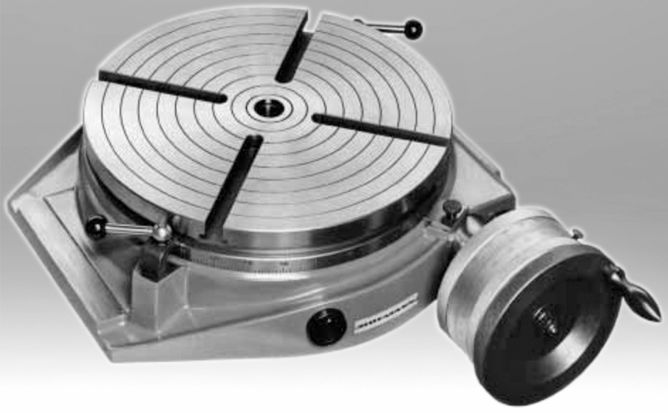
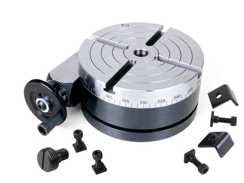
The mill rotary table is one of the main accessories of milling machine. As a precision work positioning device, it is widely used for indexing drilling, milling, circumferential cutting, boring, etc. The rotary turn table for milling machine is made from HT200 casting with high quality. It has already passed the ISO9001 quality system certification. They are are very popular on the market for their superior performance, excellent design and reasonable cost.
Both vertical and horizontal with two functions. Circle cutting, indexing drilling, milling and more complicated work are possible when the vertical position of the table is used together with the tail part.


 8613371530291